MeetMe Plus 用户手册(参与人)PDF
- 格式:pdf
- 大小:2.40 MB
- 文档页数:57

目录1. 快速应用指南 (8)2. 一般信息 (9)2.1. 应用围 (9)2.2. 适应征 (9)2.3. 禁忌症 (10)2.4. 警告 (10)2.5. 注意 (12)3. 介绍 (15)4. 间断的容积和热稀释测量 (19)4.1. 心输出量的测量原理 (19)4.2. 容积的测量原理 (19)4.3. 通过经肺热稀释法获得的参数 (22)4.3.1. 经肺心输出量(CO) (23)4.3.2. 胸腔血容积(ITBV) (23)全心舒末期容积(GEDV) (23)4.3.3. 血管外肺水(EVLW) (29)4.3.4. 肺血管通透性指数(PVPI) (33)4.3.6. 全心射血分数(GEF) (35)5. 脉搏轮廓分析 (36)5.1. 测量原理 (36)5.2. 脉搏轮廓分析的校正 (40)5.3. 通过脉搏轮廓分析获得的参数 (40)5.3.1. 脉搏轮廓心输出量(PCCO) (41)5.3.2. 动脉压(AP) (41)5.3.3. 每搏输出量变异(SVV) (42)5.3.4. 脉压变异(PPV) (42)5.3.5. 全身血管阻力(SVR) (43)5.3.6. 左心室收缩力指数(dP/dtmax) (44)6. 正常值围 (46)7. 文献 (48)8. 系统描述 (60)8.1. 一般信息 (64)8.1.1. 应用围 (64)8.1.2. 适应征 (64)8.1.4. 警告 (64)8.1.5. 注意 (67)8.2. 拆箱和检查 (70)8.2.1. 拆箱 (70)8.2.2. 检查 (70)8.3. 启动机器 (71)8.3.1. 要点 (71)8.3.2. 细节 (73)8.4. 菜单描述 (77)8.4.1. 输入菜单 (80)8.4.2. 压力调零菜单 (82)8.4.3. 设置菜单 (82)8.4.4. 主菜单 (84)8.4.5. 热稀释测量显示页 (86)8.4.6. 脉搏轮廓测量显示页 (92)8.4.7. 信息屏幕 (95)8.4.8. 热稀释信息屏幕 (97)8.5. 打印机 (98)8.6. 调整对比度 (99)8.7. 信号输入指示/警告指示 (100)8.8. 待机模式 (100)8.9. 电池功能 (101)8.10. 问题处理 (102)8.10.1. 出错信息 (102)8.10.2. 信号传输 (106)8.11. 设备的清洁和灭菌 (109)8.12. 维护/服务 (110)8.13. 将动脉压信号传输到床旁监护仪 (112)8.14. 使用RS232接口传输数据 (116)8.14.1. 一般情况 (116)8.14.2. 数据传输 (118)9. 消耗品 (119)9.1. PULSIOCATH PCCO导管套件 (119)9.2. PCCO压力测量套装 (121)9.3. 注射液温度探头固定仓 (121)9.4. PiCCO导管大包装 (121)9.5. 一次性使用的配件 (122)10. 配件 (123)11. 技术参数 (125)12. 附件 (127)A 计算公式 (127)B 国际符号 (134)C 服务保证 (135)D 名词解释 (137)E 认证证书 (142)图示图1:某种指示剂的稀释曲线图示及感兴趣的特定时间 (20)图2:指示剂在心肺系统的混合腔室图示 (21)图3:重症监护病人全心舒末期容积(GEDV)和胸腔血容积(ITBV)的回归分析 (24)图4:每搏输出量指数(SVI)和全心舒末期容积指数(GEDVI)的回归分析 (26)图5:猪的每搏输出量指数(SVI)和中心静脉压(CVP)回归分析 (27)图6:猪的每搏输出量指数(SVI)和肺毛细血管楔压(PCWP)回归分析 (28)图7:综合使用EVLW和ITBV治疗病人 (32)图8:全心舒末期容积指数(GEDVI)和心指数(CI)关系示意图 (35)图9:心脏周期的顺应性情况 (37)图10:个体主动脉顺应性的测量 (38)图11:脉搏轮廓心输出量(PCCO)的计算 (39)图12:PiCCO plus的前面板 (60)图13:PiCCO plus的后面板 (62)图14:PiCCO plus的连接 (71)图15:PiCCO plus软件操作流程图 (79)图16:打印机 (98)图17:压力信号传输到床旁监护仪时后面板的连接 (112)前言在使用PiCCO plus机器之前,请仔细阅读这本操作手册!警告为避免损伤病人和其他人员,操作者应了解本手册中的警告信息。
A V AYA CM 之引导和引导号码-与我会面电话会议用户利用与我会面电话会议功能,可以通过呼叫会议号码的方式建立多达6 方的电话会议。
与我会面电话会议使用呼叫引导来处理此会议电话呼叫的设置。
与我会面电话会议可以要求接入码。
如果已指定接入码,并且该引导已被编程为期待接入码,那么每位用户在与我会面会议电话呼叫时必须拨打正确的接入码方能被加入呼叫。
任何用户可拨叫与我会面电话会议的分机号,前提是该分机号码属于该用户的DID 号码组。
设置与我会面电话会议需要三个基本步骤:1 确定用户选项已设置为接受与我会面电话会议。
2 创建与我会面电话会议VDN。
3 为与我会面电话会议创建一个引导。
确认用户选项让我们首先确认用户选项已得到正确设置。
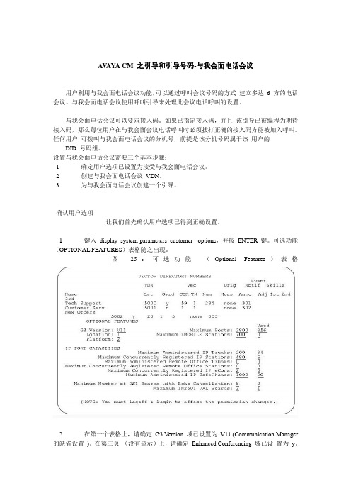
1 键入display system-parameters customer- options,并按ENTER 键。
可选功能(OPTIONAL FEATURES)表格随之出现。
图25:可选功能(Optional Features)表格2 在第一个表格上,请确定G3 Version 域已设置为V11 (Communication Manager 的缺省设置)。
在第三页(没有显示)上,请确定Enhanced Conferencing 域已设置为y。
设置与我会面电话会议VDN现在让我们来设置与我会面电话会议VDN。
就本例而言,我们将此会议设置在36090 分机:1 键入add vdn 36090,并按ENTER 键。
36090 分机的增加VDN (Add VDN)表格就会出现。
让我们为此VDN 指定引导90。
图26:引导电话簿号码(Vector Directory Number)表格(第一个增加表格)注意:如果此VDN 分机号属于该用户的DID 号码组,外部用户将能够接入此电话会议VDN。
如果此VDN 分机号不属于该用户的DID 号码组,那么只有此用户网络(包括DCS 或QSIG)上的内部用户或远程接入呼叫方才能够接入此电话会议VDN。

连通宝用户手册(计算机用户——5.1版)目录1前言 (4)大纲 4专业术语 (4)2限制 (6)3安装连通宝 (7)3.1手动下载 (7)3.2 自动下载 (7)3.3主持交互式会议 (10)3.4 参加会议 (15)4 共有功能 (18)4.1 使用电话或电脑麦克风开音频会议 (18)4.2 付费电话会议服务 (21)4.3 暂停,停止或开始屏幕共享 (23)4.4 切换共享程序 (24)4.5 切换演示者 (25)4.6 切换控制者 (25)4.7文字聊天 (26)4.8 发送文件 (30)4.9记录 (33)4.10 启动摄像头 (34)4.11 使用白板 (35)4.12 使用标注 (36)4.13 浮动工具栏 (37)4.14 隐藏参会人员列表 (38)4.15禁止与会者记录会议 (38)4.16 报表 (39)4.17 改变图像质量 (39)4.18 停止更多的会议参会者 (40)4.19 取消此会议参会者 (40)4.20 将与会者设为主讲人 (41)4.21 切换连通宝用户界面的语言 (42)4.22 发送邮件邀请 (43)4.24远程支持人员多显示器 (45)4.25 多方视频会议 (45)4.26 启动通过网络摄像头显示大型高清视图 (47)4.27 共享电脑声音给与会者 (48)4.28 投票 (49)4.29 发送网址给与会者 (53)4.30 发送问答到所有参会者 (53)4.31显示我的会议面板 (54)4.32 会议结束后把连通宝从与会者的计算机上卸载 (55)4.33 会议开始时显示我的屏幕 (56)4.34 连通宝可以与outlook 整合 (57)4.35 远程打印 (58)4.36 设置与会者默认音频模式 (59)4.37 与会者设置最快的速度或最少的带宽和最佳稳定性 (60)4.38 与会者可自由调整当前观看的演示者的屏幕大小 (60)5. 远程支持 (62)5.1开始远程支持会议 (62)5.2 邀请参会人员 (62)5.3 提供多方支持 (62)5.4 切换到培训模式 (63)5.5 远程重启和自动重联 (63)5.6 关闭远程支持和锁定计算机 (64)5.7 远程支持文件传送 (64)6 研讨会 (66)6.1开始研讨会 (66)6.2 参加网络研讨会 (67)7 远程访问到此计算机 (68)7.1 启动远程访问会议 (68)7.2 远程访问到我的计算机 (69)8无人照管计算机的远程支持 (69)9预定会议 (73)9.1 预定会议 (73)9.2 编辑预定会议 (74)9.4删除预定的会议 (75)9.5 将某个预定好的会议转给其他主持人主持 (76)10管理档案 (78)11 网真视频会议 (80)12 高清视频会议 (81)13 支持ios和安卓移动端 (84)11联系技术支持 (80)前言连通宝是一套多方网络协作系统。

好会通Meeteasy 系列会议电话产品说明书深圳市好会通科技有限公司 ®Mini 2Mini Mid Ex Mid 2Mid 2ExMidMid HC Mid 2HC®说明书目录一、产品简介 (2)二、好会通Meeteasy系列会议电话及配件 (3)三、好会通Meeteasy系列会议电话接线及接口示意图 (3)四、好会通Meeteasy会议电话功能键说明 (6)五、好会通Meeteasy会议电话的应用示意图 (7)六、好会通Meeteasy会议电话与好会通多方电话会议系统组网应用 (7)七、好会通Meeteasy会议电话详细介绍 (8)7.1.好会通Meeteasy Mini会议电话 (8)7.2.好会通Meeteasy Mini2会议电话 (9)7.3.好会通Meeteasy Mid会议电话 (10)7.4.好会通Meeteasy Mid2会议电话 (11)7.5.好会通Meeteasy Mid EX会议电话 (12)7.6.好会通Meeteasy Mid2EX会议电话 (13)7.7.好会通Meeteasy Mid HC会场终端 (14)7.8.好会通Meeteasy Mid2HC会场终 (15)八、好会通Meeteasy会议电话型号参数比较表 (16)九、型号及配件表 (16)一、产品简介:好会通®/Meeteasy®系列会议电话关注客户需求,贯彻以人为本的设计理念,采用先进的数字信号语音处理(DSP)技术和创新的模块化设计方案,具有卓越的会议电话通话效果和强大的扩展功能,可支持电脑网络通话和3方通话,兼具会议电话和个人电话的功能。
其造型稳重大方,简洁清爽,优美的弧线穿插其中,整体而富有细节,高贵而不张扬。
自主研发的回音消除技术及动态噪音抑制技术,高品质的喇叭和麦克风让会议电话语音音质、音量有质的飞跃。
其无与伦比的全双工通话性能,更是绝无仅有。
好会通®/Meeteasy®系列会议电话包括8款产品,充分满足用户的多样化需求,易于扩展,保护用户投资。

COMETplus 软件使用手册目录1. 介绍 (4)1.1开始 (5)1.2操作流程图 (6)1.3COMETplus的用户接口 (7)2. 3D-Viewer 的功用 (9)2.1资料总管 (11)2.3.1 点选功能 (16)2.3.2 切层功能 (16)2.3.3剪切功能 (18)2.3.4 补洞功能 (18)2.3.5 桥接功能 (19)2.3.6 平滑功能 (20)2.3.7 网格简化功能 (20)2.3.8 反转法向 (21)2.3.9 删除面 (21)3. 软件使用接口说明 (21)3.1 选单安排 (21)3.2 自定义任务栏 (22)4.1建立新项目 (25)4.1.1 参考点模式 (25)4.1.2 贴点与特征模式 (27)4.2开启旧档 (27)4.3储存档案 (27)4.4另存新檔 (28)4.5汇入档案 (28)4.6汇出档案 (28)4.6.1导出单笔物件 (28)4.6.2导出所有对象 (30)4.7汇入参考点 (31)4.8汇出参考点 (32)4.9删除参考点 (32)4.10汇入模块化参考点 (32)4.11汇入CAD资料 (33)5. 量测选单 (35)5.1 传感器配置 (36)5.2 数字化策略 (36)5.3传感器 (36)5.4开始执行一次扫描 (36)5.4.1实时显影观测的功能 Live image是用来调整曝光时间的,而当你选择要调整哪一项 (37)5.4.2 3D-Viewer的功能 3D Viewer用来显示已撷取的数据和预览画面(使用Enable 3D (38)5.4.3量测参数 (38)5.4.4开始量测 (40)5.4.5迭合点云资料 (40)5.6选择贴点及参考点 (43)6.迭合(matching)选单 (44)6.1单次扫描迭合 (44)6.1.1摄影测量配合迭合 (44)6.1.2标签点迭合 (45)6.1.3自由曲面(点云特征)迭合 (46)6.1.4模块化(治具)参考 (47)6.2群组资料迭合 (49)6.2.1 已锁定数据迭合 (49)6.2.2群组迭合 (50)7.后处理选单 (56)7.1优化数据 (56)7.1.1互动裁剪 (56)7.1.2优化点击 (58)7.1.3优化标记 (58)7.2对齐 (59)7.2.1 转换 (59)7.2.2 变换为参考点 (60)7.2.3 三平面校准 (63)7.2.4 3-2-1校准 (66)7.2.4.3 操作线性元素的函数 (69)7.2.4.5 执行对齐 (69)7.2.5 复原上一个转换 (70)7.3 参考块测量 (70)7.3.1 测量过程 (70)7.3.2 使用者定义的参考块 (72)7.3.3 更改参考块类型 (73)7.4 特征测量 (73)7.4.1 功能支持 (74)7.4.2 编辑功能 (75)7.4.3 测量策略“2D-3D测量” (77)7.4.4 测量策略“3D测量” (79)7.4.5 重新计算功能 (79)7.5 自动后处理 (79)7.5.1 外部后处理 (82)7.5.2 预先抽样数据分析 (83)7.6 三角网格优化 (83)7.6.1 删除无关的地区 (83)7.6.2 排除离群值 (84)7.6.3 降低噪声 (84)7.6.4 顺化的滤波器 (84)7.6.5 基于取率的抽取 (84)7.6.6 缩放比例 (85)7.6.7 镜像 (85)7.7 截面 (86)8.设置选单 (87)8.1 系统设置 (87)8.1.1 一般 (87)8.1.3 测量 (88)8.2 校准 (90)8.3 服务 (90)8.3.1 传感器管理 (90)8.3.2 传感器硬件诊断 (91)8.3.3 灯泡使用时间的重置计数器归零灯泡运作时间计算器 (92)8.3.4 停用硬件 (92)8.3.5 关于COMET信息 (92)8.3.6 启动服务功能 (92)8.4 Toolbars 工具栏 (92)9.额外选单 (93)9.1 COMETrotary/ COMETxS选择项目 (93)9.2 COMETrotary / COMETxS Data Acquisition COMETrotary/ COMETxS 数据采集 (93)9.4执行宏 (94)10.进阶设定 (95)10.1 截面设定 (95)10.1.1 截面过滤 (95)10.1.2 连接单一多边形 (96)10.1.5 检查多边形长度最小值 (97)10.1.6 点云容忍值 (97)10.2 三维浏览器设定 (97)10.2.1 三角形网格的简化取样因子 (97)10.2.2 替代样本 (98)10.2.3 展示模式 (98)10.2.4 背面展示模式 (98)10.2.5 使用平滑阴影 (98)10.2.6 显示三角网格边界 (98)10.2.7 为其他物体(其他设置)二次抽样 (98)10.2.8 展示模式其他物体(其他设置) (98)10.2.9 点大小(其他设置) (98)10.2.10 线宽(其他设置) (98)10.2.11 背景颜色 (99)10.2.12 颜色选择 (99)10.2.13 背面颜色 (99)10.2.14 静态与动态模式 (99)10.3 表面相配设定 (99)10.3.1 点云二次抽样 (100)10.3.2 最大搜索距离 (100)11.附录 (100)11.1 安装COMETplus (100)11.1.1 安装COMETplus (100)11.1.2 传感器硬件与测量配置 (101)11.2 各种操作模式 (101)11.2.1 无传感器模式 (101)11.2.2 并行模式 (101)11.3 指令宏 (101)11.4 DCOM的远程访问 (101)11.5 点列表的文件格式 (101)11.5.1 点列表格式(LST) (101)11.5.2 VDAFS点集格式 (101)11.6 法律声明 (101)1. 介绍欢迎使用COMETplus 9.62 (x64),这是COMET系统的量测和计算软件。

Mini PTZ Controller RM-LP5User ManualParameters & Specs Communication & Control Interface Camera Control or Operation Control Signal FormatPower Supply and ConsumptionPhysical & Others Description of Button & Knob FunctionInterface Function and Connection Diagram Upgrade Interface RS422/RS485 Interface RS232 Interface LAN Interface12V DC Power InterfaceSystem Menu Operation Instructions System Menu Function Explanation Keyboard System Menu System Setting Comm Setting Ethernet SettingPassword SettingSystem Menu Guide Products DimensionsContent2 2 2 2223 7 7788910 10 10 10 11 11 12 12 13④⑤⑪⑮①This Rotation Knob which was to adjustment the Camera Exposure Parameter or Red Gain Value, Turn Right Rotation was to changed the valued Increased, Turn Left Rotation was changed the Valued Decreased.②This Rotation Knob which was to adjustment the Camera Exposure Parameter or Blue Gain Value, Turn Right Rotation was to changed the valued Increased, Turn Left Rotation was changed the Valued Decreased.③This Rotation Knob which was to adjustment the Camera Exposure Parameter, Turn Right Rotation was to changed the valued Increased, Turn Left Rotation was changed the Valued Decreased.④LED Display, Real-time display of items and parameter values of adjusted by " knob ①".⑤LED Display, Real-time display of items and parameter values of adjusted by " knob ②".⑥LED Display, Real-time display of items and parameter values of adjusted by " knob ③".⑦Zoom Bridge KeyIt is used to control the camera to Zoom In/Out, for example, press the TELE end of the bridge key, the camera will Zoom in the TELE direction object, When you Press with more Large Pressure, then the Zoom Speed changed more Faster.⑧ Focus Function ZoonWhen the Backlight of [AUTO]Button is Light up, it means that the current focusing mode is the automatic; When the Backlight of [AUTO] Button is Light Off, it means that Current Focus Mode is changed to Manual. User can Press this button to switch the mode.[OPT key] is used to trigger the single focus of the camera.At the same time, the camera enters the one-shot auto focus mode.⑨PTZ Speed Adjustment KnobThis knob is used to adjust the speed of Camera Pan, Tlit and Zoom, with a total of 7 gears.The Current Gear will be display at Led Display. The Gear Value is more small then the pan/tilt rotation speed or the zoom speed of the camera controlled by the keyboard will be more Slowly.⑩ 2-Aixs JoystickThe joystick supports control camera to Up/Down, Left and Right movement. When the camera or keyboard menu is opened, the joystick is used to control the menu cursor Up/Down,Left/Right movement and modify parameters.⑪ Channel Button Zone[ CAM1 ] to [ CAM5 ] are shortcut keys for camera channels, which can be Freely switched and selected according to your need. When you select any camera channel, the backlight of the corresponding camera channel will be light up in green, and all the parameters and settings of the keyboard will be changed to the current Channel.Note: The communication parameters (address ID, protocol, baud rate, IP address, port number, etc.) of each channel can be set individually.Support mixed use of multiple protocols through different channel.⑫ Presets Function Zone●[ Number Keys ]SETING PRESETS :Long Press and hold the number key for 2 seconds (such as [Number key 1], when the screen displays "Set Preset 1” means that preset 1 has been saved) CALL PRESETS :Short press the preset number to be call Presets, (for example, [Number key 1],when you press the [Number key 1]the screen displays "Show Preset 1", it means that preset 1 has been call).●[ RESET Key ]TO BE CLEAR THE PRESET SETTINGPress[RESET key]+[Number key]to clear the preset position setting. After pressing the [RESET key], the green backlight starts to flash, Then press the preset number that needs to be cleared, (for example,[RESET]+ [Number key 1], at this time, the green Backlight of button of the [RESET key]stops flashing, and at the same time, “Reset Preset 1” is displayed on the screen, which means that preset 1 has been cleared.⑬ FOCUS KnobThis Knobs is using to adjustment camera’s focal length, Rotation right direction is adjustment focus length near, Rotation Left direction is adjustment focus length Far; (When User using this function, the keyboard’s Focus mode will be changed to Manual, It wasn’t available on AUTO Mode).⑭ Function Key Zone●[Menu Key]This key is to Turn ON/OFF Camera Menu, Long Press with 3secs will turn on Keyboard system Menu.●[AE MODE Key]This key is used to change the automatic exposure mode of the camera. Each time is pressed, the camera changes to different exposure mode. Under in difference of exposure mode, the corresponding functions of Knob 1, Knob 2 and Knob 3 are different. It is shown in real time on the display at the right of the knob.● [ WB MODE Key ]This Key is used to changed the White Balance of the camera. Each Time is pressed, the camera will be changed to different WB Mode.Under in difference ofWB mode, the corresponding functions of Knob 1, Knob 2 are different.The specific functions of the knobs are shown in Table 2:●[ Fn Keys ]This key is reserved for adding custom functions.The factory default state is: short press this key to send the command to enter theSub-menu of the camera, long press this key for 3 seconds to back Home Position of Camera.⑮ LED DISPLAYIt is used to display the current status information & Setting information of the keyboard in real time (including IP address, Port number, serial port address, communication protocol, Baud Rate and other information) and keyboard menu,the brightness of the display can be set through the keyboard menu.White Balance ModeKnob 1Knob 2AutoNOT USED NOT USED Manual Red GainBlue GainTable 2The interface is for upgrade of Hardware of keyboard by Laptop. Using Micro USB Cable direct connection with PC, And Upgrade by our upgrade tools software.This Interface is using to Connection with Camera by RS422 or RS485,detail connection diagram as follows pictures:③ RS232 InterfaceThis Interface is using to connection with Camera through RS232, detailThe LAN Interface is using for connection with Network switch or others.Network PTZ Camera, detail connection diagram as follows:●This interface is the Power supply interface, you can direct connection it with Power adapter; please don’t using non-original Power adapter.⑤ DC Power Supply Interface● Connect with multiple cameras by LAN interface detail connection diagram as follows:(When connecting multiple cameras, you need to set the IP of each camera separately1.Long Press [ MENU ] with 3secs will turn on Keyboard system Menu;2.The joystick swings up and down: control the system menu cursor to move up and down / change the parameters of the current menu item;3.The Joystick swings Right: enter the current menu item / save and exit the current menu item;4.The Joystick swings Left: Exist current Menu item/ No Saved and Exit current Menu item;5.Press [ MENU ]to exist System Menu;6.Press the number keys[0]~[9]: input numerical value (only valid for menu items that need to input numerical value). example IP Address or Port number setting.7.When the current value is number input, the green backlight of [CAM1]~[CAM5] is Light on, and at this time [CAM1]~[CAM5] Corresponds to the numbers 6~0 on the silk screen above the buttons.SYSTEM MENU 1.Long Press [ MENU ] with 3 secs will turn on Keyboard system Menu.2.The joystick swings up and down to control the menu cursor to move up and down SYSTEM SETTING The joystick swings up and down the Cursor to [ System Setting ], then Movement right to enter System Setting menu.● [ Language ]The Joystick swings up/down to [Language], then Movement right to enter setting. The Joystick swing up/down can changed the current Parameters setting, Swing the joystick to the right to save the current parameters and exit the language settingstate. The following menus operate setting is same.Optional Language: Chinese, English; other languages can be customized and developed according to customer needs.● [ LED Display Brigtness ]Change the brightness of the LED display: Low, Normal, High.● [ Automatically Standby ]Set the keyboard to automatically enter standby mode without any operation within a limited time.Select-able: Off, 1 minute, 2 minutes, 5 minutes, 10 minutes, 20 minutes, 30 minutes, 60 minutes.● [ Itself IP ]To setting Keyboard itself IP Address / Port Number, default IP is 192.168.1.88, default Port 52381.System Menu Operation & Explanation 1. System Setting 2. COMM Setting 3. Ethernet Setting 4. Password Setting1. Language : English2. LED Display Brigtness: Normal3. Automatically Standby: Off4. Itself IP: 192.168.001.0885. Itself Port: 523816. Factory default Setting7. About Keyboard●[ Factory default Setting ]To change the Keyboard restore to Factory default setting.● [ About Keyboard ]To review the relevant information of the keyboard, including: keyboard model, Firmware version, factory S/N and other information.●[ Address ]To set the serial communication address of the corresponding channel.If the current communication protocol is VISCA, the communication address can be selected from 1~7. If the current communication protocol is PELCO-D/P,The communication address can be selected from 1~255.●[ Baud Rate ]To set the serial communication Baud Rate of the corresponding channel.Available in: 2400, 4800, 9600, 19200, 38400bps.●[ Protocol ]To set the Serial communication Protocol of the corresponding channel ( Including Serial Communication Protocol and Internet Communication Protocol).Available in: VISCA, PELCO P/D, UDP .ETHERNET SETTINGTo move the cursor to [ Ethernet Setting ], then Movement right to enter Ethernet Setting:●[ Channel ]The available channels CAM1~5 correspond to the buttons [CAM1]~[CAM5].●[ Cam IP ]To set the Cam IP of the corresponding channel, which can be directly input through the number keys. When the number of input digits reaches 3, the cursor will automatically Jump to the next entry.●[ Port ]To set the UDP Port of the corresponding channel, it depend for the UDP Port 1. Channel: CAM1 2. Cam IP: 192.168.1.1623. Port: 52381PASSWORD SETTINGTo move the cursor to [ Password Setting ], then Movement right to enter Password :●[ Using Password ]How to Using the Password Function:To changed the Password setting is Enable;When the password function is Enable, a password is required to enter the menu.The default password is: 8888●[ Modify Password ]The user can change the password by himself. If the password is not changed, the password is the default password.Warning: Please use this function with caution. If the product cannot be used normally due to the password set by the customer, the manufacturer does not assume any responsibility.1. Using Password: Enabled2. Modify PasswordSYSTEM MENU GUIDE nguage: Chinese, EnglishProducts Dimensions The size for Mini Pro PTZ Controller is as below:(Unit of length: mm)。
Enduro PlusMulti-purpose Tracking DeviceUSER MANUALa c k i n g T h e W o r l d.c o mGeneral NotesTrackingTheWorld offers this information as a service to its customers, to support application and engineering efforts that use the products designed by TrackingTheWorld. The information provided is based upon requirements specifically provided to TrackingTheWorld by the customers. TrackingTheWorld has not undertaken any independent search for additional relevant information, including any information that may be in the customer’s possession. Furthermore, system validation of this product designed by TrackingTheWorld within a larger electronic system remains the responsibility of the customer or the customer’s system integrator. All specifications supplied herein are subject to change.CopyrightThis document contains proprietary technical information which is the property of TrackingTheWorld, copying of this document and giving it to others and the using or communication of the contents thereof, are forbidden without express authority. Offenders are liable to the payment of damages. All rights reserved in the event of grant of a patent or the registration of a utility model or design. All specification supplied herein are subject to change without notice at any time.Copyright © TrackingTheWorld 2016For More Information: Please contact TrackingTheWorld, 1633 Bayshore Highway, Suite 390, Burlingame, CA. 94010, USA Phone: +1.650.692.8100 – Email: *************************– Website: ContentsContents (3)0. Revision history (4)1. Introduction (5)2. Product Overview (6)2.1. Appearance (6)2.2. Buttons/Mini USB Interface Description (6)2.3. LEDs Description (7)2.4. External Power Interface (7)2.4.1. External DC Charger Interface (7)2.4.2. External Battery Interface (8)2.5. Ignition Detection (8)2.6. External Input Interface (9)3. Getting Started (10)3.1. Parts List (10)3.2. Battery Charging (11)3.3. ENDURO PLUS External Cable Interface (11)3.4. Install SIM Card (12)3.5. Turn on/Turn off (12)4. Troubleshooting and Safety info (13)4.1. Troubleshooting (13)4.2. Safety info (14)For More Information: Please contact TrackingTheWorld, 1633 Bayshore Highway, Suite 390, Burlingame, CA. 94010, USA Phone: +1.650.692.8100 – Email: *************************– Website: 0.Revision historyFor More Information: Please contact TrackingTheWorld, 1633 Bayshore Highway, Suite 390, Burlingame, CA. 94010, USA Phone: +1.650.692.8100 – Email: *************************– Website: 1.IntroductionENDURO PLUS is a powerful GPS Tracker designed for asset, vehicle, and pet tracking. With superior receive sensitivity, fast TTFF (Time to First Fix) and Quad band GSM frequencies 850/900/1800/1900, its location can be continuously monitored or periodically reported to a backend server or other device. Based on the embedded @Track protocol, the ENDURO PLUS can communicate with the backend server through the GPRS/GSM network (or SMS) to report emergency alerts, Geo-Fence boundary crossings, low battery and scheduled GPS positions along with several other advanced reporting features. System integrators can easily setup their custom tracking platforms to communicate with the ENDURO PLUS based on the @Track protocol.This device complies with Part 15 of the FCC Rules. Its operation is subject to the following two conditions:(1) This device may not cause harmful interference, and(2) This device must accept any interference received, including interference that may cause undesired operation.Note: This product has been tested and found to comply with the limits for a Class B digital device, pursuant to Part 15 of the FCC Rules. These limits are designed to provide reasonable protection against harmful interference in a residential installation. This product generates, uses, and can radiate radio frequency energy and, if not installed and used in accordance with the instructions, may cause harmful interference to radio communications. However, there is no guarantee that interference will not occur in a particular installation. If this product does cause harmful interference to radio or television reception, which can be determined by turning the equipment off and on, the user is encouraged to try to correct the interference by one or more of the following measures:—Reorient or relocate the receiving antenna.—Increase the separation between the equipment and receiver.—Connect the equipment into an outlet on a circuit different from that to which the receiver is connected.—Consult the dealer or an experienced radio/TV technician for help.For More Information: Please contact TrackingTheWorld, 1633 Bayshore Highway, Suite 390, Burlingame, CA. 94010, USA Phone: +1.650.692.8100 – Email: *************************– Website: Copyright © TrackingTheWorld. All rights reserved. Information in this publication supersedes that in all previously published material. Specification and priceFor More Information: Please contact TrackingTheWorld, 1633 Bayshore Highway, Suite 390, Burlingame, CA. 94010, USAPhone: +1.650.692.8100 – Email: ************************* – Website: Copyright © TrackingTheWorld. All rights reserved. Information in this publication supersedes that in all previously published material. Specification and price 2. Product Overview2.1. Appearance2.2. Buttons/Mini USB Interface DescriptionGPS LEDFunction KeyMiniUSB InterfaceSIM Card SlotPower KeyPWR LEDGSM LED2.3.LEDs DescriptionThere are three LEDs in ENDURO PLUS, the description as following.2.4.External Power Interface2.4.1.External DC Charger InterfaceThe Pin2 on Mini-USB connector are used for charging and named as VCHG pin, It can be connected to a 5V DC power supply to power ENDURO PLUS and charge the internal battery.For More Information: Please contact TrackingTheWorld, 1633 Bayshore Highway, Suite 390, Burlingame, CA. 94010, USA Phone: +1.650.692.8100 – Email: *************************– Website: Copyright © TrackingTheWorld. All rights reserved. Information in this publication supersedes that in all previously published material. Specification and price2.4.2.External Battery InterfaceThe Pin 8 on Mini-USB connector is for external battery and named as EXTBAT pin. It can be connected to 3.7V Li-ion or Li-Polymer battery to power ENDURO PLUS.2.5. Ignition DetectionThe Pin 7 on Mini-USB connector is for ignition detection when ENDURO PLUS is used in vehicle tracking application. It is named as IGN_IND pin.For More Information: Please contact TrackingTheWorld, 1633 Bayshore Highway, Suite 390, Burlingame, CA. 94010, USA Phone: +1.650.692.8100 – Email: *************************– Website: Copyright © TrackingTheWorld. All rights reserved. Information in this publication supersedes that in all previously published material. Specification and priceAnother easy way is to connect PIN7 to a power output in the fuse box of the vehicle which is only enabled after the vehicle is ignition on. For example: the power output for radio FM.2.6. External Input InterfaceThe Pin 5 on Mini-USB connector is a negative trigger input in newer hardware version. It is named as NSW pin.For negative trigger input the electrical conditions are:An input example is shown as following figures:For More Information: Please contact TrackingTheWorld, 1633 Bayshore Highway, Suite 390, Burlingame, CA. 94010, USA Phone: +1.650.692.8100 – Email: *************************– Website: Copyright © TrackingTheWorld. All rights reserved. Information in this publication supersedes that in all previously published material. Specification and priceExample of NSW pin connect to a panic button3.Getting Started3.1.Parts ListThe GSM/GPRS/GPS locator.It is used to charge the internalbattery of ENDURO PLUS.For More Information: Please contact TrackingTheWorld, 1633 Bayshore Highway, Suite 390, Burlingame, CA. 94010, USA Phone: +1.650.692.8100 – Email: *************************– Website: Copyright © TrackingTheWorld. All rights reserved. Information in this publication supersedes that in all previously published material. Specification and priceIt is the USB data cable which canbe used for firmware upgrading andconfiguration.It is the extend cable which includethe charger interface and externalbattery interface on ENDURO PLUS.It also includes the ignitiondetection interface on the ENDUROPLUS.3.2.Battery Charging●Please connect AC-DC power adapter with ENDURO PLUS.●Insert the AC-DC power adapter into the power socket.●During charging, the PWR LED is flashing fast. When the battery is full charged, the PWR LED will be Ever-light.●You can also charge the battery by USB cable which connects ENDURO PLUS with the PC.●Charging time is about 5 hours.Note: Before the first time using ENDURO PLUS, please full charge the battery.3.3.ENDURO PLUS External Cable Interface●ENDURO PLUS External Cable is a cable with a Mini USB connector and six wires which include the externalpower interface, ignition detect and input interface for ENDURO PLUS. Please find the detail description in following table.For More Information: Please contact TrackingTheWorld, 1633 Bayshore Highway, Suite 390, Burlingame, CA. 94010, USA Phone: +1.650.692.8100 – Email: *************************– Website: Copyright © TrackingTheWorld. All rights reserved. Information in this publication supersedes that in all previously published material. Specification and price3.4.Install SIM Card●First, open the cover of SIM card..●Then insert the SIM card into the slot of SIM card according to the direction shown.●Finally, cover the slot.3.5.Turn on/Turn off●Turn on:◆Method 1: Press the Power key at least 3 seconds and release it to turn on ENDURO PLUS. At thesame time, PWR LED will light on.◆Method 2: Connect device to charger or external battery, and it will turn on automatically, PWR LEDwill light on.●Turn off:◆Method 1: Press the power key about 2 seconds; PWR LED will fast flash and then turn off, it indicatesthat ENDURO PLUS is turned off. The time of power off is depended on the quality of network. The maximum time of power off is 90 seconds. It is only valid to turn off when using internal battery.Please note the end-user cannot power off ENDURO PLUS when the power key is disabled by protocol.◆Method 2: If using external battery, device will power turn-off when external battery disconnect. For More Information: Please contact TrackingTheWorld, 1633 Bayshore Highway, Suite 390, Burlingame, CA. 94010, USA Phone: +1.650.692.8100 – Email: *************************– Website: Copyright © TrackingTheWorld. All rights reserved. Information in this publication supersedes that in all previously published material. Specification and price4. Troubleshooting and Safety info4.1.TroubleshootingFor More Information: Please contact TrackingTheWorld, 1633 Bayshore Highway, Suite 390, Burlingame, CA. 94010, USA Phone: +1.650.692.8100 – Email: *************************– Website: Copyright © TrackingTheWorld. All rights reserved. Information in this publication supersedes that in all previously published material. Specification and price4.2.Safety info●Please do not disassemble the device by yourself.●Please do not put the device on the overheating or too humid place, avoid exposure to direct sunlight. Toohigh temperature will damage the device or even cause the battery explosion.●Please do not use ENDURO PLUS on the airplane or near medical equipment.For More Information: Please contact TrackingTheWorld, 1633 Bayshore Highway, Suite 390, Burlingame, CA. 94010, USA Phone: +1.650.692.8100 – Email: *************************– Website: Copyright © TrackingTheWorld. All rights reserved. Information in this publication supersedes that in all previously published material. Specification and price。
目录目录 (2)版权声明 (13)前言 PREFACE (14)关于本手册 (14)其他相关文档 (14)第一章 ME非编软件概述 (15)第一节 ME软件功能特性 (15)系统&GUI (16)采集输出 (16)资源管理 (16)编辑制作 (17)特技处理 (17)音频处理 (18)字幕制作 (18)第二节 ME基本操作方式 (19)1、鼠标操作 (19)2、键盘操作 (20)3、键盘/鼠标混合操作 (20)第二章 系统设置 (21)第一节 项目参数设置 (22)2.1.1 通用设置 (22)2.1.2 采集设置 (23)2.1.3 合成设置 (24)2.1.4 项目设置方案管理 (24)第二节 用户喜好设置 (25)2.2.1 通用设置 (26)2.2.1.1 通用 (26)2.2.1.2 故事板设置 (28)2.2.2 音频设置 (32)2.2.3 热键设置 (33)2.2.4 界面和工具栏设置 (34)2.2.4.1 界面设置 (34)2.2.4.2 工具栏设置 (35)第三节 系统视音频参数预制 (36)第四节 视音频参数设置 (38)2.4.1 编辑设置 (38)2.4.2 播放设置 (39)2.4.3 编解码设置 (40)2.4.4 D3D设置 (41)2.4.5 运行设置 (43)2.4.6 回显设置 (44)2.4.7 系统设置 (45)2.4.8 I/O卡设置 (46)第三章 输入 (48)第一节 视音频采集 (48)3.1.1 认识视音频采集界面 (49)3.1.1.1 预览窗部分 (49)3.1.1.2 VTR部分 (50)3.1.1.3 基本信息 (51)3.1.1.4 输入信息 (53)3.1.1.5 高级设置 (56)3.1.1.6 控制部分 (58)3.1.2 视音频采集操作 (58)3.1.2.1、采集基本流程 (58)3.1.2.2、硬采集 (59)3.1.2.3、打点采集 (60)3.1.2.4、批采集 (61)3.1.2.5 直接采集素材元数据 (62)第二节 1394采集 (63)第三节 文件采集 (64)3.3.1 认识文件采集界面 (64)3.3.1.1预览窗部分 (65)3.3.1.2 控制部分 (66)3.3.1.3 基本信息 (67)3.3.2 文件采集操作 (68)第四节 图文采集 (69)3.4.1 认识图文采集界面 (69)3.4.2 图文采集操作 (70)第五节 DVD采集 (71)3.5.1 认识DVD采集界面 (71)3.5.1.1 路径设置 (71)3.5.1.2 DVD属性 (71)3.5.1.3 回显窗 (71)3.5.1.4 操作控制 (71)3.5.1.5 基本信息设置 (72)3.5.1.6 高级设置 (73)3.5.1.7 任务列表 (73)3.5.2 DVD采集操作 (73)第六节 CD抓轨 (74)3.6.1 认识CD抓轨界面 (74)3.6.1.1 音轨列表 (74)3.6.1.2 基本信息设置 (75)3.6.1.3 高级设置 (75)3.6.1.4 操作控制 (75)3.6.2 CD抓轨操作 (76)第七节 音频转码器 (77)3.7.1 认识界面 (77)3.7.2 音频转码器操作 (78)第八节 重采集 (78)3.8.1 素材重采集(VTR) (79)3.8.1.1 认识素材重采集界面 (79)3.8.1.2 素材重采集操作 (80)3.8.2 故事板重采集(VTR) (81)3.8.3 故事板重采集(文件) (82)第九节 导入素材 (83)第四章 资源管理 (85)第一节 基本概念 (86)第二节 资源管理器主界面 (88)4.2.1 功能按钮 (89)4.2.2 标签页 (90)4.2.2.1 媒体库 (90)4.2.2.2 特技模板库 (93)4.2.2.3 字幕模板库 (97)第三节 资源管理器基本操作 (99)4.3.1 项目操作 (99)4.3.1.1新建项目 (99)4.3.1.2打开项目 (99)4.3.1.3删除项目 (100)4.3.1.4引用项目 (100)4.3.1.5最近编辑的项目 (100)4.3.1.6关闭项目 (100)4.3.2 素材浏览 (100)4.3.2.1 将素材调入素材调整窗 (101)4.3.2.2 编辑模式下浏览素材 (101)4.3.3 选中资源 (101)4.3.4 资源导入 (102)4.3.4.1 导入素材 (102)4.3.4.2 从CLIP文件导入素材 (104)4.3.4.3 从EDL文件导入故事板 (105)4.3.4.4 导入特技模板 (105)4.3.4.5 导入字幕模板 (106)4.3.4.6 项目导入 (107)4.3.5 资源导出 (108)4.3.5.1 素材导出 (108)4.3.5.2 故事板导出 (109)4.3.5.3 特技模板导出 (109)4.3.5.4 字幕模板导出 (110)4.3.5.5项目导出 (110)4.3.6 资源过滤 (112)4.3.7 资源查找 (113)4.3.7.1 查找工具 (113)4.3.7.2 查找并打开最近编辑的故事板 (113)4.3.8 资源排序 (114)4.3.9 资源复制/剪切/粘贴 (114)4.3.10 资源删除 (115)4.3.11 查看资源属性 (115)4.3.11.1 素材属性窗 (115)4.3.11.2 故事板属性窗 (118)4.3.12 回收站 (119)4.3.13 收藏夹 (119)第四节 资源管理器操作注意事项 (120)4.4.1删除素材 (120)4.4.1.1删除素材的影响 (120)4.4.1.2软件保护机制 (120)4.4.2释放数据文件 (121)4.4.2.1释放文件的影响 (121)4.4.2.2软件保护机制 (121)4.4.3删除故事板 (122)4.4.3.1删除故事板的影响 (122)4.4.3.2软件保护机制 (122)4.4.4清空回收站 (122)4.4.4.1清空回收站的影响 (122)4.4.4.2软件保护机制 (122)4.4.5删除项目 (123)4.4.5.1删除项目的影响 (123)4.4.5.2软件保护机制 (123)4.4.6 Windows删除 (123)4.4.6.1 Windows删除的影响 (123)4.4.6.2软件保护机制 (124)第五章 编辑制作 (125)第一节 编辑基础知识 (125)第二节 编辑工作窗介绍 (127)5.2.1 回放窗 (128)5.2.1.1 素材调整窗 (129)5.2.1.2 故事板播放窗 (135)5.2.2 故事板编辑窗 (138)5.2.2.1 编辑窗标签页 (138)5.2.2.2 编辑窗工具栏 (139)5.2.2.3 编辑窗下方工具栏 (142)5.2.2.4 编辑窗轨道首工具栏 (144)5.2.2.5 时间线编辑区 (149)第三节 编辑操作 (150)5.3.1 故事板文件操作 (150)5.3.1.1、新建故事板 (150)5.3.1.2、打开故事板 (151)5.3.1.3、保存/另存/全部保存 (151)5.3.1.4、关闭/全部关闭 (152)5.3.1.5、即时备份 (152)5.3.2 标记点的使用 (153)5.3.2.1.添加标记点 (153)5.3.2.2.跳转标记点 (154)5.3.2.3.删除标记点 (155)5.3.3 素材的剪辑 (155)5.3.3.1 在素材调整窗中剪辑素材 (155)5.3.4 故事板的撤销和恢复 (157)5.4.5 向轨道上添加素材 (157)5.4.5.1 确认覆盖/插入模式 (157)5.4.5.2 直接从资源管理器拖拽素材到编辑轨 (158)5.4.5.3 三点编辑 (158)5.4.5.3 四点编辑 (159)5.4.5.4 粘贴素材到故事板 (160)5.4.5.5 粘贴时码块至故事板 (161)5.4.6 轨道素材的编辑 (161)5.4.6.1 选中轨道上的素材 (161)5.4.6.2 轨道上素材的移动 (162)5.4.6.3 V1V2轨道成组素材的交换 (162)5.4.6.4 轨道上素材的删除和抽取 (163)5.4.6.5 轨道上素材的有效与无效 (163)5.4.6.6 轨道上释放素材 (164)5.4.6.7 调整素材的播放长度 (165)5.4.6.8 素材倒放 (165)5.4.6.9 素材的静帧 (165)5.4.6.10 素材的速度调整 (165)5.4.6.11 替换轨道素材 (167)5.4.7 时间线操作 (168)5.4.7.1 时间线的移动 (168)5.4.7.2 对轨道素材操作后的时间线设置 (169)5.4.7.3 时间线吸力功能 (169)5.4.7.4 JKL编辑 (169)5.4.8 故事板操作 (170)5.4.8.1 设置故事板工作区 (170)5.4.8.2 故事板合成和并轨操作 (170)5.4.8.3 同时多个故事板操作 (172)5.4.8.4 虚拟素材 (172)5.4.8.5 故事板嵌套 (173)5.4.8.6 故事板导入、导出 (174)5.4.8.7 故事板版本管理 (175)5.4.8.8 帧匹配 (176)5.4.9 故事板实时性与合成操作 (177)5.4.9.1 实时性的概念 (177)5.4.9.2 判断故事板实时性的方法 (177)5.4.9.3 故事板合成操作 (179)第六章 Trim编辑 (181)第一节 进入Trim编辑模式 (182)第二节 退出Trim编辑模式 (182)第三节 Trim模式下的监看监听 (182)第四节 Trim调整基本操作 (183)第五节 Trim操作的种类 (184)6.5.1 Trim操作对象的确定 (184)6.5.2双窗口Trim (184)6.5.3四窗口Trim (185)第六节 选择要操作的素材边缘 (186)6.6.1选择方式: (186)6.6.2双窗口2素材 (186)6.6.3双窗口单素材 (187)6.6.4四窗口3素材 (188)6.6.5四窗口2素材 (189)第七章 多镜头编辑 (191)第一节 进入多镜头编辑 (192)第二节 退出多镜头编辑 (192)第三节 预览窗操作 (192)第四节 回放窗操作 (193)第五节 编辑操作 (194)第六节 轨道操作 (195)第八章 特技 (196)第一节 基础知识 (196)8.1.1 视频特技(滤镜) (196)8.1.1.1、素材特技的添加 (197)8.1.1.2、总特技轨特技的添加 (197)8.1.1.3、附加FX轨特技的添加 (198)8.1.1.4、附加KEY轨特技的添加 (198)8.1.2 转场特技 (199)8.1.2.1.V1、V2间添加轨间转场特技 (200)8.1.2.2.V3及以上轨道添加轨内转场特技 (202)8.1.2.3.通过对上层素材添加特技实现转场效果 (202)8.1.2.4 通过附加FX轨添加过渡特技 (203)8.1.3 特技的优先级 (203)8.1.4 特技的基本操作 (204)8.1.4.1.删除特技 (204)8.1.4.2.拷贝和粘贴特技 (204)8.1.4.3.激活/禁用特技 (205)4. 轨内特技的基本操作 (205)8.1.5 特技的有效范围 (207)8.1.6 自定义特技 (208)8.1.7 关键帧 (209)8.1.7.1.增加关键帧 (209)8.1.7.2.选择关键帧 (210)8.1.7.3.删除关键帧 (210)8.1.7.4.移动关键帧 (210)8.1.7.5.拷贝和粘贴关键帧 (210)8.1.7.6.复位关键帧 (211)8.1.7.7.设置关键帧过渡属性 (211)8.1.8 特技属性值调整 (213)第二节 特技窗 (216)8.2.1 功能按钮区 (216)8.2.2 特技列表区 (217)8.2.2.1 已加特技列表 (218)8.2.2.2 所有特技列表区 (218)8.2.3 特技调整区 (218)8.2.4 关键帧控制调整区 (219)第三节 特技的制作方法 (220)8.3.1、制作特技的一般步骤 (220)8.3.2、通过实例学习特技制作方法 (220)第四节 视频示波器 (225)8.4.1 矢量图 (226)8.4.2 波形图 (227)8.4.3 直方图 (227)8.4.4 分列图 (228)第九章 字幕 (229)第一节 基础知识 (229)9.1.1 字幕制作中的基本概念 (230)9.1.2 启动字幕系统的方法 (230)第二节 界面简介 (232)9.2.1 系统菜单 (232)9.2.1.1 文件 (233)9.2.1.2 工具箱 (233)9.2.1.3 屏幕 (234)9.2.1.4 查看 (234)9.2.1.5 滤镜 (234)9.2.1.6 系统管理 (234)9.2.1.7 帮助 (235)9.2.2 工具条 (235)9.2.3 播放控制工具条 (235)9.2.4 素材编辑器窗口 (237)9.2.5 属性框窗口 (238)第三节 图元公用属性设置方法 (238)9.3.1.调色板的设置 (239)9.3.1.1单色: (239)9.3.1.2渐变色 (240)9.3.1.3模板渐变色 (243)9.3.1.4纹理 (243)9.3.1.5遮罩 (244)9.3.1.6光效 (244)9.3.1.7材质 (244)9.3.2.公共属性参数设置 (244)9.3.2.1面的设置: (245)9.3.2.2立体边设置 (245)9.3.2.3阴影设置 (246)9.3.2.4周边设置 (246)9.3.2.5周边立体边、周边阴影 (246)9.3.3.高级设置 (247)3.1正光、侧光设置 (247)3.2遮罩设置 (247)3.3材质设置 (247)3.4特殊效果设置 (247)9.3.4.图元通用属性 (249)第四节 字幕文件制作 (249)9.4.1图元制作 (249)9.4.1.1标题字 (249)9.4.1.2艺术字 (251)9.4.1.3 多边形 (254)9.4.1.4 椭圆 (254)9.4.1.5 图像文件 (255)9.4.1.6 动画 (256)9.4.1.7 曲线的制作 (257)9.4.1.8手绘曲线 (259)9.4.1.9 标板 (259)9.4.2 工程文件 (261)9.4.3 滚屏文件 (264)9.4.3.1实例制作 (265)9.4.3.2滚屏文件特有属性 (268)9.4.3.2滚屏文件特有属性 (269)9.4.3.3滚屏编辑中标题字的专有属性 (269)9.4.4 对白文件 (270)9.4.4.1添加对白文本 (270)9.4.4.2 调整文本的字体属性 (271)9.4.4.3 调整对白文件的播出位置 (271)9.4.4.4 为对白文件添加特技 (272)9.4.4.5 对白文件逐字特技的制作 (272)第五节 字幕文件的故事板调整 (273)9.5.1 在轨道上修改字幕文件 (273)9.5.1.1 项目文件的修改 (274)9.5.1.2 滚屏文件的修改 (275)9.5.1.3 唱词文件的修改 (275)9.5.2 调节字幕素材清屏属性(Ctrl+T) (276)9.5.2.1 项目文件的调整 (276)9.5.2.2 滚屏文件的调整 (277)9.5.2.3 唱词文件的调整 (278)9.5.3 故事板上拍唱词 (278)9.5.3.1 工具按钮介绍 (279)9.5.3.2 唱词拍点的记录 (280)第十章 音频 (281)第一节:音频表 (282)第二节 故事板音频处理 (283)10.2.1 音频Gain曲线调整方式 (283)10.2.1.1 Gain曲线调整的方法 (284)10.2.1.2 Gain曲线调整的关键点操作 (285)10.2.2 音频特技调整 (286)10.2.2.1 进入特技调整界面 (286)10.2.2.2 添加音频特技 (287)10.2.2.3 音频特技的调整 (287)10.2.3 基于波形的音频调整 (291)第三节 音效制作 (292)10.3.1 打开及关闭音频特效制作模块 (292)10.3.1.1 打开音频特效制作模块 (292)10.3.1.2 关闭音频特效制作模块 (293)10.3.1.3 保存 (294)10.3.2 界面介绍 (294)10.3.2.1 主界面介绍 (294)10.3.2.2 工具栏 (295)10.3.2.3 编辑区 (296)10.3.2.4 播放控制区 (297)10.3.2.5 素材信息设置区 (297)10.3.3 基本操作 (298)10.3.3.1 音频调节基本操作 (298)10.3.3.2 特技操作 (302)10.3.4 特技 (303)10.3.4.1 大洋特技 (303)10.3.4.2 DirectX特技和VST特技 (308)10.3.5 周边功能 (308)10.3.5.1 音频发生器 (309)10.3.5.2 格式转换 (310)10.3.5.3 频谱分析 (311)10.3.5.4 相位分析 (311)10.3.5.5 视频窗口 (312)10.3.5.6 快捷键设置 (312)10.3.5.7 VU表设置 (312)10.3.5.8 驱动设置 (313)第四节 调音台和自动化录制 (313)10.4.1 调音台基础知识 (313)10.4.2 通道与轨道的对应关系 (315)10.4.3 调音台基本操作 (316)第五节 故事板配音 (316)10.5.1 配音的准备工作 (317)10.5.2 配音界面介绍 (317)10.5.3 配音操作说明 (319)第十一章 节目输出 (320)第一节 故事板输出到磁带 (320)11.1.1 认识输出到磁带的界面 (321)11.1.2 输出到磁带的操作 (322)第二节 输出到1394设备 (323)第三节 故事板输出到文件 (324)第四节 故事板输出到素材 (325)11.4.1 认识输出到素材界面 (326)11.4.1.1 预览窗部分 (326)11.4.1.2 控制部分 (326)11.4.1.3 基本信息 (327)11.4.1.4 高级设置 (328)11.4.2 输出到素材的操作 (328)第五节 多故事板输出到素材 (329)第六节 故事板输出到TGA序列 (330)第七节 导出单帧 (330)第八节 大洋FTP上传工具 (331)11.8.1 打开大洋FTP上传工具窗 (331)11.8.2 建立FTP站点 (332)11.8.3 连接站点 (333)11.8.4 加载上传任务 (334)11.8.5 上传过程 (334)11.8.6 网络中断自动连接 (334)11.8.7 任务处理 (335)11.8.8 多线程上传 (335)第十二章 松下P2设备的应用 (336)第一节 连接P2设备 (337)12.1.1 物理连接 (337)12.1.2 驱动安装 (337)第二节 导入界面介绍 (341)12.2.1 P2卡目录 (341)12.2.2 素材列表 (342)12.2.3 P2原始信息 (342)12.2.4 浏览控制 (343)12.2.5 导入控制 (344)12.2.5.1 导入方式设置 (344)12.2.5.2 导入信息设置 (344)12.2.5.3 列表区 (345)12.2.5.4 导入控制按钮 (345)第三节 导入P2素材 (345)第四节 故事板输出到P2 (346)附录1:系统默认快捷键列表 (348)1 系统快捷键 (348)2 镜头素材调整 (348)3 故事板编辑窗 (349)4 双窗口编辑 (352)8 四窗口编辑 (353)9 故事板播放窗口 (353)10 素材调整窗 (354)11 多镜头编辑 (355)12 音频Gain调整 (356)14 图文采集 (357)15 故事板输出到素材 (358)16 素材重采集(VTR) (359)17 故事板重采集(VTR) (360)18 故事板输出到磁带(VTR) (361)19 故事板配音 (363)20 视音频采集 (364)24 CD抓轨 (365)25 音频转码 (366)26 文件采集 (367)27 故事板重采集(文件) (368)附录2:LC系列板卡控制面板说明 (370)1、General (371)2、Advance(LC400独有) (375)3、About (376)版权声明本手册版权由北京中科大洋科技发展股份有限公司所有,作为ME非线性编辑软件产品的组成部分,所有正式版本的ME系列产品均包含本手册。