断路器操作箱详解共44页文档
- 格式:ppt
- 大小:3.14 MB
- 文档页数:44

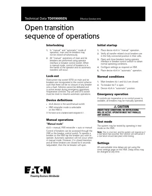
Open transition sequence of operationsInterlocking1. In “manual” and “automatic” mode ofoperation, main and tie breakers maynot be closed simultaneously.2. All “manual” operations of main and tiebreakers are performed using operatorinterface or breaker control switch. Whenin manual mode, control of breakers is inthe hands of the operator and no automatictransfers will occur.Lock-outOvercurrent trip switch (OTS) on main and tie breakers are incorporated in the control scheme such that there will be no closure of any breaker onto a fault. Scheme cannot be defeated andis active except during emergency operations (inoperative controls). Trip unit and OTS switch must be reset to resume automatic operations.Device definitions• 43-A device is the auto/manual switch• HMI retransfer mode is selectableon the HMI aa This feature can be a hardwired switch designated 43-1. Manual operations“Manual mode”43-A = manual, HMI retransfer = auto or manual Control of breakers can be accessed through the HMI or the breaker control switch. To operate a breaker on the HMI tap the breaker you wish to operate. Automatic operation will not occur when in manual mode. However, if in closed transition and all three breakers are closed for 5 seconds (adjustable), then the tie breaker will open.Initial startup1. Place device 43-A in “manual” operation.2. Verify all transfer related circuit breakers arein the fully connected position in their cells. 3. Open and close breakers (using operatorinterface or breaker control switch) to obtainnormal operating conditions.4. Configure settings as required on HMI.5. Place device 43-A in “automatic” operation.Normal conditions1. Main breakers 52-1 and 52-2 are closed.2. Tie breaker 52-T is open.3. Device 43-A in “automatic” position.Emergency operationIf controls are inoperative or no control power is available, all breakers may be manually operated.m CAUTIONUNDER THESE CONDITIONS, NO INTERLOCKING WILL BE ACTIVE. OPERATOR MUST NOT PARALLEL ANY SOURCES.Test modeThe system may be tested by operating in test mode on the HMI.ooee:N This is a live test, and the system will respond as if a real failure had occurred. Test function will self-cancel if a real failure should take place while testing.SettingsAll user-settable time delays are set using the timer settings page on the HMI. Delay times may be changed at any time.Eaoon1000 Eaton Boulevard Cleveland, OH 44122 United States © 2015 EatonAll Rights ReservedPrinted in USAPublication No. TD019005EN / Z17417 October 2015Eaton is a registered trademark.All other trademarks are propertyof their respective owners.Open transition s equence of operationsTechnical Data TD019005EN Effective October 2015Sequence of automatic operations “Open transition switching”43-A = auto, HMI retransfer = autoSee normal conditions for initial configuration.ooee:N Open-transition transfers between live sources are time-delayed in neutral, to prevent back-emf damage.A. Loss of utility power at main 52-11. Device 27/47-1 detects loss of normal voltage.2. Time delay 5 seconds (adjustable 0–60 seconds).3. Main 52-1 opens.4. Time delay 2 seconds (adjustable 0–10 seconds),and then tie breaker 52-T closes.B. Loss of utility power at main 52-21. Device 27/47-2 detects loss of normal voltage.2. Time delay 5 seconds (adjustable 0–60 seconds).3. Main 52-2 opens.4. Time delay 2 seconds (adjustable 0–10 seconds),and then tie breaker 52-T closes.C. Loss of utility power at main 52-1 and 52-2No action is taken.D. Return of normal voltage to main 52-1(following sequence “A” above)1. Device 27/47-1 detects normal voltage.2. Time delay 10 seconds (adjustable 0–60 seconds).3. Tie breaker 52-T opens.4. Time delay 2 seconds (adjustable 0–10 seconds),and then main 52-1 closes.E. Return of normal voltage to main 52-2(following sequence “B” above)1. Device 27/47-2 detects normal voltage.2. Time delay 10 seconds (adjustable 0–60 seconds).3. Tie breaker 52-T opens.4. Time delay 2 seconds (adjustable 0–10 seconds),and then main 52-1 closes.Sequence of automatic operations “Manual re-transfer”43-A = auto, HMI retransfer = manualSee normal conditions for initial configuration.ooee:N Retransfer following return of a failed source is initiated by operator. However, if second source fails, followed by return of the first-failed source, the system will transfer to the live source and remain single-ended.A. Loss of utility power at main 52-11. Device 27/47-1 detects loss of normal voltage.2. Time delay 5 seconds (adjustable 0–60 seconds).3. Main 52-1 opens.4. Time delay 2 seconds (adjustable 0–10 seconds),and then tie breaker 52-T closes.B. Loss of utility power at main 52-21. Device 27/47-2 detects loss of normal voltage.2. Time delay 5 seconds (adjustable 0–60 seconds).3. Main 52-2 opens.4. Time delay 2 seconds (adjustable 0–10 seconds),and then tie breaker 52-T closes.C. Loss of utility power at main 52-1 and 52-2No action is taken.D. Return of normal voltage to main 52-1(following sequence “A” above)No action is taken, requires manual transfer by operator:1. Set 43-A switch to manual.2. Use breaker control switches.Or1. Navigate to one-line screen on HMI.2. Press “initiate retransfer” button on HMI screen.E. Return of normal voltage to main 52-2(following sequence “B” above)No action is taken, requires manual transfer by operator:1. Set 43-A switch to manual.2. Use breaker control switches.Or1. Navigate to one-line screen on HMI.2. Press “initiate retransfer” button on HMI screen.。

第二章操作箱第一节概述1.断路器操作机构1.1断路器操作机构及控制回路操作机构是断路器本身附带的跳合闸传动装置,目前常用的机构有电磁操作机构、液压操作机构、弹簧操作机构、电动操作机构、气压操作机构等。
其中应用最为广泛的是电磁操作机构和液压操作机构。
断路器操作机构箱内电气控制回路包括:合闸和分闸操作回路,电气防跳回路,操作机构压力低闭锁回路,灭弧介质压力低闭锁回路,电机控制回路,加热回路,重合闸闭锁回路。
1.2断路器操作机构压力低的闭锁方式液压操作机构以高压油推动活塞实现合闸与分闸,其压力闭锁由高到低一般设有“重合闸闭锁”、“合闸闭锁”、“分闸闭锁”3级。
气动操作机构的分闸操作靠压缩空气来完成,而合闸操作则靠在分闸操作时储能的合闸弹簧来完成,其压力闭锁一般设有“重合闸闭锁”和“操作闭锁”2级。
弹簧操作机构设有“弹簧未储能”1级闭锁。
2.操作箱的组成2.1 操作箱内继电器组成2.1.1 监视断路器合闸回路的合闸位置继电器及监视断路器跳闸位置继电器。
2.1.2 防止断路器跳跃继电器。
2.1.3 手动合闸继电器。
2.1.4 压力监察或闭锁继电器。
2.1.5 手动跳闸继电器及保护相跳闸继电器。
2.1.6 一次重合闸脉冲回路。
2.1.7 辅助中间继电器。
2.1.8 跳闸信号继电器及备用信号继电器。
2.2 操作箱除了完成跳、合闸操作功能外,其输出触点还应完成的功能2.2.1 用于发出断路器位置不一致或非全相运行状态信号2.2.2 用于发出控制回路断线信号。
2.2.3 用于发出气(液)压力降低不允许跳闸信号。
2.2.4 用于发出气(液)压力降低到不允许重合闸信号。
2.2.5 用于发出断路器位置的远动信号。
2.2.6 由断路器位置继电器控制高频闭锁停信。
2.2.7 由断路器位置继电器控制高频相差三跳停信。
2.2.8 用于发出事故音响信号。
2.2.9 手动合闸时加速相间距离保护。
2.2.10 手动合闸时加速零序电流方向保护。

操作箱和断路器操作机构的功能要求一.《线路保护及辅助装置标准化设计规范》对操作箱的要求4.2.6对操作箱的相关要求a)两组操作电源的直流空气开关应设在操作箱所在屏(柜)内,不设置两组操作电源切换回路,操作箱应设有断路器合闸位置、跳闸位置和电源指示灯。
操作箱的防跳功能应方便取消,跳闸位置监视与合闸回路的连接应便于断开,端子按跳闸位置监视与合闸回路依次排列;b)为防止保护装置先上电而操作箱后上电时断路器位置不对应误启动重合闸,宜由操作箱对保护装置提供“闭锁重合闸”接点方式,不采用“断路器合后”接点的开入方式。
(注:保护装置先上电,TWJ跳位未开入,满足充电条件,保护装置的重合闸充电,操作箱后上电时,TWJ跳位闭合,断路器位置不对应误启动重合闸,为防止误起动重合闸,采用操作箱对保护装置提供的“闭锁重合闸”接点,与停用重合闸压板共用一个开入。
在操作箱后上电,TWJ跳位闭合时,“闭锁重合闸”接点也同时开入保护装置,保证了保护装置不误重合闸。
操作箱在手动跳闸或远跳以后,用双位置继电器KKJ(HHJ)置于跳后位置,起动中间继电器,输出并保持“闭锁重合闸”接点闭合、在手动合闸以后,双位置继电器KKJ(HHJ)置于合后位置,“闭锁重合闸”接点断开。
保护单相或三相跳闸,“闭锁重合闸”接点也处于断开位置,可以重合一次,如重合成功,保护装置可以再充电,如重合不成功再跳闸,断路器处于跳闸位置,TWJ跳位开入,保护装置的重合闸则不具备充电条件。
但此时双位置继电器KKJ (HHJ)仍为合后位置,需手动跳闸以后,KKJ(HHJ)处于跳后位置,才能重新闭锁重合闸。
重合闸充电在保护装置正常运行未起动时进行,重合闸控制字和把手投入、无TWJ、无压力低闭重、闭锁重合闸输入,经15秒后充电完成。
如采用“断路器合后”接点作为充电条件,手动跳闸闭锁重合闸仍然不能减少。
关于单操作箱、双操作箱、断路器为两个跳圈一个合圈的配合问题:单操作箱如仅配置一个双位置继电器KKJ(HHJ),一套合闸回路,两套跳闸回路。
继电保护--操作箱合闸、跳闸及防跳回路一、控制回路断路器控制回路,即是控制断路器分合的回路,电源为直流,一般为±110V多见。
现场实际中控制回路主要包括两个方面,继电保护操作箱中的控制回路与断路器本体的控制回路,两者经设计单位整合设计接线才能构成完整的断路器控制回路。
二、操作箱合闸回路(CZX-11G)4QD7-1SHJ手合接点闭合(ZHJ重合闸接点)-SHJA-4CD14-4CD12(或-1TBUJA-2TBUJA常闭接点)-开关辅助常闭接点-合闸线圈-负电4QD51。
跳位监视:如图1所示,4QD1-1HJA-1TWJA-2TWJA-3TWJA-4CD11-开关辅助接点-4QD51,在开关分位时导通,1HJA为发光二级管,当其点亮时表明开关合闸回路是通的,1TWJA、2TWJA、3TWJA为跳位监视继电器,开关分位时,该继电器是动作的,即常开接点闭合,常闭接点断开,注意1HJA点亮只代表跳位监视回路是通的,若4CD11、4CD12短接可代表4CD12后面的合闸回路是通的。
三、操作箱跳闸回路(CZX-11G)以A相跳闸回路为例,说明跳闸回路过程,虚线框内为断路器机构内简化操作回路。
4QD1、4QD7位操作正电源+110V,4QD51为操作负电源-110V。
跳闸过程:断路器为合位时,机构内断路器常开辅助接点(虚线框内)呈闭合状态,操作电源负电经合闸线圈、开关常闭辅助接点导通至4CD1、4CD2,手动及保护跳闸导通过程:正电4QD7-STJA手跳接点(或经TJQ、TJR、TJF一般为母差保护跳闸启动继电器接点;4QD19前一般是线路保护跳闸接点过来并经跳闸压板)-11TBIJA-12TBIJA-4CD2-开关辅助常开接点-分闸线圈-负电4QD51。
合位监视:如图2所示,4QD1-11HWJA-12HWJA-13HWJA-4CD1-4CD2-开关辅助接点-4QD51,在开关合位时导通;4QD1-1TJA-11TBIJA-11TBIJA-4CD2-开关辅助接点-4QD51,1TJA为发光二级管,当其点亮时表明开关跳闸回路是通的,11HWJA、12HWJA、13HWJA为合位监视继电器,开关合位时,该继电器是动作的,即常开接点闭合,常闭接点断开,注意1TJA点亮代表11TBIJA-12TBIJA-4CD2-开关辅助接点-4QD51的合闸回路是通的。
操作箱和断路器操作机构的功能要求一.《线路保护及辅助装置标准化设计规范》对操作箱的要求4.2.6对操作箱的相关要求a)两组操作电源的直流空气开关应设在操作箱所在屏(柜)内,不设置两组操作电源切换回路,操作箱应设有断路器合闸位置、跳闸位置和电源指示灯。
操作箱的防跳功能应方便取消,跳闸位置监视与合闸回路的连接应便于断开,端子按跳闸位置监视与合闸回路依次排列;b)为防止保护装置先上电而操作箱后上电时断路器位置不对应误启动重合闸,宜由操作箱对保护装置提供“闭锁重合闸”接点方式,不采用“断路器合后”接点的开入方式。
(注:保护装置先上电,TWJ跳位未开入,满足充电条件,保护装置的重合闸充电,操作箱后上电时,TWJ跳位闭合,断路器位置不对应误启动重合闸,为防止误起动重合闸,采用操作箱对保护装置提供的“闭锁重合闸”接点,与停用重合闸压板共用一个开入。
在操作箱后上电,TWJ跳位闭合时,“闭锁重合闸”接点也同时开入保护装置,保证了保护装置不误重合闸。
操作箱在手动跳闸或远跳以后,用双位置继电器KKJ(HHJ)置于跳后位置,起动中间继电器,输出并保持“闭锁重合闸”接点闭合、在手动合闸以后,双位置继电器KKJ(HHJ)置于合后位置,“闭锁重合闸”接点断开。
保护单相或三相跳闸,“闭锁重合闸”接点也处于断开位置,可以重合一次,如重合成功,保护装置可以再充电,如重合不成功再跳闸,断路器处于跳闸位置,TWJ跳位开入,保护装置的重合闸则不具备充电条件。
但此时双位置继电器KKJ (HHJ)仍为合后位置,需手动跳闸以后,KKJ(HHJ)处于跳后位置,才能重新闭锁重合闸。
重合闸充电在保护装置正常运行未起动时进行,重合闸控制字和把手投入、无TWJ、无压力低闭重、闭锁重合闸输入,经15秒后充电完成。
如采用“断路器合后”接点作为充电条件,手动跳闸闭锁重合闸仍然不能减少。
关于单操作箱、双操作箱、断路器为两个跳圈一个合圈的配合问题:单操作箱如仅配置一个双位置继电器KKJ(HHJ),一套合闸回路,两套跳闸回路。
第二章操作箱第一节概述1.断路器操作机构1.1断路器操作机构及控制回路操作机构是断路器本身附带的跳合闸传动装置,目前常用的机构有电磁操作机构、液压操作机构、弹簧操作机构、电动操作机构、气压操作机构等。
其中应用最为广泛的是电磁操作机构和液压操作机构。
断路器操作机构箱内电气控制回路包括:合闸和分闸操作回路,电气防跳回路,操作机构压力低闭锁回路,灭弧介质压力低闭锁回路,电机控制回路,加热回路,重合闸闭锁回路。
1.2断路器操作机构压力低的闭锁方式液压操作机构以高压油推动活塞实现合闸与分闸,其压力闭锁由高到低一般设有“重合闸闭锁”、“合闸闭锁”、“分闸闭锁”3级。
气动操作机构的分闸操作靠压缩空气来完成,而合闸操作则靠在分闸操作时储能的合闸弹簧来完成,其压力闭锁一般设有“重合闸闭锁”和“操作闭锁”2级。
弹簧操作机构设有“弹簧未储能”1级闭锁。
2.操作箱的组成2.1 操作箱内继电器组成2.1.1 监视断路器合闸回路的合闸位置继电器及监视断路器跳闸位置继电器。
2.1.2 防止断路器跳跃继电器。
2.1.3 手动合闸继电器。
2.1.4 压力监察或闭锁继电器。
2.1.5 手动跳闸继电器及保护相跳闸继电器。
2.1.6 一次重合闸脉冲回路。
2.1.7 辅助中间继电器。
2.1.8 跳闸信号继电器及备用信号继电器。
2.2 操作箱除了完成跳、合闸操作功能外,其输出触点还应完成的功能2.2.1 用于发出断路器位置不一致或非全相运行状态信号2.2.2 用于发出控制回路断线信号。
2.2.3 用于发出气(液)压力降低不允许跳闸信号。
2.2.4 用于发出气(液)压力降低到不允许重合闸信号。
2.2.5 用于发出断路器位置的远动信号。
2.2.6 由断路器位置继电器控制高频闭锁停信。
2.2.7 由断路器位置继电器控制高频相差三跳停信。
2.2.8 用于发出事故音响信号。
2.2.9 手动合闸时加速相间距离保护。
2.2.10 手动合闸时加速零序电流方向保护。