空气压缩机课程设计说明书
- 格式:doc
- 大小:595.63 KB
- 文档页数:26
编号:( )字 号本科生毕业设计(论文)题目:姓名: 学号: 班级:二〇一四年六月压缩机 王贵富 03071118 机自10-6班中国矿业大学本科生毕业设计姓名:罗俊学号:02021118 学院:机电工程学院专业:机械工程及自动化设计题目:压缩机专题:3L-15/12型空气压缩机指导教师:胡元职称:副教授二O一四年六月徐州中国矿业大学毕业设计任务书学院机电工程专业年级机自10-6班学生姓名罗俊任务下达日期:2014年3月1日毕业设计日期:2014年3月1日至2014年6月17日毕业设计题目:压缩机毕业设计主要内容和要求:(1)压缩机总体方案设计根据压缩机的用途,运转条件,排气量和排气压力,制造厂的可能性,驱动方式以及占地面积等条件,本设计压缩机选择L型往复活塞式。
(2)压缩机热力和动力计算压缩机的热力计算,是根据气体的压力、容积、和温度之间存在一定的关系,结合压缩机的具体特性和使用要求而进行,其目的是要求得最有利的热力参数(各级的排气压力、所耗动力)和适宜的主要结构尺寸(活塞行程、气缸直径)。
动力计算的目的在于计算压缩机的作用力,确定压缩机的所需额飞轮矩以及各种型式压缩机惯性力、惯性力矩的平衡状况。
初步设计压缩机所需的基础。
(3)压缩机气缸部分设计气缸是活塞式压缩机中组成压缩容积的主要部分。
根据压缩机所要达到的压力,排气量,压缩机的结构方案,压缩气体的种类,制造气缸的材料以及制造厂等条件,选择合适的类型。
(4)压缩机基本零部件设计压缩机由多个零部件组成,通过计算,设计基本尺寸,再对其进行强度校核,使设计的零部件能达到要求。
院长签字:指导教师签字:中国矿业大学毕业设计指导教师评阅书指导教师评语(①基础理论及基本技能的掌握;②独立解决实际问题的能力;③研究内容的理论依据和技术方法;④取得的主要成果及创新点;⑤工作态度及工作量;⑥总体评价及建议成绩;⑦存在问题;⑧是否同意答辩等):成绩:指导教师签字:年月日中国矿业大学毕业设计评阅教师评阅书指导教师评语(①基础理论及基本技能的掌握;②独立解决实际问题的能力;③研究内容的理论依据和技术方法;④取得的主要成果及创新点;⑤工作态度及工作量;⑥总体评价及建议成绩;⑦存在问题;⑧是否同意答辩等):成绩:评阅教师签字:年月日中国矿业大学毕业设计评阅教师评阅书评阅教师评语(①选题的意义;②基础理论及基本技能的掌握;③综合运用所学知识解决实际问题的能力;④工作量的大小;⑤取得的主要成果及创新点;⑥写作的规范程度;⑦总体评价及建议成绩;⑧存在问题;⑨是否同意答辩等):成绩:评阅教师签字:年月日中国矿业大学毕业设计答辩及综合成绩摘要空气压缩机是一种用来压缩空气、提高气体压力或输送气体的机械,是将原动机的机械能转化为压力能的工作机,简称为空压机。
TB-52型空气压缩机课程设计说明书吉林大学汽车工程学院七班课程设计说明书(三组)目录一.组长,组员名单。
二.任务安排及进度计划三.简述工作原理四.简述空气压缩机的拆装五.零、部件及标准间明细表六.工作总结七.参考文献组长:组员:任务安排及进度计划一.任务安排RW1……………………曾德临RW2……………………张璐蒋瀚颉RW3……………………孙铭RW4……………………李申童RW5……………………项泽林RW6……………………田波二.进度计划第一周:周一:上午,小组内部分清个人任务,并确定任务进度。
下午,组员一起动手拆装TB52型空气压缩机,确定其组成零件并了解其结构和工作原理。
并开始画自己任务内的草图。
周二:上午,保证按时到达,继续完成个人组内任务。
下午,必须完成组内草图任务。
周三到周五:在指导老师批完个人草图后,开始完成组内任务的CAD及CATIA。
将14张A4的CAD图按要求拼成1张A0或2张A1图,为打印做准备。
确定机体表达方案,测绘机体并画草图(A1)。
周六周日:继续赶进度。
第二周:周一周二:依据零件图装配图,确定装配图的表达方案,绘制装配图(白图,A1);上机绘制未完成的CAD及CATIA 图。
周三周四:完成CATIA装配图,生成轴测图,完成设计说明书。
打印所有CAD图。
并参加CATIA考试。
周五:绘图完成,归还各种工具和零部件。
三.简述工作原理工作原理:TB52型空气压缩机为用于小四轮拖拉机的刹车制动,也可作为充气喷漆的气源。
当皮带轮转动时,带动曲轴旋转,曲轴左端轴径穿在滑块孔中,而滑块在活塞杆下端的横孔可作横向滑动,因此曲轴旋转时,滑块在活塞杆横孔中作横向滑动的同时,带动活塞杆在垂直方向作上,下往复运动.当活塞下移时,气缸盖右边的进气阀门打开,左边的出气阀门关闭;当活塞上移时,气缸中的气被压出,由于皮带轮不停地旋转和上述过程不断地重复而得到压缩空气。
以下为装配示意图(零部件及标准件代号参见零部件及标准间表)四.简述压缩机的拆装顺序TB-52型空气压缩机的拆装:它由四个组件装成,由气缸盖组件,机体活塞组件,空气滤清器组件,曲轴组件.(1)气缸盖组件:气缸盖的右腔有进气孔,它与空气滤清器组件连接;左腔有出气孔,下面的阀片上,右边有进气阀门,左边有出气阀门.(2)机体活塞组件:它主要有机体(缸体),活塞,滑块,底盖和探油针以及放油丝堵组成,活塞上有三个活塞环.(3)空气滤清器组件:它装在进气口处,内有空气过滤网,此组件不拆也不装.(4)曲轴组件:它包括曲轴,皮带轮,两副球轴承,轴承座,油孔,密封圈以及两个轴承卡簧.小的卡在轴上,大的卡在轴承座上.一般机器拆装的顺序是:先拆下的零件要最后装,最后拆下的零件要先装.注意事项:(1)熟悉空气压缩机的结构及作用.(2)记住零部件数量,拆开后按顺序放置整齐,不可随意乱扔.(3)选用工具应恰当,并应正确使用.如扳手不可当锤用,螺丝刀不能当撬板五.零、部件及标准件明细表序号名称材料序号名称材料1 阀板HT200 12 油尺铁丝2 阀板上垫片橡胶石棉板13 油尺座Q2353 阀板下垫片橡胶石棉板14 油尺垫片耐油橡胶4 阀片钢板15 油尺组件5 阀板组件16 曲轴QT600-3 6 放气塞Q235 17 轴承座HT2007 轴承座垫片橡胶石棉板18 皮带轮HT2008 滑块粉末冶金19 曲轴组件9 底盖HT20020 活塞HT20010 底盖垫片橡胶石棉板21 汽缸盖HT20011 油塞垫片A1 22 机体HT200名称数量标准代号备注(序号) 轴承6204 1 GB/T 276-2008 23轴承6205 1 GB/T 276-2008 24挡圈48 1 GB 893.1-1986 25挡圈40 1 GB 893.1-1986 26挡圈20 1 GB 894.1-1986 27密封圈B20*40*7 1 GB/T9877.1-198828螺栓M8*45 4 GB/T5782-2000 29 螺栓M8*20 4 GB/T5782-2000 30 螺栓M8*16 4 GB/T5782-2000 31 垫圈8 12 GB/T 93-1987 32 螺母M12 1 GB/T6170-2000 33 垫圈12 1 GB/T97.1-2000 34 垫圈12 1 GB/T 93-1987 35 油塞M8*1 1 JB/ZQ4450-1986 36空气过滤器 1 37气环 2 GB/T9440-1988 38油环 1 GB/T9440-1988 39螺钉M5*5 3 GB/T67-1985 40垫圈5 3 GB/T97.1-2000 41螺钉M6*16 2 GB/T65-2000 42垫圈6 2 GB/T93-1987 43六.工作总结为期两周的课程设计已经结束了,本组同学在老师指导下按要求完成了任务。
1引言毕业设计是学完所有课程后应用四年所学到的课本知识及课外的知识而进行的综合性、开放性的训练,是培养学生工程意识和创新能力的重要环节,也是考查学生四年学习成果的重要途径。
此次毕业设计的主要内容是通过对活塞式压缩机热力性能和动力性能的计算,完成压缩机的校核和选型工作。
通过近两个月的设计过程,对于我掌握过程流体机械选型基本方法、基本步骤和基本原则起到了明显的效果,达到了预期的训练目的。
同时,通过毕业设计环节,使我的计算机应用能力得到了提高,培养了我的设计能力和解决实际问题的能力。
毕业设计要求学生正确运用和查阅与本课题相关的设计标准、规范、手册、图册等技术资料,独立的进行理论计算、结构计算、绘制工程图样、编写设计说明书等。
掌握机械设计的基本要求、基本方法、基本步骤,为走向工作岗位打下坚实的基础。
V-0.17/8空气压缩机设计的主要任务是了解空气压缩机的基本原理与结构类型,着重了解和掌握活塞式空气压缩机的基本原理、组成结构、材料、制造加工工艺、冷却润滑方式等。
1.1设计参数题目:V-0.17/8空气压缩机设计排气压力=0.8MPa吸气压力Ps=0.1MPa排气量Q=0.17m3/min转速n=2840r/min1.2 空气压缩机的结构及工作原理空气压缩机是气源装置中的主体,它是将原动机(通常是电动机)的机械能转换成气体压力能的装置,是压缩空气的气压发生装置。
空气压缩机的种类很多,按工作原理可分为容积式压缩机,速度式压缩机,容积式压缩机的工作原理是压缩气体的体积,使单位体积内气体分子的密度增加以提高压缩空气的压力;速度式压缩机的工作原理是提高气体分子的运动速度,使气体分子具有的动能转化为气体的压力能,从而提高压缩空气的压力。
本机属于容积式空气压缩机。
往复式空气压缩机主要有曲轴连杆活塞式、曲柄连杆活塞式和曲柄滑管式三种形式。
其主要由活塞、气缸、曲轴、连杆、吸气阀片和排气阀片等组成。
连杆小头主要通过活塞销与活塞相连,而连杆大头套在曲轴的曲轴柄部分,曲轴由带轮带动旋转,气缸顶部安装有阀板组件。
目录一、热力学计算 (2)1.1初步确定压力比及名义压力 (2)1.2初步计算各级排气温度 (3)1.3计算各级排气系数 (4)1.4确定气缸行程容积: (6)1.5确定气缸直径 (7)1.6修正压力及压力比 (9)1.7实际压力与压力比 (9)1.8各级温度 (10)1.9计算止点活塞力 (10)1.10复核实际排气量 (11)1.11计算指示功率 (11)1.12计算功率 (12)1.13比功率计算 (12)二、第一级缸动力分析 (14)2.1曲柄长度: (14)2.2余隙容积折合的长度 (14)2.3气体力分析 (14)2.4摩擦力的计算 (17)2.5往复运动质量的计算 (17)2.6总活塞力的计算 (18)2.7切向力计算 (18)三、第二级缸图解法 (20)3.1运动曲线 (20)3.2Ⅱ各级气缸指示图 (20)3.3作气体力展开图 (21)3.4作切向力图 (22)参考文献 (24)一、热力学计算1.1 初步确定压力比及名义压力 (1) 两级压缩总压力比964.8009.1045.912===s d P P ε 按等压力比分配原则确定各级压力比:0.321===εεε(2) 各级名义进、排气压力如下:027.30.3009.1111=⨯==εs d P P 081.90.3027.3222=⨯==εs d P P式中:ε——两级压缩总压力比1S P ——第一级名义进气压力1d P ——第一级名义排气压力 2S P ——第二级名义进气压力2d P ——第二级名义排气压力1ε——一级压力比2ε——二级压力比故各级名义进、排气压力如下表:1.2 初步计算各级排气温度第一级进气温度:K T s 3001=第一级排气温度: 由公式kk s d T T 1-=ε可得:K T T kk s d 4110.33004.114.1111=⨯==--ε由于介质是空气取k=1.4。
第二级进气温度:K T s 3152=第二级排气温度:K T T kk s d 4310.33154.114.1122=⨯==--ε式中:1S T ——第一级进气温度 1d T ——第一级排气温度2S T ——第二级进气温度 2d T ——第二级排气温度故各级名义排气温度如下表:1.3 计算各级排气系数因为压缩机工作压力不高,介质为空气,全部计算可按理想气体处理。
压缩机说明书压缩机说明书篇一:空气压缩机使用说明书空气压缩机使用说明书一、操作注意事项:1、压缩机必须定期检修,并保证在良好工作状态下工作。
2、在压缩机组运行前,必须注意不可有人在机器上进行检修工作。
3、压缩机应在技术规范规定的范围内运行。
4、不可以在可能吸入易燃、有毒或腐蚀性蒸汽或气体的环境中运行压缩机。
5、注意人不可以接触管路系统,尤其是排气管或是在运行中的高温部件。
6、压缩机组运行时,操作人员不可做其他别的工作,以适时监控压缩机组的运行状态。
二、维修工作注意事项:1、维修工作只可在停机并完全放空的压缩机上运行。
若有必要,将压缩机系统内的高压气体放空。
首先应断开电源控制箱的总闸,为了防止误开机组,应将总闸锁上,或者贴一张相应的指示标签。
2、开始工作前,应全部打开凝液分离器上的手动排水阀,使得压缩机组完全放空,没有压力。
3、每次修理或改造安全设备时,如果要求有修改后检查合格证的,必须经有关监测主管部门重新验收认可。
4、在压缩机组上,只可用原装备件和推荐使用的零部件进行维修。
5、在维修时要严格保持清洁,拆下的零件应置于干净的地方,并对不同的零件采取用布、纸或胶布遮盖起来,以防尘污。
6、维修后,检查一下确定没有工具,零部件和抹布留在压缩机组上面或者里面。
7、压缩机组完全降温前,决不可用易燃溶剂清洗零部件。
零部件用溶剂清洗后,然后用压缩空气将零部件吹洗干净。
8、用压缩空气吹设备时,应十分小心,并戴护目镜。
三、压缩机的主要性能参数:a、公称容积流量: 3m3/minb、吸气压力: 0.1MPac、额定排气压力: 4.0MPad、吸气温度:≤45℃e、各级排气温度:<180℃f、输气温度:≤50℃g、压缩介质:空气h、冷却水耗量:≥3.5 m3/hi、润滑油温度:≤70℃j、气缸直径:一级φ285mm二级φ155mm三级φ75mmk、活塞行程: 95mml、转速:740r/minm、配备动力: Y280M-8,740r/min,450KW, AC380V/50Hz IP44 B3n、压缩机外形尺寸(长×宽×高):~2350×1900×1500(mm)o、全机重量:2500kgp、震动烈度:≤28.0q、各级排气压力:一级排气压力:0.27~0.37MPa二级排气压力:1.2~1.39MPa三级排气压力:4.0MPa四、气路系统:气路系统的作用,主要是将气体引向压缩机,经压缩机各级压缩之后,再引向使用场所,本机的主要气路流程示意如下:其中空气滤清器、一级气缸、一级冷却器、二级气缸、二级冷却器、二级油水分离器、三级气缸、三级冷却器、三级油水分离器和以上部件连接的管道组成压缩机的气路主管路,排除油、水用的排污管路以及连接压力表的管路和控制管路等组成压缩机气路的辅助管路;用户在使用该机前,必须增加后续管道和阀门分别与送气接头、排污接头相连接,以备把压缩空气送至使用场所和把油水引至合适的位置排放掉,本机的排污是自动排污,排放的时间间隔约为20~30min排放一次,排放时间约为10s,用户可根据当地的空气湿度进行适当的调整。
目录之迟辟智美创作1、目标2、参考文件2.1、编码及标准2.2、项目规范3、设计条件4、设计要求4.1、概述4.2、空气和油系统4.3、冷却和冷凝系统4.4、调试系统4.5、螺杆式压缩机控制系统5、仪器5.1、概述5.2、供应商的仪器供应范围6、电气设备7、车间检验和测试1、目标本规范界说的螺杆式空气压缩机最低限度的设计、资料,制作,测试、检验,运行,性能和运输适用于米桑油田的开发项目.供应商应提出本规范没有规定的所有其他项目的标准惯例.供应商有责任确保设计和资料的供应是依照适用的伊拉克法律&法规,文件,编码&标准,而且设计条件在本规范中有涉及到.2、参考文件下面列出的最新版本的编码,标准和规范的使用部份(包括附录和文档引用)应是本规范的一个完整部份.参考抵触的情况下,供应商应在报价单中提交书面廓清说明.否则,按最严厉的要求供应.2.1、编码和标准编码和标准应是最新版本.(1)API 619回旋式容积压缩机用于石油,chimal、天然气行业.2.2、项目规范以下文件涉及仪器、电气和机械设计、和资料的结够及制作.他们弥补本规范并装订.理解申请的更加完整的清单适用的文件,项目设计数据“”空气压缩机的基础设计“”设备噪音值“”整装设备一般规范“”滑动装置的封装元件结构要求的一般规范“”调节阀门工艺规范“”管道预制规范“”通用仪器规范“”仪器和整装设备控制规范“”接地与照明系统的规范“”高压马达的规范“”油漆规范“”管道资料规范3、设计条件螺杆式压缩机依照数据表中的数据设计.过滤器完全整合在压缩机的主体中.这“一体式”特性减少了装置所属空间而且很好的节约了装置本钱.4、设计要求4.1、概述4.1.1、DD过滤器压缩机须提供完整的DD类型的过滤器,用以限制固体颗粒和油的残留物.通过整合DD过滤器,压缩机输送空气质量根据ISO 8573-1,第2.4.2部份.4.1.2、油分离装置油分离装置将油残留物从冷凝物中分离.清洁水可以不做任何后期处置排入到下水管道.分离出的油通过一般规则来处置.4.1.3、电子下水管道电子下水管道要保证冷凝物的适当排出,而且阻止水流进入到空气压缩机的内部.对排水过程的任何故障,在稳压器上,显示器生成一条警告消息显示在显示屏.4.1.4、集油架此架子装置在机器下面,收集偶尔泄露的油和防止油溅到空中上.4.1.5、调节控制调节控制系统的设计是为了维持一个净压力带通过推动进去口空气,因此减少50%-100%的空气流动.4.1.6、重型进气过滤器一个两级重型空气吸收过滤器应提供并允许压缩机在严重污染的环境中(如当下或者矿工财富)运行.年夜型的粉尘颗粒物在过滤器的第一级被吸收.过滤器的效率在1千分尺(0.0004)上为99%,在3千分尺(0.0012in)是99.9%.4.1.7、入口雨呵护雨呵护阻止雨水进入到机器.同时,呵护稳压器上的电子显示屏不受日晒雨淋.4.1.8、高的周围温度在湿润和高的周围温度条件下,压缩机要特别设计能够连续运行.4.1.9、相位继电器相位继电器阻止机电马达的选择参照4.1.10中热马达呵护.4.1.10、热马达呵护机电马达的热呵护.传感器装置在马达上,两个用于丈量轴承的温度,三个用于丈量窗户的温度.读数会在稳压器的电子显示屏上显示.如果其中一个温度超越停车升温设置,在显示屏上会有消息,并通用的LED警示灯会亮起.4.1.11、添加HD Roto-FluidsHD Roto-Fluids 是一种特殊的,长寿命的润滑剂,用于油注入的螺杆式压缩机.它提供更好的冷却和扩年夜了油间距. 4.1.12、冷却机压缩机配备空气冷却机4.1.13、SPM检测提供若干振动传感器,用在潜水机电和压缩机元件上.4.2 空气和油系统4.2.1 空气流量空气吸入通过过滤器和卸荷在压缩机构件中被压缩.压缩的空气通过止回阀被排到空气接收器/油分离器,在那里油将从压缩的空气中分离.空气通过最小压力阀被送到空气冷却器.在封装压缩机上,冷却器空气通过冷凝槽和排气口排到年夜气中.止回阀阻止压缩的空气回流.最小压力阀阻止接收器的压力降到最小压力以下.此阀门有个内置止回阀.4.2.2、油系统通过油冷却器,过滤器和油截止阀空气压力迫使来自接收器的油到压缩机元件和润滑油点.当压缩机停止时,截止阀阻止压缩机元件被油淹没.阀门支路油冷却器当凝视压缩机从冰凉的条件,因此确保快速变暖的石油正常工作温度.在年夜大都油中接收到的空气源自空气离心筒.几乎说有的油渣均通过分离元件移除.4.3、冷却和冷凝系统4.3.1、冷凝物排水系统冷凝槽装置在空气冷却器下方,用来阻止冷凝物进入到空气排出口管道.槽要提供浮球阀用来自动排泄冷凝物,以及手动排水阀.4.3.2、冷却系统在空气冷却压缩机上,空气冷却器和油冷却器时通过风机冷却,包括油和空气相结合的冷却器.4.4、调节系统4.4.1、调节系统压缩机是由电子稳压器控制.稳压器坚持净压力在可编纂压力极限内,通过依据空气消耗量自动下载和卸载压缩量.它还呵护压缩机和服务于设施的监测器.4.4.2、卸载系统如果空气消耗量小于压缩机的空气输送量,净压力增加.当净压力到达工作压力(卸载压力)上限时,电磁阀将不工作.电磁阀的活塞切断朝腔体内供应的接收压力.通过电磁阀,控制以后腔体内压力是排放到年夜气中.卸荷阀通过弹簧弹力关闭.阀门被往下推,通过弹性和通道朝进气口释放接收器压力.被挤出的小流量空气通过孔洞和通道,从接收器被吹到进气口.压缩机运行卸载,空气输送停止(0%).4.4.3、装载当净压力供应减少到小于工作压力(朝腔内装载的压力)上限时,电磁阀的活塞顶着弹簧弹力向上运动.电磁阀的活塞翻开,接收压力像腔内供应.卸荷阀顶着弹簧弹力开启.接收压力也推着阀门向上,关闭排气通道.压缩机运行装载,空气输送重新开始(100%).4.5、螺杆式压缩控制系统螺杆式压缩机应有以下功能:(1)、控制压缩机(2)、呵护压缩机(3)、服务设施的监测配件(4)、电压故障(无举措)之后自动重启(5)、可允许启动4.5.1、自动控制压缩机运行在可编纂的极限间稳压器维持净压力通过自动装载和卸载压缩机.要考虑可编纂数值的设定,如卸载和装载压力,最低停止时间和最年夜马达启动值.当净压力减少时,稳压器停止压缩机,只要有可能,以减少能源消耗和能自动重启.如果预期的卸载和装载太短,压缩机要坚持运行状态以防止太短的停滞期.4.5.2、压缩机呵护在压缩机上要提供若干传感器.如果这些丈量值中的一个超越规定的关闭值,压缩机将停止运行.这将在显示屏上显示,而且LED警示灯将会闪烁,纠正故障和重置信息.如果这些丈量值中的一个超越规定的关闭值,信息将在显示屏上显示而且LED警示灯将会亮起.4.5.3、调养警告一些调养把持被分组(称A,B,C……).每个品级都有一个规定的时间间隔.如果超越时间间隔,信息将显示以警示把持员执行属于此品级的调养把持.4.5.4、电压故障后自动重启稳压器有个内置的功能用来自动重启,如果电压故障后电压重新恢复.对生产的压缩机,这个功能是闲置的,如果要求,此功能能够启动.4.5.4、允许启动在启动指令之后,将执行允许启动.如果在压缩机元件上的油注入压力超越规定值,压缩机将不会启动.5、仪器5.1、概述仪器的最低要求:供应商的检测标准应能普遍用于设计和提供的仪器规范.可是,供应商应遵循以下标准化要求或者是备件库存最优化目的.(1)、仪器符号- 电气符号 DC 4 – 20 Ma- 气压符号 0.2 –1.0 kg/cm2- 热电偶或者是RTD带有电子变频器 DC 4 – 20 mA- 现场控制器 0.2 –1.0 kg/cm2(2)、现场控制器- 仪器规范按每个供应商标准- 类型和结构按每个供应商标准- 油漆及颜色淡绿- 电缆按每个供应商标准- 外部电缆终端接线盒 Hamonica 类型 - 外部电缆终端接线头圆字头类型- 外部电缆的电缆标识表记标帜说明连接终真个数值5.2、供应商仪器供应范围对螺杆式压缩机的把持、控制和平安防护,供应商在限制范围内提供以下仪器.(1)、所有现场仪器(数字仪器、控制阀、防静电阀门、泄压阀、MOV’s、压力平安阀,热平安阀等)(2)、附件(脉冲线、接线盒、电缆盘、导管、电缆腺体、配件等)(3)、现场光灯仪器盘(4)、封装电池极限内有效分配(5)、文件资料(6)、通过仪器清单和P&ID,供应商应在建议书中说明仪器供应范围.6、电气设备所有的电气设备或电气仪器应符合工业编码和标准,如IEC、NEMA.7、车间检验和测试(1)、所有资料和产物应在车间被检验和测试根据规范和在“车间检验和测试要求表”附件1中列出的项目.供应商应提交其检验建议和测试项目清单和与报价单一起.(2)、由公司检验和见证测试将不会减轻供应商应在资料,设备、工艺和其他方面的责任.(3)、公司或其他指定代表有权审查和检查生产、测试或在供应商车间其他与清单上设备有关的活动或者二级供应商的设备.供应商有责任安插他们的二级供货商的关于他们设备的使用权.。
压缩空气教学设计压缩空气是物理学领域的一个重要概念,也是科学课程中常见的内容之一。
通过生动的教学设计,可以帮助学生更好地理解压缩空气的原理和应用。
本文将介绍一种针对中学物理课程的压缩空气教学设计,旨在提高学生的学习兴趣和理解能力。
一、实验目的本次教学实验的主要目的是让学生观察和探究压缩空气的性质,并理解其应用原理。
二、实验材料1. 一个空气压缩机2. 一个透明塑料瓶3. 一根橡皮管4. 一片塑料薄膜5. 一小段塑料吸管6. 针和胶布三、实验步骤1. 将透明塑料瓶的底部截去,制作成一个开口朝下的漏斗。
2. 将塑料薄膜覆盖在瓶口上,并用橡皮管连接到空气压缩机。
3. 打开空气压缩机,观察漏斗内的塑料薄膜发生的变化。
4. 用针在塑料薄膜上戳一个小孔,并用胶布封住。
5. 将塑料吸管插入瓶中,让学生用嘴吹气,观察塑料薄膜的变化。
四、实验原理利用空气压缩机将空气压缩注入透明塑料瓶中,可以观察到瓶内的压缩空气的性质。
当塑料薄膜封住瓶口时,空气无法释放,从而使得塑料薄膜呈现鼓起的状态。
当在塑料薄膜上戳一个小孔时,压缩空气会通过小孔逸出,使得塑料薄膜重新平整。
接着让学生用嘴吹气,可以观察到由于嘴吹气所添加的新的压缩空气,塑料薄膜再次鼓起。
五、实验拓展1. 对比不同材质的塑料薄膜,观察它们在压缩空气下的变化。
2. 探究不同压力下,塑料薄膜鼓起和收缩的差异。
3. 分析压缩空气在气垫悬浮、火箭推进器等方面的应用。
六、实验总结通过本次实验,学生们可以直观地观察到压缩空气的性质和应用,并通过实践操作加深对物理原理的理解。
教师可以引导学生进行讨论和总结,进一步巩固知识。
以上是一种针对中学物理课程的压缩空气教学设计。
通过生动的实验演示,学生可以直观地了解到压缩空气的原理和应用。
这样的教学设计不仅能提高学生的学习兴趣,还能帮助他们更好地理解和掌握相关知识。
教育的目的就是为了激发学生的求知欲和创造力,通过科学的教学设计,我们能够更好地实现这一目标。
AIR COMPRESSOROPERATING INSTRUCTIONSPLEASE READ THIS MANUAL BEFORE INSTALLING OR USING YOUR AIR COMPRESSOR UNIT. IT CONTAINS VALUABLE INFORMATION THAT WILL HELP YOU IN THE RECEIVING, INSTALLATION, USE, AND MAINTENANCE OF THE UNIT. KEEP THIS BOOKLET IN A SAFE PLACE FOR FUTURE REFERENCE.COMPRESSOR IDENTIFICATIONPlease fill in the appropriate information in the spaces provided below. These numbers will allow us to correctly identify your compressor in the event you need service or parts.UNIT MODEL NUMBER: ___________________________ (i.e. OLT-5080) (Located on Base of Air Receiver or Air Receiver – White Label)UNIT SERIAL (MFG.) NUMBER: ___________________________ (i.e. PLP-040902780) (Located on Base of Air Receiver or Air Receiver – White Label)PUMP MODEL NUMBER: ___________________________ (i.e. OLT-50) (Located on Front or Side of Compressor Pump)PUMP SERIAL NUMBER: ___________________________ (i.e. 23045) (Located on Front or Side of Compressor Pump – Professional Series Compressor Pumps do not have Serial Numbers)ELECTRICS: ___________________________ (i.e. 230V/60Hz/1PH) (Located on Nameplate of Motor)COMPRESSOR DISTRIBUTOR ________________________________________________ (Who You Bought the Air Compressor From)TABLE OF CONTENTS•COMPRESSOR IDENTIFICATION……………………………...………Front Cover •TABLE OF CONTENTS...............................................................................Inside Front Cover •SAFETY PRECAUTIONS……………………...………………….………pg. 1-2•GENERAL DESCRIPTION OF AIR COMPRESSOR.………...……….pg. 2•INSPECTION OF AIR COMPRESSOR……...………………...………...pg. 2•GENERAL REQUIREMENTS……………………...…………………….pg. 3•INSTALLATION – MECHANICAL……………………...………………pg. 3•INSTALLATION – ELECTRICAL………………………...……………..pg. 3-4•INITIAL START–UP PROCEDURES.............…………...……………...pg. 4-5•PREVENTATIVE MAINTENANCE……………………...……………...pg. 5•TROUBLESHOOTING………………………………...….………………pg. 6-7•WARRANTY…………………………………………...…..………………Back CoverSAFETY PRECAUTIONSPlease familiarize yourself with the following information for preventing damage to your air compressor unit and injury to the operator and/or property damage.ELECTRICAL HAZARDNever use the air compressor without connection to a properly grounded outlet with the specified voltage and fuse protection. Do not use the compressor in a wet or explosive environment, as the electrical components on the compressor are general purpose and the motors are open drip proof. The compressor must be located a minimum of 20 feet (6.1 metres) from any source of potentially explosive vapours. Never attempt maintenance or adjustment with power connected or while the equipment is in operation.TANK SAFETY VALVEThe safety valve is factory installed to prevent the air receiver from damage should malfunction occur in the pressure switch. It is factory set at a specific limit for your particular model, and should never be tampered with. Adjustment by user will automatically void warranty.PRESSURE SWITCHThe air compressor switch is set at the factory for optimum performance of your particular model. Never bypass or remove this switch as serious damage to equipment or personal injury could result from too high of pressure.MOTOR AND COMPRESSOR PUMPAir compressors become hot while in operation. Never touch the motor, compressor pump, and/or discharge tubing while in operation or immediately after operation. Touching these areas may cause severe burns. The compressor automatically operates while the power is on. Do not come into contact with moving parts. Shut off all power to the unit before attempting to repair or maintain the compressor. Never operate the compressor with the belt guard removed.COMPRESSED AIR CAUTIONCompressed air from the unit may contain poisonous vapours which are not suitable for inhaling and could be harmful to your health. Never directly inhale compressed air produced by the compressor. Always use proper filtration, carbon monoxide monitor and quality tested air for breathing applications from a compressor. Ensure your breathing apparatus meets NIOSH and OSHA requirements. Always wear proper safety equipment while using compressed air.AIR RECEIVEROver pressurizing the air receiver could cause an explosion or rupture. To protect from over pressurizing a factory preset safety valve is included. Do not remove, make adjustments or substitutions for this valve. Occasionally pull the ring on the valve to make sure that the valve operates freely. If the valve does not operate freely, it must be replaced.Never weld to, drill, or change the air receiver in any way. If any of the above conditions are changed or tampered with this may result in voiding of the manufacturer’s warranty.GENERAL DESCRIPTION OF AIR COMPRESSORTo compress air, the piston moves up and down in the cylinder. During the downstroke, air is drawn in through the inlet valve. The discharge valve remains closed. During the upstroke of the piston, air is compressed. The inlet valve closes and compressed air is forced out through the discharge valve, through the discharge tube, through the check valve and into the air receiver. Working air is not available until the compressor has raised the air receiver pressure above the requirement at the air service connection. The air inlet filter openings must be kept clear of obstructions.INSPECTION OF AIR COMPRESSOREach Omega Air Compressor is factory tested and inspected before shipment. Every attempt is made to ensure safe and complete shipment of our products. Freight damage or misplacement of goods may occur. Shipments of Omega products are the property of the consignee when the products leave our facility. Omega Compressors is not responsible for any damages or shortages caused to the products after it has left our facility.It is the responsibility of the receiver of the goods to ensure the product has been received in full and has arrived in suitable condition. Damage may not be visible at the time of off-loading, but may only become apparent upon unpacking or start-up.Should there be shortages or damages in shipment to the product, A Loss or Damage Claim should be submitted to the carrier and supported by copies of the bill of lading, invoice, estimate to repair and a damage report. Do not discard any of the products or packaging as they may be required by the carrier for inspection.GENERAL REQUIREMENTSAs the owner of a new Omega Air Compressor Unit, it is your responsibility to ensure it is installed correctly, as well as maintained and serviced on a regular basis. Information has been included in this booklet outlining the suggested air compressor maintenance schedules and a trouble shooting guide. It is important that you read this information and keep it in a safe place for future reference.INSTALLATION - MECHANICALLocate the air compressor in a clean, dry and well ventilated area. The air compressor should be located 12 to 18 inches away from walls or any other obstruction that would interfere with the air flow through the pump flywheel. If possible, the air compressor should be located in a separate room or area with an air intake or fan positioned on an outside wall for maximum air flow and cooling. The air compressor is designed with heat dissipation fins that allow for proper cooling. Keep the fins and other components clean. A clean compressor runs cooler and provides longer service. Allow room for easy access to the air compressor for maintenance and service work.For permanent installation, the compressor may be bolted to the floor through holes provided in the compressor feet. Shims and vibration isolators or vibration pads must be used to level the compressor before bolting it to the floor. Severe vibration will result when the compressor is bolted down tightly and the feet are not level. This can lead to welds cracking or fatigue failure of the air receiver.Omega Compressors offers vibration isolators or vibration pads, flex hoses, electronic auto drains or pneumatic auto drains along with a host of other accessories such as filters and refrigerated air dryers etc. to provide reliable clean dry compressed air. Ask your local Omega distributor for details on all our accessories.INSTALLATION - ELECTRICALIt is your responsibility to ensure that the Air Compressor Unit is electrically connected in a safe and correct manner. Any electrical work should be carried out by a competent electrician and installed in a way which meets all applicable codes and regulations. A magnetic starter must be an integral part of the air compressor except on contractor and professional series units. A magnetic starter may be supplied with your unit from the factory.Failure to connect the air compressor correctly to your buildings electrical services may result in serious personal injury or damage to the equipment.Please note that under normal conditions, the air compressor will operate intermittently. Should it be necessary to service the air compressor ensure the power source has been shut down. This must be done to prevent personal injury or damage to the unit.Do not attempt to operate the air compressor unit without first checking the oil level in the pump. Add oil as required. Serious damage may result from use without oil.MOTORSWiring must be done in a manner that full voltage nameplate +/- 10% is available at the motor terminals during startup. Use of an incorrect electric motor for your particular building service will result in premature motor failure and is not covered by Omega Compressors or Motor manufacturer’s warranty. The warranty that exists on the electric motor is that of the original manufacturer. In the event of a motor failure contact your Omega Distributor or Service Centre for the location of the nearest authorized motor service centre.PRESSURE SWITCHESThe pressure switch located on the compressor unit acts as a pilot device activating the coil on the magnetic starter except on contractor and professional units where the pressure switch would act as a pilot device activating the motor. The pressure switch cut in/cut out has been preset at the factory. Do not tamper with the settings. Consult your local distributor or service centre should the switch not be operating properly.PUMP ROTATIONThe compressor is to be wired in a manner that the rotation of the flywheel causes the air to be blown over the pump. This allows the pump to cool properly. When facing the nameplate side of the unit the flywheel must rotate clockwise unless otherwise noted on the unit with an arrow on the belt guard or motor.INITIAL START-UP PROCEDURE1.)Check to see that nuts and bolts are all snug. This must be done, as somefasteners may become loose in transit.2.)Check to see if the belt is installed properly, with proper tension.3.)Check belt tightness so that when pressure is applied at the centre, there is ½”slack.4.)Check that compressor is fixed on a strong, stable level base.5.)Check that air filter is clean.6.)Do not place any materials on or against the belt guard, or the compressor unititself. Placing materials there will limit the cooling of the compressor and could lead to premature failure.7.)Turn the compressor “on” momentarily by positioning the fused disconnect inthe “on” position. Ensure that the flywheel is turning in the correct position.See “PUMP ROTATION” (page 4). On compressors with three phase power, adjust the wiring at the motor terminals if the rotation is incorrect. Refer to the wiring diagram on or in the motor terminal box.8.)Open the air receiver outlet ball valve and start the unit. Ensure air is escapingto atmosphere. After running the compressor unit for twenty minutes, close the ball valve, and allow the unit to reach maximum operating pressure. Ensure that the compressor shuts down at the pre-set maximum pressure, and the headpressure is released through either the pressure switch or the CPR on the front of the pump.9.)Check the air compressor and piping systems for air leaks, and correct asrequired.10.)Shut off all power to the air compressor before attempting any repair ormaintenance.11.)Your compressor is ready for use.PREVENTATIVE MAINTENANCEBefore doing any maintenance or adjustments to your air compressor, the following safety precautions should be taken.1.)DISCONNECT ELECTRICAL POWER.2.)DRAIN AIR RECEIVER OF AIR PRESSURE.DAILY CHECK LIST1.)Drain Condensation from Air Receiver.2.)Check for Any Unusual Noise or Vibration.3.)Be Sure All Nuts and Bolts are Tight.WEEKLY CHECK LIST1.)Clean Air Filter by Opening Air Filter Cap. Replace Filter if Necessary.QUATERLY OR 300 HOUR CHECK LIST1.)Change Filter Element.2.)Check Condition and Alignment of Belt, Flywheel and Motor Pulley. Adjust BeltTension if Necessary or Replace Belt if Worn.3.)Check Safety Valve.4.)Check Pressure Switch Unloader to Ensure Compressor Head Unloads WheneverMotor Shuts Down.5.)Clean and Blow Off Pump Fins and Motor.6.)Inspect Air System for Leaks, by Applying Soapy Water to All Joints. TightenJoints if Leakages are Observed.TROUBLE SHOOTING GUIDE CONDITION CAUSE CORRECTIVE ACTION Compressor Will Not Start. 1.) Fuse blown or circuit breaker tripped.2.) Loose electrical connections.3.) Overheated motor. 1.) Check for cause of blown fuse or breaker and replace or reset. 2.) Check wiring connections. 3.) Press reset button or wait for automatic reset. Check belt tension. Low Pressure 1.) Air leak in safety valve. 2.) Loose tube of fittings. 3.) Restricted air filter.4.) V-Belt loose.5.) Defective check valve 1.) Check valve manually by pulling upward on ring. If condition persists replace valve. 2.) Tighten fittings. 3.) Clean or replace. 4.) Adjust belt tension. 5.) Replace check valve. Safety Valve Releasing On Air Receiver. 1.) Defective pressure switch or improper adjustment. 2.) Defective safety valve. 1.) Check for proper adjustment and if problem persists replace pressure switch. 2.) Replace safety valve. Intercooler Safety Valve Releasing On Air Compressor Pump. 1.) Dirty or defective high pressure intake or exhaust valves. 2.) Defective safety valve. 1.) Clean, repair or replace valves as required. 2.) Replace safety valve. Excessive Noise 1.) Loose flywheel or motor pulley. 2.) Loose valve. 3.) Noisy only during start-up, check for loose belts. 4.) Vibrating belt guard, piping or loose belts. 5.) Unit not installed level.6.) Carbon or foreign material on piston.7.) Worn Bearings. 1.) Tighten as required. 2.) Inspect valve for damage. Replace as required. 3.) Adjust for proper tension. 4.) Tighten as required. 5.) Ensure that unit is mounted level. 6.) Clean piston. Check cylinder walls for scoring. 7.) Replace main bearings. Reduced Air Delivery or Insufficient Air 1.) Restricted air filter. 2.) Loose V-belt. 1.) Clean or replace filter. 2.) Adjust to proper tension.3.) Pump valves or tank check valve leaking, sticking or carbon build up4.) Air leaks in the system.5.) Undersized unit for air requirements. 3.) Clean, repair or replace.4.) Fix leaks.5.) Contact Omega Compressor distributor.Compressor Over-Heating 1.) Undersized unit for airrequirements.2.) Compressor location3.) Pump rotating thewrong way.4.) Air leaks in the system.5.) Restricted air filter. 1.) Contact Omega Compressor distributor. 2.) See Installation – Mechanical Section. (pg.3) 3.) See Pump Rotation Section. (pg.4)4.) Fix leaks.5.) Clean or replace filter.V-Belts Roll Off the Flywheel or Motor Pulley 1.) Flywheel and motorpulley not aligned properly.2.) Belts do not matchflywheel groove.3.) A nick or tear on theedge of the belt.4.) Not a matched set. (Iftwo or more belts are used.)1.) Align using a straightedge.2.) Purchase new set ofmatched belts.3.) Purchase new set ofmatched belts.4.) Purchase new set ofmatched belts.Flywheel or Motor Pulley Wobbles or Comes Loose 1.) Bolt not tight enough onflywheel.2.) Set screw on motorpulley not tight enough.1.) Tighten as required.2.) Replace set screw withlock-tite coating or replacemotor pulley.Pressure Switch Unloader Does Not Function or Leaks Air When Unit is Operating. 1.) Pressure Switchunloader may be dirty orfaulty.1.) Clean, repair or replacePressure Switch.Pressure Switch Unloader Leaks Air When Unit Is Not Operating. 1.) Check valve may bedirty or faulty.1.) Clean, repair or replaceCheck Valve.Water in Air Receiver 1.) Condensation in the airreceiver. 1.) Drain daily or install an automatic drainONE YEAR LIMITED WARRANTY – OILLESS OUTFITSThe Manufacturer warrants this equipment to the original purchaser against defects in material or workmanship under normal use for a period of one year from the date of purchase.This Limited Warranty shall be limited to the repair or replacement of materials found defective, at the sole discretion of The Manufacturer. In the event of defect in material or workmanship within the period of this Limited Warranty, portable compressors (Contractor Series and Professional Series) and merchandise of a size suitable for shipping is to be sent to a point designated by Omega Compressors, at the purchaser’s expense; larger fixed merchandise will be inspected at the Purchaser’s site. If, after inspection by Omega Compressors or its authorized service representatives, a defect is confirmed, at our option, the equipment will be repaired or replaced. Unauthorized repairs or replacements will not be subject to factory warranty.Motors and engines are warranted to the extent of the original manufacturer’s warranty. These warranties and authorized service centres are available upon request.Failure of this equipment caused by accident, misuse or abuse of the equipment including, but not limited to, damages or defects resulting from improper packaging of returned equipment or improper repairs made by others, is not covered by this Limited Warranty. The effects of corrosion, erosion and normal wear and tear are specifically excluded from this warranty. The Manufacturer reserves the right to determine whether the defect is covered by this Limited Warranty. If the Manufacturer determines that the returned equipment or the merchandise at the Purchaser’s site is not covered by this Limited Warranty, then at the Purchaser’s option, such equipment shall be either:1.Returned to the Purchaser freight collect.2.Repaired or Replaced on the basis of the Manufacturer’s or AuthorizedService Centres’ regular repair, replacement or reconditioning charges.This Limited Warranty is in lieu of all other warranties, expressed or implied, including all implied warranties of merchantability and fitness for a particular use and purpose. The Purchaser agrees that the sole and exclusive remedy against The Manufacturer shall be limited to the repair or replacement of defective parts. The Purchaser further agrees that no other remedy, including, but not limited to, incidental or consequential damages for lost profits, lost sales, injury to person or property, or any other incidental or consequential loss, shall be available to it. In any event, the liability of The Manufacturer for any damages shall be limited to and shall not exceed the purchase price of the equipment.This warranty constitutes the entire agreement between The Manufacturer and The Original Purchaser and no representative or agent is authorized to alter the terms of same without expressed written consent of The Manufacturer.。
空气压缩机课程设计一、课程目标知识目标:1. 学生能够理解空气压缩机的原理与结构,掌握其主要部件的功能及工作过程。
2. 学生能够掌握空气压缩机的分类及适用场合,了解不同类型压缩机的优缺点。
3. 学生能够掌握空气压缩机相关的基本概念,如压力、容积、功率等。
技能目标:1. 学生能够运用所学知识,分析并解决空气压缩机在实际应用中遇到的问题。
2. 学生能够通过实际操作,熟练掌握空气压缩机的使用、维护及安全操作规程。
3. 学生能够运用图表、数据等工具,对空气压缩机的性能进行评价和分析。
情感态度价值观目标:1. 培养学生对机械工程领域的兴趣,激发他们探索科学技术的热情。
2. 培养学生的团队协作意识,使他们学会在合作中解决问题,共同完成任务。
3. 培养学生关注环保、节能意识,让他们认识到空气压缩机在节能减排方面的重要性。
本课程针对初中年级学生,结合学生年龄特点,注重理论知识与实践操作的相结合。
在教学过程中,充分考虑学生的认知水平、兴趣和需求,采用生动形象的教学方法,激发学生的学习兴趣。
通过本课程的学习,使学生不仅掌握空气压缩机的相关知识,还能提高他们的实践操作能力、分析解决问题的能力,以及团队协作能力。
同时,注重培养学生的环保意识,使他们成为具有社会责任感的新时代青年。
二、教学内容1. 空气压缩机原理与结构- 压缩机基本概念及工作原理- 空气压缩机主要部件及其功能- 不同类型空气压缩机的结构特点2. 空气压缩机的分类与适用场合- 按照工作原理和结构分类- 各类型空气压缩机的优缺点- 空气压缩机适用场合及选择方法3. 空气压缩机性能参数- 压力、容积、功率等基本概念- 性能参数的测量与计算方法- 性能曲线及性能评价4. 空气压缩机的使用与维护- 操作规程及安全注意事项- 常见故障及其排除方法- 维护保养方法及周期5. 实践操作- 空气压缩机拆装与组装- 空气压缩机性能测试- 故障排查与维护保养操作教学内容依据课程目标,结合教材相关章节进行组织。
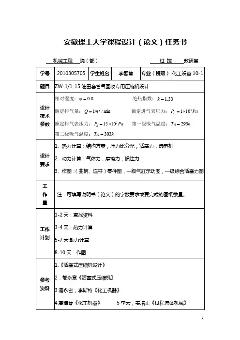
安徽理工大学课程设计(论文)任务书机械工程院(部)过控教研室目录一.计划任务书-----------------------------------------------------------------------------1 二.目录----------------------------------------------------------------------------------------2 三.概述------------------------------------------------------------33.1压缩机的应用-------------------------------------------------33.2压缩机的分类------------------------------------------------33.3压缩机的基本结构---------------------------------------------43.4活塞压缩机的工作原理-----------------------------------------4四.总体设计-----------------------------------------------54.1 设计活塞式压缩机应符合以下基本原则--------------------------54.2已知的参数和压缩机主要结构参数的选取------------------------5五.热力计算----------------------------------------------65.1计算总压力比并选择级数--------------------------------------6 5.2确定各级压力比分配------------------------------------------6 5.3确定各级容积效率--------------------------------------------65.4确定析水系数------------------------------------------------75.5.确定各级行程容积--------------------------------------------75.6.确定各级气缸直径,行程和实际行程容积------------------------75.7计算活塞力--------------------------------------------------85.7.1计算实际吸排气压力--------------------------------------95.7.2活塞力的计算 ------------------------------------------95.8确定各级的排气温度-----------------------------------------105.9.计算轴功率并选配电机---------------------------------------10 六.动力计算-----------------------------------------------------116.1已知条件和数据---------------------------------------------116.2作各级汽缸设计示功图---------------------------------------116.3作图法绘制综合活塞力图-------------------------------------126.4计算往复惯性力---------------------------------------------126.4.1第一列往复惯性力计算-----------------------------------126.4.2第二列往复惯性力计算-----------------------------------136.5摩擦力计算-------------------------------------------------156.5.1往复运动摩擦力F-------------------------------------15s f6.5.2旋转摩擦力F-----------------------------------------15fr6.6计算第I列气体力-------------------------------------------156.6.1第I级盖侧的气体力--------------------------------------156.6.2第I级轴侧的气体力--------------------------------------176.6.3计算第一列综合活塞力及切向力---------------------------186.7计算第Ⅱ列气体力-------------------------------------------196.7.1第Ⅱ级盖侧的气体力-------------------------------------196.7.2第Ⅱ级轴侧的气体力------------------------------------- 206.7.3计算第二列综合活塞力及切向力---------------------------21 七.机座部分主要零件设计---------------------------------------227.1 曲轴设计----------------------------------------------------227.1.1 曲轴设计基本原则----------------------------------------227.1.2 曲轴结构尺寸的确定--------------------------------------237.2连杆设计----------------------------------------------------237.2.1 连杆主要尺寸的确定--------------------------------------237.2.2 连杆的计算----------------------------------------------25 八.参考文献-------------------------------------------------------------------------------27三.概述3.1 压缩机的应用随着近代科学技术的不断发展,作为重要能量形式之一的压力能在工业生产上的应用已十分普遍,所占的地位相当重要。
4L-208型活塞式空气压缩机的选型及设计()摘要:随着国民经济的快速发展,压缩机已经成为众多部门中的重要通用机械。
压缩机是压缩气体提高气体压力并输送气体的机械,它广泛应用于石油化工、纺织、冶炼、仪表控制、医药、食品和冷冻等工业部门。
在化工生产中,大中型往复活塞式压缩机及离心式压缩机则成为关键设备。
本次设计的压缩机为空气压缩机,其型号为D—42/8。
该类设备属于动设备,它为对称平衡式压缩机,其目的是为生产装置和气动控制仪表提供气源,因此本设计对生产有重要的实用价值。
活塞式压缩机是空气压缩机中应用最为广泛的一种,它是利用气缸内活塞的往复运动来压缩气体的,通过能量转换使气体提高压力的主要运动部件是在缸中做往复运动的活塞,而活塞的往复运动是靠做旋转运动的曲轴带动连杆等传动部件来实现的。
关键词:活塞式压缩机;结构;设计;强度校核;选型1.1压缩机的用途4L—20/8型空气压缩机(其外观图见下页),使用压力0.1~1.6Mpa(绝压)排气量20m3 /min,可用于气动设备及工艺流程,适用于易燃易爆的场合。
该种压缩机可以大幅度提高生产率,工艺流程用压缩机是为了满足分离、合成、反应、输送等过程的需要,因而应用于各有关工业中。
因为活塞式压缩机已得到如此广泛的应用的需要,故保证其可靠的运转极为重要。
气液分离系统是为了减少或消除压缩气体中的油、水及其它冷凝液。
本机为角度式L型压缩机,其结构较紧凑,气缸配管及检修空间也比较宽阔,基础力好,切向力也较均匀,机器转速较高,整机紧凑,便于管理。
本机分成两列,其中竖直列为第一列,水平列为第二列,两列夹角为90度,共用一个曲拐,曲拐错角为0度。
1.2压缩机的工作原理和结构简介1.2.1工作原理本机为往复活塞式压缩机,依靠气缸内往复运动的活塞压缩气体容积而提高其压力。
当驱动机(电机)开启后,通过弹性联轴器带动压缩机的曲轴作旋转运动,不断旋转的曲轴使连杆不停的摆动,从而牵动十字头、活塞杆、活塞分别在十字头滑道内和气缸内作往复直线运动[5]。
单螺杆空气压缩机的结构毕业设计论文说明书摘要本设计主要阐述了单螺杆空气压缩机的工作原理与工作过程。
并详细阐述了其控制系统的设计方法及控制原理,采用了目前世界上较为先进的可编程控制器——三菱FX2N-64MS,实现空压机无人留守的自动化控制。
该PLC具有体积小、一体封装、工控能力强、可扩展等一系列优点完全可以满足生产的需要。
设计中为了满足可靠性的要求,特别设立了声光自动报警系统,及BCD码故障指示装置实现了双重保护,工作更加的安全可靠。
在其相序、缺相保护电路中引进了功能强大的相检芯片TC783A,该芯片工作可靠,可承受9—15V的电压,耐压范围广,是目前较为理想的相序、缺相检测电路用芯片。
关键词:单螺杆空压机 PLC 自动化控制 TC783AAbstractThe paper describes mainly on the design of single screw air compressor working principle and working process, and detailed design of the control system and control theory, Use of the world's more advanced programmable logic controller--MitsubishiFX2N-64MS, No one left to achieve the automation of compressor control. The PLC has a small, integrated package, industrial capacity, scalability and other advantages of full production to meet the needs of. Design in order to satisfy the requirements of reliability, in particular the establishment of a sound and light automatic alarm systems, and installation instructions BCD code failure to achieve a double protection, the more safe and reliable. In its phase sequence, and none of the protection circuit to introduce a powerful chip with Frederick TC783A, The chip is reliable and can withstand the voltage 9-15V, voltage range is the ideal sequence, missing phase detection circuit chip. Keywords: single screw air compressor PLC Automation TC783A目录摘要 (I)Abstract......................................................................................................................................................... I I 第1章绪论 .. (1)1.1 单螺杆空气压缩机的用途与市场 (1)1.2单螺杆空气压缩机优缺点 (1)1.3 单螺杆空气压缩机的结构设计 (3)1.4 PLC的发展史及发展方向 (5)1.5 PLC的结构及基本配置 (9)1.6 可编程控制器的特点 (11)1.7可编程控制器的工作原理 (12)第2章硬件设计 (14)2.1系统工作原理 (14)2.1.1系统流程及零件功能简介 (14)2.2 单螺杆空气压缩机的PLC控制系统的设计 (17)2.2.1 控制系统PLC设计原则 (17)2.2.2 PLC的选型设计 (18)2.3 FX2N-64MS的意思及其编程元件 (19)2.4 BCD的工作原理 (24)2.5 TC783A为三相相序和缺相检测电路 (28)第3章软件设计 (31)3.1软件流程图的软件设计 (31)3.2 软件流程图 (31)3.3 FX2N系列PLC编程语言及系统控制原理 (32)3.4 FX2N系列的基本逻辑指令 (37)3.5功能图编程语言 (40)3.6设计梯形图 (41)结论 (46)参考文献 (48)致谢 (49)第1章绪论1.1 单螺杆空气压缩机的用途与市场单螺杆空气压缩机主要用于石油、化工、能源、交通、机械、冶金、矿山、建筑、医药、食品等领域。
过程流体机械课程设计院系:指导老师:目录1 课程设计任务 (3)1.已知数据 (3)2.课程设计任务及要求 (4)2 热力计算 (5)1.初步确定压力比及各级名义压力 (5)2.初步计算各级排气温度 (5)3.计算各级排气系数 (6)4.计算各级凝析系数及抽加气系数 (8)5.初步计算各级气缸行程容积 (8)6.确定活塞杆直径 (9)7.计算各级气缸直径 (10)8.实际行程容积及各级名义压力 (10)9.计算缸内实际压力 (12)10.计算各级实际排气温度 (13)11.缸内最大实际气体力并核算活塞杆直径 (13)12.复算排气量 (15)13.计算功率,选取电机 (15)14.热力计算结果数据 (16)3 动力计算 (18)1.第Ⅰ级缸解析法 (18)2.第Ⅰ级缸图解法 (28)3.第Ⅱ级缸解析法 (31)4.第Ⅱ级缸图解法 (40)4 零部件设计 (44)1 课程设计任务1.已知数据1.1结构型式3L-10/8空气压缩机的结构型式为二列二级双缸双作用L型压缩机1.2工艺参数Ⅰ级名义吸气压力:P1I =0.1MPa(绝),吸气温度T1I=40℃Ⅱ级名义排气压力:P2II =0.9MPa(绝),吸入温度T2II=50℃排气量(Ⅰ级吸入状态):V d =10 m3/min 空气相对湿度: φ=0.81.3结构参数活塞行程: S=2r=200mm电机转速: n=450r/min活塞杆直径: d=35mm气缸直径:Ⅰ级,DI =300mm ;Ⅱ级,DII=180mm ;相对余隙容积:α1=0.095,αII=0.098;电动机:JR115-6型,75KW;电动机与压缩机的联接:三角带传动;连杆长度:l=400mm;运动部件质量(kg):见表2-1表2-1 运动部件质量2.课程设计任务及要求a. 热力计算:包括压力比分配,气缸直径,排气量,功率,各级排气温度,缸内实际压力等。
b.动力计算:作运动规律曲线图,计算气体力,惯性力,摩擦力,活塞力,切向力,法向力,作切向力图,求飞轮矩,分析动力平衡性能。
一摘要 (3)一、前言 (4)二、空气压缩机结构组成 (5)1、冷却与润滑系统 (5)2、分离系统 (6)3、控制与安全保护系统 (6)4、微电脑操作系统 (7)三、压缩机的分类 (9)3.1、喷油螺杆空气压缩机 (9)3.2、喷油螺杆制冷压缩机 (9)3.3、喷油螺杆工艺压缩机 (10)3.4、干式螺杆压缩机 (10)3.5、喷水螺杆压缩机 (10)3.6、其他机械 (11)四、压缩机的特点 (11)五、空压机的原理与控制 (12)5.1、螺杆空气压缩机工作原理: (13)5.2、空气压缩机的电器控制部分: (13)六、空气压缩机的工作过程 (14)6.1、吸气阶段 (15)6.2、压缩阶段 (15)6.3、排气阶段 (15)七、双螺杆空压机的工作流程 (15)八、空气压缩机的维护与保养 (17)8.1、油管路 (18)8.2、油过滤器 (18)8.3、油气分离器滤芯 (18)8.4、冷却润滑油 (18)8.5、保护性停机系统 (19)8.6、空气滤清器滤芯 (19)8.7、油冷却器、后冷却器: (20)8.8、带轮部件 (20)8.9、电气线路 (21)九、故障诊断及应急处理 (21)9.1进行任何维护前必须切断主电源。
(22)十、设备的安装方法 (25)10.1、安装新风包: (26)10.2、安装风机底盘: (26)10.3、安装风机本体: (26)10.4、寸管路。
(26)10.5、制作安装出风管路: (26)10.6、安装启动器与断路器 (26)10.7、安装高低压线路: (27)10.8、安装微机保护装置 (27)10.9、安装微机保护电源线 (27)10.10、安装控制线路: (27)十一、煤矿井下空气压缩机检查一览表检查类型 (27)十二、关于井下使用移动式空气压缩机的安全措施 (28)十三、经济与社会效益分析 (30)十四、节能经济分析 (31)14.1 运用节能型主机 (31)14.2 卓越的主机设计 (31)14.3 高效的节能控制系统 (31)14.4 Intellisys 智能控制器全权掌握压缩空气的排气量 (32)14.5 适合在高温环境下运行3 (32)14.6 振动噪音小 (32)14.7 润滑油使用寿命长 (32)14.8 使用高效电机 (32)14.9 真空接触器替代真空断路器 (33)十五、压缩机的发展方向 (34)十六、结论 (35)十七、致谢 (36)十八、参考文献 (37)一摘要空气压缩机是喷油单级双螺杆压缩机,分为单空气压缩机及双空气压缩机,采用高效带轮传动,带动主机转动进行空气压缩,通过喷油对主机内的压缩空气进行冷却,主机排出的空气和油混合气体经过粗、精两道分离,将压缩空气中的油分离出来,最后得到洁净的压缩空气。
ZW 500D 无油低噪音空气压缩机说明书前言:一、多谢阁下赏识。
此机能提供稳定的无油气源。
避免油渍进入人体,影响粘固质量和工作环境,又能避免终端机器的非耐油管因有油和气压过高引发故障。
二、需水平安放在室内干燥、清洁、通风场所,特别注意远离粉尘之类的范围,如无法达到要求,必须增加过滤。
三、此机组额定电压110±5%V AC60Hz500W 5.0A,电流所经过的电源线、保护装置等必须接触良好和能承受电动机起动时约10安培的电流。
四、每季度清洁过滤器海绵的粉尘一次,每月查看电磁阀是否正常排空和每星期排水一次,排水方法:打开底部排水堵头,污水由排污口排出。
五、机组编号在500A 后面有七位数,前二位是生产年份、第三位是月份(按英文字母顺序排列)、最后四位数是当月生产第几台的序号。
如无购机凭证,保修期以出厂编号日期算起,一年内为保修期。
试机:插上电源插座,机组运行,关闭各气开关,充气至8.0bar 时自动关机并自动排空,静听无漏气现象,放气至4.0bar 时机组自动开机充气至8.0bar 自动停机 ,拉出插头,移致固定处水平放好,接好气管,插好插头,机组充满气停机,打开供气开关,观察压力表应无降压,确认终端机器无漏气现象,即可投入使用。
电路图:气路解剖侧面图:机组工作时,空气由进气消声过滤器进入泵头,经泵头压缩为高压,由铜管流到气罐,再由气罐流到单向阀,因机组通电工作,电磁阀线圈通电,把电磁阀芯吸上,封闭电磁阀的常开气孔,高压只有经单向阀充入储气罐。
当储气罐的压力达到8.0bar 时,气控开关自动跳开,切断电源,泵头停机、电磁阀失去磁吸,阀芯被弹簧弹出,打开常开孔,把铜管、气罐和泵头的高压排泄到空气中,而储气罐内的高压因单向阀反向不通而储存气源,放气开关输出。
(压力表的压力指示是储气罐内的气体压力)。
维修:1、机组保修一年,半年内因质量问题可换免费维修(如雷击、电压超高、进水、泵头吸入沙粉错成气压打不起、人为等现象除外)。
ψX90Λ-4空气压缩机使用说明书编号:2009056 目录:1.YC90L-4型空气压缩机主要技术规范2.压缩机主要部件简述3.压缩机的安装要求4.压缩机的试运转5.压缩机的正常操作6.压缩机可能发生的故障及消除7.压缩机的检修8.压缩机的启封9. 附录A :机体与电机的安装1.ZW-22.5/8型空气压缩机主要技术规范(1)型式:立式、两列、二级、双作用、水冷、气缸无润滑(2)输气量1350m 3/h±5%(吸入状态)(3)吸入介质状态:大气吸入进气压力:当地大气压 进气温度:≤35℃(4)最终压力:0.8MPa (G ) (5)末级冷却器后出气温度:≤40℃(6)气缸直径:一级缸φ430mm ,二级缸φ250mm(7)活塞行程:180mm(8)转速:590r/min(9)曲轴旋转方向:从油泵端看为逆时针方向(10)传动方式:皮带轮传动(11)轴功率:132kW(12)压缩机总重量:~6000kg(包括电动机、辅机、管道)(13)电动机:型号Y315M-4电压 380V转速 1485r/min功率 132kW(14)冷却水压:进水压力 0.3Mpa(G);回水压力 0.25Mpa (G)(15)冷却水进水温度:〈30℃(16)却水耗量:~15T/h(17)一级进气管径:φ219×6(18)末级出气管径:φ133×42.压缩机主要部件简述本机主要由机身、曲轴、连杆、十字头、刮油器、油过滤器、油冷却器、机带油泵、动力装置、气缸、活塞、气阀、密封器、高效气体冷却器、管路系统以及压缩机控制柜等部件组成。
气体的压缩过程见随机图纸Y201.LC流程图。
2.1 机身压缩机的机身是包括曲轴箱、中间体铸成的整体,其材质为高强度铸铁铸成。
曲轴用稀土球墨铸铁铸成,支承在曲轴箱中的两个轴承上,两列曲拐相差 180度。
曲轴一端的飞轮通过皮带与电动机联接,另一端通过超越离合器带动齿轮油泵。
课程名称:
设计题目:
班级:专业:
学生姓名:学号:
指导教师(签字):
起止日期:年月日—年月日
基本要求及注意事项
1.说明书的编写内容及格式参看课程设计指导书的有关部分.
2.为说明清楚,应有必要的插图(如传动方案,电路图、结构简
图以及统计分析图等)。
3.除插图可以用铅笔绘制外,计算与说明一律用钢笔书写,并要
求计算正确、完整,文字简明扼要,书写简洁。
4.设计过程中所引用的计算公式和数据,应注明来源(参考资料
的代号,页次以及图表编号等),以便老师审查。
5.根据计算稿本整理设计主要过程时,只须首先列出文字符号表
达的计算公式。
并依次代入各相应文字符号的数值后,就直接写出计算结果(不作任何运算和简化,但结果必须注明单位)。
6.有些课程(如机械设计等)需在说明书右侧分出主要结果栏,
将设计中所选主要参数,尺寸或规格以及主要计算结果等,均应写入右侧结果栏中(但无须将所有数据或数值都列入此栏);
有的也可采用表格形式列出。
7.对主要计算结果应有简短的结论,如计算结果与实际取值相差
较大时应做简短的解释,并说明其原因。
8.对每一自成单元的内容,都应有大小标题和前后一致的顺序编
号,使其醒目突出。