空气压缩机ZB-0.1产品说明书
- 格式:pdf
- 大小:1.08 MB
- 文档页数:11
空气压缩机操作说明操作说明:空气压缩机一、引言空气压缩机是一种常见的工业设备,广泛应用于各个行业。
本操作说明旨在提供给用户清晰的操作步骤,帮助用户正确、安全地使用空气压缩机。
二、安全注意事项在操作空气压缩机之前,请务必遵循以下安全注意事项:1. 在操作前,确保您已经阅读并理解了使用说明书,并了解设备主要部件的名称和功能。
2. 操作空气压缩机时,请穿戴合适的个人防护设备,如安全手套、护目镜和防护服。
3. 在操作前,确保空气压缩机已正确接地,并检查电源电压是否与设备额定电压匹配。
4. 在操作过程中,严禁触摸旋转部件,如皮带,以免伤及身体。
5. 使用空气压缩机时,请确保操作环境通风良好,并避免操作在潮湿或易燃易爆的场所。
6. 如果在操作过程中发现任何异常现象,请立即停止使用,并及时联系售后服务部门。
三、操作步骤1. 打开电源开关,并确保电源指示灯点亮。
2. 按照空气压缩机的起动顺序,打开冷却水阀门,确保水源充足。
3. 打开油液进气阀门,并观察油液压力表,确保油液压力正常。
4. 将空气压缩机的工作方式调至手动模式,并打开气体启动阀。
5. 根据所需的气体压力,调节气体输出压力表,确保压力在设定范围内。
6. 根据操作需要,调节空气压缩机的工作时间和停机时间,并确保定时器功能正常。
7. 在操作结束后,首先关闭气体启动阀,再关闭油液进气阀门。
8. 关闭冷却水阀门,并确认油液压力表显示正常。
9. 最后,关闭空气压缩机的电源开关。
四、维护保养正确的维护保养可延长空气压缩机的使用寿命和性能稳定性。
以下是常见的维护保养事项:1. 定期检查油液的质量和油位,确保油液清洁且充足。
2. 清洁和更换油液过滤器,防止灰尘和杂质对设备产生不良影响。
3. 定期检查和紧固连接螺丝,以防止部件松动引起的故障。
4. 清洁冷却系统和散热器,保证散热良好。
5. 定期检查电源电压和电气部分的连接情况,确保设备正常工作。
6. 定期清洁设备表面,保持设备整洁。
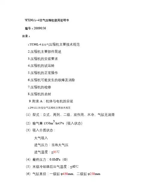
ψX90Λ-4空气压缩机使用说明书编号:2009056 目录:1.YC90L-4型空气压缩机主要技术规范2.压缩机主要部件简述3.压缩机的安装要求4.压缩机的试运转5.压缩机的正常操作6.压缩机可能发生的故障及消除7.压缩机的检修8.压缩机的启封9. 附录A :机体与电机的安装1.ZW-22.5/8型空气压缩机主要技术规范(1)型式:立式、两列、二级、双作用、水冷、气缸无润滑(2)输气量1350m 3/h±5%(吸入状态)(3)吸入介质状态:大气吸入进气压力:当地大气压 进气温度:≤35℃(4)最终压力:0.8MPa (G ) (5)末级冷却器后出气温度:≤40℃(6)气缸直径:一级缸φ430mm ,二级缸φ250mm(7)活塞行程:180mm(8)转速:590r/min(9)曲轴旋转方向:从油泵端看为逆时针方向(10)传动方式:皮带轮传动(11)轴功率:132kW(12)压缩机总重量:~6000kg(包括电动机、辅机、管道)(13)电动机:型号Y315M-4电压 380V转速 1485r/min功率 132kW(14)冷却水压:进水压力 0.3Mpa(G);回水压力 0.25Mpa (G)(15)冷却水进水温度:〈30℃(16)却水耗量:~15T/h(17)一级进气管径:φ219×6(18)末级出气管径:φ133×42.压缩机主要部件简述本机主要由机身、曲轴、连杆、十字头、刮油器、油过滤器、油冷却器、机带油泵、动力装置、气缸、活塞、气阀、密封器、高效气体冷却器、管路系统以及压缩机控制柜等部件组成。
气体的压缩过程见随机图纸Y201.LC流程图。
2.1 机身压缩机的机身是包括曲轴箱、中间体铸成的整体,其材质为高强度铸铁铸成。
曲轴用稀土球墨铸铁铸成,支承在曲轴箱中的两个轴承上,两列曲拐相差 180度。
曲轴一端的飞轮通过皮带与电动机联接,另一端通过超越离合器带动齿轮油泵。
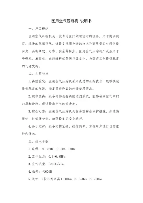
医用空气压缩机说明书一、产品概述医用空气压缩机是一款专为医疗领域设计的设备,用于提供稳定、纯净的压缩空气。
该设备采用先进的技术和高质量的材料制造而成,具有高效、可靠、安全等特点。
医用空气压缩机广泛应用于呼吸机、麻醉机、血液透析仪等医疗设备中,为医疗工作提供稳定的气源支持。
二、主要特点1.高效稳定:医用空气压缩机采用先进的压缩技术,能够快速提供稳定的气流,满足医疗设备的连续使用需求。
2.纯净度高:设备内部设有高效过滤系统,能够去除空气中的杂质和微粒,保证输出空气的纯净度。
3.安全可靠:医用空气压缩机具有多重安全保护措施,如过热保护、过载保护等,确保设备的安全运行。
4.易于维护:设备结构紧凑、操作简单,方便用户进行日常维护和保养。
三、技术参数1.电源:AC 220V ± 10%,50Hz2.工作压力:0.6-0.8MPa3.空气流量:≥30L/min4.噪音:≤60dB5.尺寸:(长×宽×高)500mm × 350mm × 700mm6.重量:约50kg四、使用方法1.安装:将医用空气压缩机放置在平整、通风的地方,确保设备与周围物体保持一定距离,便于散热和维护。
2.连接:使用专用管道将医用空气压缩机的输出端口与医疗设备的进气端口连接起来,确保连接牢固、密封。
3.开机:插上电源插头,打开电源开关,设备即进入待机状态。
按下启动按钮,设备开始工作,输出压缩空气。
4.调节:根据医疗设备的需求,调节医用空气压缩机的输出压力和流量。
5.关机:按下停止按钮,设备停止工作。
断开电源开关,拔掉电源插头。
五、注意事项1.安全用电:请使用符合规格的电源插座和电源线,避免过载和短路。
2.定期维护:定期对医用空气压缩机进行清洁和保养,检查设备内部零件是否松动或损坏,及时更换损坏的零件。
3.使用环境:避免在高温、潮湿或灰尘较多的环境中使用设备,以免影响其性能和寿命。
4.故障排除:如设备出现故障或异常情况,请立即停止使用,并及时联系专业维修人员进行检查和维修。
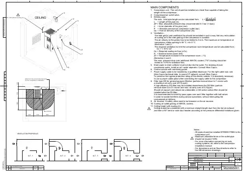
EdPosi-tionModified fromDateIntr./Appd.123456789A10BCDEFGParent 3D modelEd . Version 3DC O N F IDE N T I A L :T h i s d o c u m e n t i s o u r p r o p e r t y a n d s h a l l n o t w i t h o u t o u r p u r p e r m i s s i o n b e a l t e r e d ,c o p i e d , u s e d f o r m a n u f a c t u r i n g o r c o m m u n i c a t e d t o a n y o t h e r p e r s o n o r c o m p a n y03Ceiling height & Note added2013-04-08 982069500101.00 P x d x P450 x Qc51.85MAIN COMPONENTS1. Compressor unit : The unit should be installed on a level floor capable of taking the weight of the compressor.2. Compressed air outlet valve.3. Delivery pipe : The max . total pipe length can be calculated from L = L = Length of the pipe (m)P = Max. allowable pressure drop (recommended 0.1 bar (1.5psi)) d = Inner diameter of the pipe (mm)P = Absolute pressure at compressor outlet (bar) Qc = Free air delivery of the compressor (l/s)4. Ventilation :The inlet grid(s) and ventilation fan should be installed in such a way that any recirculation of cooling air to the inlet grating of the compressor is avoided.The air velocity to the grid(s) has to be limited to 5 m/s. The maximum air temperature at compressor intake opening is 46 C, min 0 C. Alternative 1 and 3 :The required ventilation to limit the compressor room temperature can be calculated from : Qv = 1.19 N / TQv = Required cooling air flow (m /s) N = Nominal motor power (kW)T = Temperature increase in the compressor room. ( C) Alternative 2 and 4 :The max. pressure drop over additional AIR/OIL coolers ("10") ducting should be limited to 10 Pa for standard fans.5. Drain pipes to drain collector must not dip into the water. For draining of pure condensate water, install an oil / water seperator. Consult Atlas Copco.6. Control cubicle with monitoring panel.7. Power supply cable to be installed by a qualified electrician. For the right cable size, see Atlas Copco technical data. In case of IT network, consult Atlas Copco.To preserve the ingress protection rating of the electric cubicle, it is absolutely necessary to use a proper cable gland when connecting the supply cable to the compressor.8. Filter type DD for general purpose filtration (particle removal down to 1 micron with a maximum oil carry over of 0.5 ppm).A high efficiency PD filter may be installed downstream the DD filter (particle removal down to 0.01 micron and max. oil carry over of 0.01ppm)Should oil vapours and odours be undesirable, a QD active carbon filter should be installed after the PD filter.It is recommended to install by-pass pipes over each filter together with ball valves in order to isolate the filters during service operations, without interrupting the compressed air delivery.9. Air receiver: A safety valve need to be foreseen on the air receiver.10. Cooling air outlet grating of AIR/OIL coolers.11. Ceiling height with ducting (h);Ceiling should be considered with a minimum straight length duct from the hot air exhaustand then a 90 bend or main duct header according to the pressure differential limitations given.Fini wt.Approved.TreatmentMaterial Name Drawn byDes checked.Scale Blank wt .Prod checked.FamilyBlank nr.KgDesignation SheetINVReplacesCompare DateDrawing owner/Confidentiality Class STATUSTolerances, if not indicated, according to:A1Not Applicable 1114/03/200598206950010N/AInternalNot ApplicableApproved InternaldavinciAPIacc. to 1102 KDIMENS. INSTALL.Drawing format Notes :- All pipes should be installed STRESS FREE to the compressor unit.- Maximum allowable force on the outlet pipe should not exceed 100N.- For more information concerning air nets, cooling systems, etc refer to the compressor installation manual.- For dimensions and air flow directions refer to the AIB dimension drawings.VENTILATION PROPOSALSALT. 1ALT. 2ALT. 3ALT. 42345678800500800200610630Minimum free area to be reserved for the compressor installationControllerA l l m a t e r i a l s s u p p l i e d a r e i n c o m p l i a n c e w i t h t h e r e q u i r e m e n t s o f t h e L i s t o f P r o h i b i t e d S u b s t a n c e s333Min. 800 without ducting (h)CEILINGATLAS COPCO STANDARD CLASS -/-。
无油静音空气压缩机Oil Free Air Compressor使用说明书InstructionsISO9001:2000上海岱洛工贸有限公司注意:在安装调试,操作使用或保养维护本机前,请务必详阅此说明书!特别提醒:1.本产品为无油空气压缩机,用户切勿添加任何润滑油!2.请定期排净储气罐和过滤减压阀水杯中的水分,建议3天左右排一次!非常感谢您选择使用本公司生产的DYNAIR大圣牌无油低噪音空压机!它是本公司采用美国先进压缩机技术精心研制的多用途节能型机电一体化产品。
真正具有噪音低,体积小,造型美观,耗电省,维护简单以及安全耐用等优点。
可广泛使用于医疗器械,分析仪器,教学科研,国防,环保,轻工,食品加工,制药机械,日常生活等领域,是各种器械配套的理想气源,是性能优良的进口替代产品。
一、安全须知以下所列出的是使用大圣牌医用无油空气压缩机时需遵守的的安全注意事项。
使用前请仔细通读,阅读后妥善保存。
使用时必须绝对遵守安全事项,以防火灾、触电、人身伤害及其它事故。
1、保持工作场所清洁:杂乱无章容易导致事故发生。
2、注意工作场所环境:空压机不可任其风吹雨打,勿在潮湿和阴暗的地方工作,勿在存放易燃易爆液体气体和多灰尘的地方工作。
3、谨防触电:在使用空压机时,请不要让身体触及接地物品(如导管、暖气管、电冰箱等)。
4、外人/孩童勿近:不让孩童与作业无关的人员靠近空压机,以孩伤害、触电。
5、妥善保管机器:不使用的空压机,应放掉储气罐内的空气与污水,存放于干燥的环境中。
6、勿强迫使用机器:按照空压机上的标定的电压、速率或负载操作,效果会更佳更安全。
(连续运转时间不超过一小时,否则会影响使用寿命)7、保护电缆:不得扯拉电缆从电源拔出插头,电缆应远离热源和油液,并避免与锐利的物体接触。
8、妥善保养机器:应根据使用情况及时清洗滤清器,定期检查附件、电缆线,损坏立即更换。
应保持机器清洁干爽不沾油污,这样才能充分发挥性能。
9、及时切断电源:下班不使用时,养成及时切断电源的习惯。
气动压缩机使用说明书尊敬的用户:感谢您选购本公司的气动压缩机,并选择阅读本使用说明书。
本说明书旨在为您提供详细的操作指导,确保您能正确、安全地使用气动压缩机,延长其使用寿命,并保证使用过程中没有任何问题。
一、产品概述气动压缩机是一种能将空气压缩为高压气体的装置。
它采用了先进的气动技术和优质材料,具有高效、稳定的特点,并广泛应用于工业生产、建筑施工等领域。
本款气动压缩机不仅具备出色的性能,还具有节能环保的特点。
二、安全须知1. 在使用之前,请您阅读本说明书,并严格遵守其中的操作指南。
2. 在操作过程中,请确保设备处于平稳的工作环境,并确保设备周围没有任何障碍物。
3. 请勿擅自改动设备的任何部件,以免引起故障或危险。
4. 在开机之前,请检查供电电压是否与设备标识的电压相符;确保电源线路连接牢固可靠。
5. 贵重物品请保持远离设备工作区域,以防意外损坏。
6. 在设备运行时,严禁触摸设备表面和内部零部件,以免导致烫伤或电击。
7. 在操作过程中,如发现任何异常现象,请立即停止使用设备,并与售后服务中心联系。
三、操作方法1. 确保设备已连接到稳定的电源,并打开电源开关。
2. 打开设备侧面的压力调节阀,根据需要调整压力大小。
3. 检查油箱内的润滑油是否充足,必要时添加合适的润滑油。
4. 打开气动压缩机的控制开关,让设备开始运行。
5. 在设备运行过程中,注意观察压力表的读数,确保压力在安全范围内。
6. 使用完毕后,先关闭气动压缩机的控制开关,再关闭电源开关。
7. 断开电源连接前,请务必确认设备已完全停止运行。
四、设备保养1. 定期清洁设备表面,以保持设备清洁整洁的外观。
2. 按照说明书中的要求更换润滑油,以保证设备内部的正常运转。
3. 定期检查设备的连接部件是否松动,必要时做紧固处理。
4. 如发现设备有任何故障或异常情况,请及时联系售后服务中心进行检修和维护。
五、常见故障与排除方法以下列举了一些常见故障及其排除方法,供您参考:1. 故障一:设备无法启动- 排除方法:检查电源连接是否松动,确认电源是否正常供电。
小型真空单元真空发生器/真空泵系统ZB系列安全注意事项 2 型号表示・型号体系9 产品各部分名称12 安装・设置13 空气源15 使用供给压力16 配管16 V通口Ass’y品的使用17 关于电磁阀21 构造图・零件构成25 维护・保养26 滤芯更换要领28 吸音材更换要领28 电磁阀(供给阀・破坏阀)更换要领29 关于集装式产品30 关于过滤罩30 关于破坏流量调整针阀31 关于真空发生器的排气31 规格32 回路图35 重量37 真空发生器的排气特性・流量特性38 真空泵系统流量特性39 关于流量特性表40 关于压力传感器Ass’y品40 关于真空用压力开关Ass’y品41 故障一览表42此处所示的注意事项是为了能安全正确的使用本产品,预先防止对您和他人造成危害或损失而定。
为了表示这些事项的危险程度,将注意事项分成「注意」「警告」和「危险」三个等级。
不论哪个等级,都是与安全相关的重要内容,除了必须遵守国际规格(ISO/IEC)、日本工业规格(JIS)※1)以及其他安全规则※2以外,这些内容也请务必遵守。
*1) ISO 4414: Pneumatic fluid power -- General rules relating to systems.ISO 4413: Hydraulic fluid power -- General rules relating to systems.IEC 60204-1: Safety of machinery --Electrical equipment of machines. (Part1: General requirements)ISO 10218-1992: Manipulating industrial robots -Safety.JIS B 8370: 空气压系统通则JIS B 8361: 油压系统通则JIS B 9960-1: 机械类的安全性-机械的电气装置((第1部:一般要求事项)JIS B 8433-1993: 键控工业机器人-安全性等*2) 劳动安全卫生法等注意: 误使用时,有可能对人和物品造成损害。
空压机说明书空压机说明书工作原理:皮带传动式单级压缩机的工作原理是,电机通过三角带驱动压缩机主机皮带轮带动曲轴,使活塞在气缸内作往复运动压缩空气,引起气缸容积变化。
在压缩行程中,气缸容积缩小,气缸内的空气压缩到额定排气压力后,通过排气阀的作用,经过排气管、单向阀进入储气罐。
皮带传动式两级压缩机的工作原理是,一级压缩空气通过连接管再进入另一只气缸,将气缸内空气压缩到额定排气压力后,通过排气阀的作用,经过排气管、单向阀进入储气罐。
压缩机装有自动压力开关控制电机,当储气罐的空气压力达到所调整的排气压力时,空压机自动停机。
当储气罐的空气压力降低到一定范围内时,压缩机会重新启动,从而使储气罐里的压缩空气的压力保持在一定的范围内,达到自动控制的目的。
安装及准备:1.使用本机前需检查机头、皮带轮螺丝及各部件螺丝是否松动,并锁紧。
2.使用本机前,务必详细阅读本机使用说明书。
3.空压机必须放置于清洁、干燥、通风的地方。
皮带轮传动方向的一侧靠墙或其它物品时,最小距离应大于30cm以上,环境温度-20℃-40℃为宜。
4.启动前必须检查空压机油量是否足够,标准油位应在油镜中红圈(或红线)的中线位置,油位不得过高或过低。
5.外接电源时请参照本说明书中的空压机外接电源配线标准配电源线。
在接线前,务必按空压机出厂时的引出线连接,禁止使用非压缩机所配电机接线盒,内外接电源。
6.确认电源电压及频率是否符合本机产品合格证所规定的电压及频率,安装空压机时,必须安装塑料外壳式断路器(空气开关),禁止使用闸刀控制空压机。
7.确认所购空压机是否符合您所需要的额定排气量和额定排气压力。
使用、维护和保养:1.使用前应检查压缩机皮带轮转动方向,是否符合压缩机防护罩所粘贴的箭头方向。
2.启动或停止空压机必须用压力开关控制,拔起压力开关的圆钮,空压机即启动;反之,空压机即停止。
3.在使用过程中,若发现空压机有异常情况,应立即切断总电源,待事故排除后,方可重新启动。
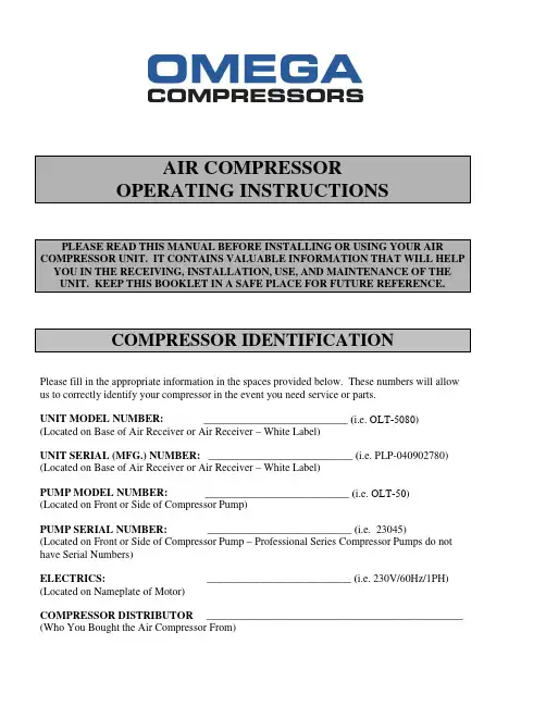
AIR COMPRESSOROPERATING INSTRUCTIONSPLEASE READ THIS MANUAL BEFORE INSTALLING OR USING YOUR AIR COMPRESSOR UNIT. IT CONTAINS VALUABLE INFORMATION THAT WILL HELP YOU IN THE RECEIVING, INSTALLATION, USE, AND MAINTENANCE OF THE UNIT. KEEP THIS BOOKLET IN A SAFE PLACE FOR FUTURE REFERENCE.COMPRESSOR IDENTIFICATIONPlease fill in the appropriate information in the spaces provided below. These numbers will allow us to correctly identify your compressor in the event you need service or parts.UNIT MODEL NUMBER: ___________________________ (i.e. OLT-5080) (Located on Base of Air Receiver or Air Receiver – White Label)UNIT SERIAL (MFG.) NUMBER: ___________________________ (i.e. PLP-040902780) (Located on Base of Air Receiver or Air Receiver – White Label)PUMP MODEL NUMBER: ___________________________ (i.e. OLT-50) (Located on Front or Side of Compressor Pump)PUMP SERIAL NUMBER: ___________________________ (i.e. 23045) (Located on Front or Side of Compressor Pump – Professional Series Compressor Pumps do not have Serial Numbers)ELECTRICS: ___________________________ (i.e. 230V/60Hz/1PH) (Located on Nameplate of Motor)COMPRESSOR DISTRIBUTOR ________________________________________________ (Who You Bought the Air Compressor From)TABLE OF CONTENTS•COMPRESSOR IDENTIFICATION……………………………...………Front Cover •TABLE OF CONTENTS...............................................................................Inside Front Cover •SAFETY PRECAUTIONS……………………...………………….………pg. 1-2•GENERAL DESCRIPTION OF AIR COMPRESSOR.………...……….pg. 2•INSPECTION OF AIR COMPRESSOR……...………………...………...pg. 2•GENERAL REQUIREMENTS……………………...…………………….pg. 3•INSTALLATION – MECHANICAL……………………...………………pg. 3•INSTALLATION – ELECTRICAL………………………...……………..pg. 3-4•INITIAL START–UP PROCEDURES.............…………...……………...pg. 4-5•PREVENTATIVE MAINTENANCE……………………...……………...pg. 5•TROUBLESHOOTING………………………………...….………………pg. 6-7•WARRANTY…………………………………………...…..………………Back CoverSAFETY PRECAUTIONSPlease familiarize yourself with the following information for preventing damage to your air compressor unit and injury to the operator and/or property damage.ELECTRICAL HAZARDNever use the air compressor without connection to a properly grounded outlet with the specified voltage and fuse protection. Do not use the compressor in a wet or explosive environment, as the electrical components on the compressor are general purpose and the motors are open drip proof. The compressor must be located a minimum of 20 feet (6.1 metres) from any source of potentially explosive vapours. Never attempt maintenance or adjustment with power connected or while the equipment is in operation.TANK SAFETY VALVEThe safety valve is factory installed to prevent the air receiver from damage should malfunction occur in the pressure switch. It is factory set at a specific limit for your particular model, and should never be tampered with. Adjustment by user will automatically void warranty.PRESSURE SWITCHThe air compressor switch is set at the factory for optimum performance of your particular model. Never bypass or remove this switch as serious damage to equipment or personal injury could result from too high of pressure.MOTOR AND COMPRESSOR PUMPAir compressors become hot while in operation. Never touch the motor, compressor pump, and/or discharge tubing while in operation or immediately after operation. Touching these areas may cause severe burns. The compressor automatically operates while the power is on. Do not come into contact with moving parts. Shut off all power to the unit before attempting to repair or maintain the compressor. Never operate the compressor with the belt guard removed.COMPRESSED AIR CAUTIONCompressed air from the unit may contain poisonous vapours which are not suitable for inhaling and could be harmful to your health. Never directly inhale compressed air produced by the compressor. Always use proper filtration, carbon monoxide monitor and quality tested air for breathing applications from a compressor. Ensure your breathing apparatus meets NIOSH and OSHA requirements. Always wear proper safety equipment while using compressed air.AIR RECEIVEROver pressurizing the air receiver could cause an explosion or rupture. To protect from over pressurizing a factory preset safety valve is included. Do not remove, make adjustments or substitutions for this valve. Occasionally pull the ring on the valve to make sure that the valve operates freely. If the valve does not operate freely, it must be replaced.Never weld to, drill, or change the air receiver in any way. If any of the above conditions are changed or tampered with this may result in voiding of the manufacturer’s warranty.GENERAL DESCRIPTION OF AIR COMPRESSORTo compress air, the piston moves up and down in the cylinder. During the downstroke, air is drawn in through the inlet valve. The discharge valve remains closed. During the upstroke of the piston, air is compressed. The inlet valve closes and compressed air is forced out through the discharge valve, through the discharge tube, through the check valve and into the air receiver. Working air is not available until the compressor has raised the air receiver pressure above the requirement at the air service connection. The air inlet filter openings must be kept clear of obstructions.INSPECTION OF AIR COMPRESSOREach Omega Air Compressor is factory tested and inspected before shipment. Every attempt is made to ensure safe and complete shipment of our products. Freight damage or misplacement of goods may occur. Shipments of Omega products are the property of the consignee when the products leave our facility. Omega Compressors is not responsible for any damages or shortages caused to the products after it has left our facility.It is the responsibility of the receiver of the goods to ensure the product has been received in full and has arrived in suitable condition. Damage may not be visible at the time of off-loading, but may only become apparent upon unpacking or start-up.Should there be shortages or damages in shipment to the product, A Loss or Damage Claim should be submitted to the carrier and supported by copies of the bill of lading, invoice, estimate to repair and a damage report. Do not discard any of the products or packaging as they may be required by the carrier for inspection.GENERAL REQUIREMENTSAs the owner of a new Omega Air Compressor Unit, it is your responsibility to ensure it is installed correctly, as well as maintained and serviced on a regular basis. Information has been included in this booklet outlining the suggested air compressor maintenance schedules and a trouble shooting guide. It is important that you read this information and keep it in a safe place for future reference.INSTALLATION - MECHANICALLocate the air compressor in a clean, dry and well ventilated area. The air compressor should be located 12 to 18 inches away from walls or any other obstruction that would interfere with the air flow through the pump flywheel. If possible, the air compressor should be located in a separate room or area with an air intake or fan positioned on an outside wall for maximum air flow and cooling. The air compressor is designed with heat dissipation fins that allow for proper cooling. Keep the fins and other components clean. A clean compressor runs cooler and provides longer service. Allow room for easy access to the air compressor for maintenance and service work.For permanent installation, the compressor may be bolted to the floor through holes provided in the compressor feet. Shims and vibration isolators or vibration pads must be used to level the compressor before bolting it to the floor. Severe vibration will result when the compressor is bolted down tightly and the feet are not level. This can lead to welds cracking or fatigue failure of the air receiver.Omega Compressors offers vibration isolators or vibration pads, flex hoses, electronic auto drains or pneumatic auto drains along with a host of other accessories such as filters and refrigerated air dryers etc. to provide reliable clean dry compressed air. Ask your local Omega distributor for details on all our accessories.INSTALLATION - ELECTRICALIt is your responsibility to ensure that the Air Compressor Unit is electrically connected in a safe and correct manner. Any electrical work should be carried out by a competent electrician and installed in a way which meets all applicable codes and regulations. A magnetic starter must be an integral part of the air compressor except on contractor and professional series units. A magnetic starter may be supplied with your unit from the factory.Failure to connect the air compressor correctly to your buildings electrical services may result in serious personal injury or damage to the equipment.Please note that under normal conditions, the air compressor will operate intermittently. Should it be necessary to service the air compressor ensure the power source has been shut down. This must be done to prevent personal injury or damage to the unit.Do not attempt to operate the air compressor unit without first checking the oil level in the pump. Add oil as required. Serious damage may result from use without oil.MOTORSWiring must be done in a manner that full voltage nameplate +/- 10% is available at the motor terminals during startup. Use of an incorrect electric motor for your particular building service will result in premature motor failure and is not covered by Omega Compressors or Motor manufacturer’s warranty. The warranty that exists on the electric motor is that of the original manufacturer. In the event of a motor failure contact your Omega Distributor or Service Centre for the location of the nearest authorized motor service centre.PRESSURE SWITCHESThe pressure switch located on the compressor unit acts as a pilot device activating the coil on the magnetic starter except on contractor and professional units where the pressure switch would act as a pilot device activating the motor. The pressure switch cut in/cut out has been preset at the factory. Do not tamper with the settings. Consult your local distributor or service centre should the switch not be operating properly.PUMP ROTATIONThe compressor is to be wired in a manner that the rotation of the flywheel causes the air to be blown over the pump. This allows the pump to cool properly. When facing the nameplate side of the unit the flywheel must rotate clockwise unless otherwise noted on the unit with an arrow on the belt guard or motor.INITIAL START-UP PROCEDURE1.)Check to see that nuts and bolts are all snug. This must be done, as somefasteners may become loose in transit.2.)Check to see if the belt is installed properly, with proper tension.3.)Check belt tightness so that when pressure is applied at the centre, there is ½”slack.4.)Check that compressor is fixed on a strong, stable level base.5.)Check that air filter is clean.6.)Do not place any materials on or against the belt guard, or the compressor unititself. Placing materials there will limit the cooling of the compressor and could lead to premature failure.7.)Turn the compressor “on” momentarily by positioning the fused disconnect inthe “on” position. Ensure that the flywheel is turning in the correct position.See “PUMP ROTATION” (page 4). On compressors with three phase power, adjust the wiring at the motor terminals if the rotation is incorrect. Refer to the wiring diagram on or in the motor terminal box.8.)Open the air receiver outlet ball valve and start the unit. Ensure air is escapingto atmosphere. After running the compressor unit for twenty minutes, close the ball valve, and allow the unit to reach maximum operating pressure. Ensure that the compressor shuts down at the pre-set maximum pressure, and the headpressure is released through either the pressure switch or the CPR on the front of the pump.9.)Check the air compressor and piping systems for air leaks, and correct asrequired.10.)Shut off all power to the air compressor before attempting any repair ormaintenance.11.)Your compressor is ready for use.PREVENTATIVE MAINTENANCEBefore doing any maintenance or adjustments to your air compressor, the following safety precautions should be taken.1.)DISCONNECT ELECTRICAL POWER.2.)DRAIN AIR RECEIVER OF AIR PRESSURE.DAILY CHECK LIST1.)Drain Condensation from Air Receiver.2.)Check for Any Unusual Noise or Vibration.3.)Be Sure All Nuts and Bolts are Tight.WEEKLY CHECK LIST1.)Clean Air Filter by Opening Air Filter Cap. Replace Filter if Necessary.QUATERLY OR 300 HOUR CHECK LIST1.)Change Filter Element.2.)Check Condition and Alignment of Belt, Flywheel and Motor Pulley. Adjust BeltTension if Necessary or Replace Belt if Worn.3.)Check Safety Valve.4.)Check Pressure Switch Unloader to Ensure Compressor Head Unloads WheneverMotor Shuts Down.5.)Clean and Blow Off Pump Fins and Motor.6.)Inspect Air System for Leaks, by Applying Soapy Water to All Joints. TightenJoints if Leakages are Observed.TROUBLE SHOOTING GUIDE CONDITION CAUSE CORRECTIVE ACTION Compressor Will Not Start. 1.) Fuse blown or circuit breaker tripped.2.) Loose electrical connections.3.) Overheated motor. 1.) Check for cause of blown fuse or breaker and replace or reset. 2.) Check wiring connections. 3.) Press reset button or wait for automatic reset. Check belt tension. Low Pressure 1.) Air leak in safety valve. 2.) Loose tube of fittings. 3.) Restricted air filter.4.) V-Belt loose.5.) Defective check valve 1.) Check valve manually by pulling upward on ring. If condition persists replace valve. 2.) Tighten fittings. 3.) Clean or replace. 4.) Adjust belt tension. 5.) Replace check valve. Safety Valve Releasing On Air Receiver. 1.) Defective pressure switch or improper adjustment. 2.) Defective safety valve. 1.) Check for proper adjustment and if problem persists replace pressure switch. 2.) Replace safety valve. Intercooler Safety Valve Releasing On Air Compressor Pump. 1.) Dirty or defective high pressure intake or exhaust valves. 2.) Defective safety valve. 1.) Clean, repair or replace valves as required. 2.) Replace safety valve. Excessive Noise 1.) Loose flywheel or motor pulley. 2.) Loose valve. 3.) Noisy only during start-up, check for loose belts. 4.) Vibrating belt guard, piping or loose belts. 5.) Unit not installed level.6.) Carbon or foreign material on piston.7.) Worn Bearings. 1.) Tighten as required. 2.) Inspect valve for damage. Replace as required. 3.) Adjust for proper tension. 4.) Tighten as required. 5.) Ensure that unit is mounted level. 6.) Clean piston. Check cylinder walls for scoring. 7.) Replace main bearings. Reduced Air Delivery or Insufficient Air 1.) Restricted air filter. 2.) Loose V-belt. 1.) Clean or replace filter. 2.) Adjust to proper tension.3.) Pump valves or tank check valve leaking, sticking or carbon build up4.) Air leaks in the system.5.) Undersized unit for air requirements. 3.) Clean, repair or replace.4.) Fix leaks.5.) Contact Omega Compressor distributor.Compressor Over-Heating 1.) Undersized unit for airrequirements.2.) Compressor location3.) Pump rotating thewrong way.4.) Air leaks in the system.5.) Restricted air filter. 1.) Contact Omega Compressor distributor. 2.) See Installation – Mechanical Section. (pg.3) 3.) See Pump Rotation Section. (pg.4)4.) Fix leaks.5.) Clean or replace filter.V-Belts Roll Off the Flywheel or Motor Pulley 1.) Flywheel and motorpulley not aligned properly.2.) Belts do not matchflywheel groove.3.) A nick or tear on theedge of the belt.4.) Not a matched set. (Iftwo or more belts are used.)1.) Align using a straightedge.2.) Purchase new set ofmatched belts.3.) Purchase new set ofmatched belts.4.) Purchase new set ofmatched belts.Flywheel or Motor Pulley Wobbles or Comes Loose 1.) Bolt not tight enough onflywheel.2.) Set screw on motorpulley not tight enough.1.) Tighten as required.2.) Replace set screw withlock-tite coating or replacemotor pulley.Pressure Switch Unloader Does Not Function or Leaks Air When Unit is Operating. 1.) Pressure Switchunloader may be dirty orfaulty.1.) Clean, repair or replacePressure Switch.Pressure Switch Unloader Leaks Air When Unit Is Not Operating. 1.) Check valve may bedirty or faulty.1.) Clean, repair or replaceCheck Valve.Water in Air Receiver 1.) Condensation in the airreceiver. 1.) Drain daily or install an automatic drainONE YEAR LIMITED WARRANTY – OILLESS OUTFITSThe Manufacturer warrants this equipment to the original purchaser against defects in material or workmanship under normal use for a period of one year from the date of purchase.This Limited Warranty shall be limited to the repair or replacement of materials found defective, at the sole discretion of The Manufacturer. In the event of defect in material or workmanship within the period of this Limited Warranty, portable compressors (Contractor Series and Professional Series) and merchandise of a size suitable for shipping is to be sent to a point designated by Omega Compressors, at the purchaser’s expense; larger fixed merchandise will be inspected at the Purchaser’s site. If, after inspection by Omega Compressors or its authorized service representatives, a defect is confirmed, at our option, the equipment will be repaired or replaced. Unauthorized repairs or replacements will not be subject to factory warranty.Motors and engines are warranted to the extent of the original manufacturer’s warranty. These warranties and authorized service centres are available upon request.Failure of this equipment caused by accident, misuse or abuse of the equipment including, but not limited to, damages or defects resulting from improper packaging of returned equipment or improper repairs made by others, is not covered by this Limited Warranty. The effects of corrosion, erosion and normal wear and tear are specifically excluded from this warranty. The Manufacturer reserves the right to determine whether the defect is covered by this Limited Warranty. If the Manufacturer determines that the returned equipment or the merchandise at the Purchaser’s site is not covered by this Limited Warranty, then at the Purchaser’s option, such equipment shall be either:1.Returned to the Purchaser freight collect.2.Repaired or Replaced on the basis of the Manufacturer’s or AuthorizedService Centres’ regular repair, replacement or reconditioning charges.This Limited Warranty is in lieu of all other warranties, expressed or implied, including all implied warranties of merchantability and fitness for a particular use and purpose. The Purchaser agrees that the sole and exclusive remedy against The Manufacturer shall be limited to the repair or replacement of defective parts. The Purchaser further agrees that no other remedy, including, but not limited to, incidental or consequential damages for lost profits, lost sales, injury to person or property, or any other incidental or consequential loss, shall be available to it. In any event, the liability of The Manufacturer for any damages shall be limited to and shall not exceed the purchase price of the equipment.This warranty constitutes the entire agreement between The Manufacturer and The Original Purchaser and no representative or agent is authorized to alter the terms of same without expressed written consent of The Manufacturer.。
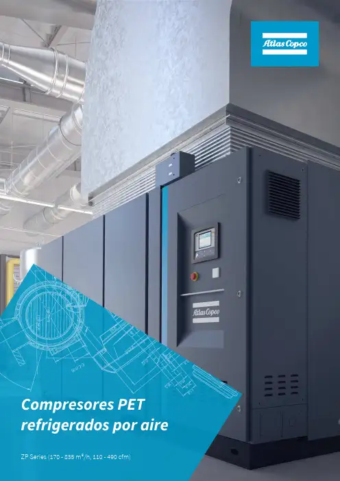
ZP Series (170 - 835 m³/h, 110 - 490 cfm)Compresores PET refrigerados por aireAument a t u p roductividad Como líder en tecnología de aire comprimido, siempre hemos creado el punto de referencia en innovación. Teniendo en cuenta la comodidad de t us operadores, nuestra nueva e innovadora serie refrigerada por aire viene equipada con una cubierta silenciosa y compacta como solución plug and play. La innovadora tecnología de monitoreo de caída de varilla establece un nuevo estándar en la tecnología de pistón. Esta es una forma completamente nueva de reducir t us costos operativos y aumentar el tiempo de actividad.Gracias al nuevo c ompresor r efrigerado p or a ire Z P, puede lograr ahorros inmediatos y a largo plazo en inversión , mantenimiento , tratamiento de agua y consumo de a gua.El ZP no n ecesita c ircuito d e e nfriamiento externo, esto significa que no hay torre de enfriamiento o unidad de enfriamiento, no tiene p atín d e b omba d e a gua y no hay tuberías. Esto reduce de f orma i nmediata y s ignificativa los costos d e i nversión y mantenimiento .Una contaminación accidental aumenta el riesgo de tiempo de inactividad de la producción y puede conducir a una costosa limpieza de t u proceso. Con la tecnología exent o de aceite, evita pérdidas de presión debido a menos tuberías y filtros en la red de aire, esto también conduce a ahorros inmediatos. No es solo t u producción lo que está en juego , sino también tu prestigio . Al proporcionar aire limpio de alta pureza, el ZP protege el prestigio d e t u empresa en el mercado , garantiza la seguridad y ayuda a proteger elmedioambiente.El ZP es silencioso,fácil de opera r y mantener,por loque esmuyapreciadoport usoperadores .Atlas Copco nosolo ofrece los compresores más fiables yeficientes, sino que también podemos ayudar t e a obtener la solución más rentable a lo largo de todo t u proceso. Diseñamos una gama de productos de aire comprimido líderes en su clase, totalmente optimizados para trabajar mejor juntos. Nuestra solución SMART AIRincluyesecadores,filtros,receptores deaire ycontroladores.Eli ge ZP , nuestra solución refrigeradapor Prote giendo t u p roducción yDiseño compacto y silenciosoSolución todo en uno 3aireprestigioUna interrupción en el suministro de aire conduce a una pérdida de producto, retrasos y reinicios costosos . La contaminación más pequeña de partículas no deseadas puede corromper la calidad de t u producto y afectar el rendimiento de los productos. Por otro lado, no querrás preocuparte por el aire. Solo tiene que estar allí, durante todo el día, en el flujo, la presión y la calidad correctos. Desea s concentrar t e en t u n egocio y lo que es más importante, en un resultado final sólido. Una organización de servicio profesional en todo el mundo garantizará su productividad y confiabilidad óptimas de las máquinas durante todo el día.Su socio comercial dePET•Conf iabilidad •E ficiencia energética •Calidad de aire• Menor costo de p ropiedad •Soporte local•Aumento de productividadBenefi cio sComo líder en tecnología de aire comprimido, los compresores de Atlas Copco entienden t us necesidades y han puesto su experiencia de más de un siglo a trabajar para su rentabilidad.•El único fabricante que utiliza tecnologíarefrigerada por aire adecuada para un entorno ambiente de 50 °C.•Estos refrigeradores eliminan la necesidad de instalar accesorios como torre de agua de enfriamiento, agua de enfriamiento.•Instalación rápida, poco espacio en el piso, sin mantenimiento para accesorios .• El diseño horizontal y las disposiciones dinámicamente equilibradas conducen a niveles de vibraci o n e s más baj a s.•Esta máquina viene con un diseño único del bastidor base y soportes especiales antivibraci o n es de elastómero, que no necesitan una base especial.1.Montaje único del enfriador2. Solución p lug and play5El único fabricante que integra sensores paraoptimizar la disponibilidad de la máquina, lo que lleva a aumentar la fiabilidad y reducir los cost o s de mantenimiento .•Cámaras completamente libres de aceite con anillos de pistón de PTFE y piezas de larga distancia con anillos de limpiaparabrisas .•No hay riesgo de contaminación, productos dañados o pérdidas por tiempo de inactividad operativa .•Reducción de los costos de mantenimiento ya que no hay necesidad de filtración de aceite .• La máquina estándar viene equipada con el motor IE3 TEFC de alta eficiencia , adecuado para funcionar a 50 °C en condiciones ambientales .•Estos motores de servicio continuo funcionan a bajas velocidades, diseñados para una vida útil más larga .•El diseño inteligente del protector de correa de 3 piezas garantiza un fácil montaje y mantenimiento .•Elektronikon® fácil de usar con potencial de conectividad mejorado.•Algoritmos inteligentes integrados para optimizar la presión del sistema y maximizar la eficiencia energética .La carcaza cerrada reduce drásticamente el nivel de ruido en comparación con los compresores de pistón , lo que aumenta la comodidad de trabajo .3. Estab e lecer un nuevo éstandar con la tecnología de caída de varilla4. Tecnología de pistón de aire exentode aceite5. Sistema de accionamiento eficiente conmotore s IE36. Sistema de monitoreo avanzado7. Bajo nivel de ruido•.Incluye indicaciones de advertencia, programación demantenimiento y visualización en línea del estado de la máquinaConf iabilidadEl uso de derivación de gas caliente garantiza un punto de rocío a presión estable y eliminala posibilidad de congelación por condensado. Nuestros secadores refrigerantes vienenequipados con intercambiadores de calor de acero inoxidable confiables. Los separadoresde agua confiables conducen aún más a un punto de rocío estable.Pantalla d igitalProporciona tranquilidad a través de un monitoreo preciso y la visualización del punto derocío a presión.Bajo nivel de ruidoVentilador de refrigeración especialmente diseñado para garantizar un bajo nivel de ruidode funcionamiento. El conjunto único del compresor rotativo con separador de líquidosintegrado conduce a vibraciones limitadas, las piezas móviles mínimas no solo garantizanun funcionamiento silencioso, sino que también reducen el riesgo de fugas.7Fácil mantenimientoAunque nuestros secadores refrigerantes están construidos con un tamaño compacto y pequeño, el fácil acceso a los componentes clave permite un mantenimiento rápido y sin problemas.9Más del 80% del costo del ciclo de vida de un compresor es absorbido por la energía que consume. Además, la generación de aire comprimido puede representar más del 40% de lafactura total de electricidad de una planta. Para reducir t us cost o s energéticos, Atlas Copco fue pionera en la tecnología de variadores de velocidad (VSD) en la industria del aire comprimido. VSD conduce a un importante ahorro de energía, al tiempo que protege el medio ambiente para las generaciones futuras. Gracias a las continuas inversiones en esta tecnología, Atlas Copco ofrece la gama más amplia de compresores VSD integrados del mercado .Reducir los costos de energíaLa tecnología VSD de Atlas Copco sigue de cerca la demanda de aire ajustando automáticamente la velocidad del motor. Esto se traduce en un gran ahorro de energía de hasta el 35% . El costo del ciclo de vida de un compresor se puede reducir en un promedio del 22% . Además, la reducción de la presión del sistema con VSD minimiza drásticamente el uso de energía en toda su producción .¿Qué tiene la tecnología con la que cuenta Atlas Copco en los VSD integrado s ?• El E lektronikon ® controla tanto el compresor como el convertidor integrado, garantizando la máxima seguridad de la máquina dentro de los parámetros .•La selección flexible de presión con VSD reduce los costos de electricidad .• Diseño específico del convertidor y del motor (con rodamientos protegidos ) para la mayor eficiencia en todo el rango de velocidad .•Motor eléctrico diseñado específicamente para bajasvelocidades de funcionamiento con una clara atención a los requisitos de enfriamiento del motor y enfriamiento del compresor .•Las mejoras mecánicas aseguran que todos los componentes funcionen por debajo de los niveles de vibración críticos en todo el rango de velocidad del compresor.•Un convertidor de frecuencia altamente eficiente en un cubículo garantiza un funcionamiento estable a altas temperaturasambiente de hasta 50 ° C / 122 ° F (estándar hasta 40 ° C / 104 ° F).•La banda de presión neta se mantiene dentro de 0.10 bar, 1.5 psi .Ahorro energético de hasta un35%Accionamiento de compresor dedicadoAtlas Copco fue pionero en los primeros compresores VSD. Aprendimos de la experienciade campo que los accionamientos tradicionales sufren en aplicaciones de compresorespor polvo, humedad, sobrecorrientes, etc. Era hora de reunir toda esta experiencia ydesarrollar un accionamiento hecho a medida para los compresores de Atlas Copco.Diseñado para la robustezNeos tiene un grado de protección IP5X. Todos los componentes de la unidad estánprotegidos del polvo y la h umedad, g racias a u na r obusta c arcasa d e a luminio. E l N eosfuncionará sin p roblemas e n l as condiciones más duras.La simplicidad es claveNeos ha sido diseñado internamente por Atlas Copco. La atención se centra en lacompac tación,la simplicidad y la facilidad de uso.11Diseño ecológicoMenos componentes, también significa que el Neos tiene menos impacto en el medio ambiente al final de su ciclo de vida. Para nosotros, la sostenibilidad a largo plazo es una parte crucial de la innovación.El controlador de la unidad Elektronikon® está especialmente diseñado para maximizar el rendimiento de t us compresores y equipos de tratamiento de aire en una variedad de condiciones. Nuestras soluciones le proporcionan beneficios clave como una mayoreficiencia energética, un menor consumo de energía, tiempos de mantenimiento reducidos y menos estrés... menos estrés tanto para ti como para todo t u sistema de aire..Seguimiento ycontrolLa pantalla a color de alta resolución le brinda una lecturafácil de entender de las condiciones de funcionamiento del equipo .•Los iconos claros y la navegación intuitiva lebrindan acceso rápido a todas las configuraciones y datos importantes .• Monitoreo de las condiciones de funcionamiento del equipo y el estado de mantenimiento; trayendo esta información a t u a tención cuando sea necesario .•Operación del equipo para entregar de manera específica y confiable a sus necesidades de aire comprimido .•Funciones integradas de control remoto ynotificaciones proporcionadas de serie, incluida la comunicación basada en Ethernet fácil de usar .•Soporte para 31 idiomas diferentes, incluidos los idiomas basados en caracteres .La inteligencia es parte del paquet eSupervis a t us compresores a través de Ethernet con el controlador de la unidad Elektronikon®. Las funciones de monitoreo incluyen indicaciones de advertencia, apagado del compresor y programación demantenimiento. Hay disponible una aplicación de Atlas Copco para teléfonos iPhone/Android, así como para tabletas iPad y Android. Permite el monitoreo de la punta de los dedos de t u sistema de aire comprimido a través de t u propia red segura .Monitoreo en líneaLa mayoría de los procesos de producción crean niveles fluctuantes de demanda que, a su vez, pueden crear desperdicio de energía en períodos de bajo uso. Utilizando el controlador gráfico de la unidad Elektronikon®, puede crear manual o automáticamente dos bandas de presión del sistema diferentes para optimizar el uso de energía y reducir los costos en tiempos de u so s bajos .Punto de a juste de pre s ión dual13Supervis a t u instalación de aire comprimido con SMARTLINKConocer el estado de su equipo de aire comprimido en todo momento es la forma más segura de lograr una eficiencia óptima y la máxima disponibilidad .Apuesta por la eficiencia energéticaInformes personalizados sobre la eficiencia energética de t u sala de compresores .Aument a el tiempo de actividadTodos los componentes se reemplazan a tiempo, lo que garantiza el máximo tiempo de actividad .Ahorr a dineroLas alertas tempranas evitan averías y pérdidas de producción .SMARTLINKServicio S MARTLINKUn clic del mouse revela el registro de servicio en línea. Obt én cotizaciones de piezas y servicio adicional de forma rápida y sencilla .El tiempo de actividad también le envía un correo electrónico o mensaje de texto cada vez que una advertencia requiere t u atención .Energía SMARTLINKEnergy t e ofrece informes personalizados sobre la eficiencia energética de t u sala de compresores, de conformidad con la norma ISO 50001.Evolucionando hacia la gestión del aire comprimidoTiempo de actividad de S MARTLINKZP 55-110-132 (FS/VSD)ZP 55405808631028518255753621 x 2110 x 2190ZP 55 VSD405808631028518255753621 x 2110 x 2190ZP 110405801916926324061101506296 x 2218 x 2196ZP 110 VSD405801916926324061101506296 x 2218 x 2196ZP 132405802318377664921321806296 x 2218 x 2196ZP 132 VSD405802318377664921321806296 x 2218 x 2196(1) Reference conditions : Absolute inlet pressure: 1 bar (14.5 psi).Temperatura del aire de entrada: 20°C, 68°F15Atlas Copco MexicanaTeléfono:+525522820732 .mx。
空压机说明书内蒙古京隆发电有限公司空压系统技术文件内蒙古京隆发电有限公司空气压缩机技术文件需方:内蒙古京隆发电有限公司供方:江阴市泰拓机械设备有限公司二OO九年九月目录1. 前言2. 设备名称、型号、技术参数3. 供货范围4. 空压机技术特点5. 设计标准6. 技术资料交付7. 验收标准8. 包装、运输及交货9. 质量保证10. 合同执行表1.0前言康普艾:骄傲的历史康普艾公司是一骄傲的历史家历史悠久的空压机专业制造商,总部设在英国伦敦。
目前康普艾庞大的跨国机构,在欧洲、美洲、非洲和亚太地区都有十分活跃的业务活动。
经过二百多年的经营,康普艾的业务扩展到全球95个国家和地区,在23个国家有生产基地,包括康普艾美国公司、康普艾英国公司(原名BroomWade、Holman)、康普艾里德迪驰公司(原名Hydrovane,国内注册风霸商标)、康普艾法国公司、康普艾伊普斯威奇公司(原名Reavell)、康普艾德国公司(原Demag 集团螺杆空压机部分)及上海康普艾压缩机有限公司(中国)等。
自上世纪下半页,多级化世界格局促进了全球的和平进程,使更多的先进技术能够进入民用领域,康普艾也加入这一潮流,将更多的研发、资金投入对产品、用户和环保的关注中。
很多商业集团在纷纷意识到高技术机械领域的迅速发展后,也积极支持该行业的进步。
继1999年英国英维思集团购并康普艾后,英国财务集团Alchemy Partner于2002年收购康普艾股权,目前与英维思一同成为大股东。
相信通过集中人力、财力、物力,未来的康普艾的历史将更辉煌。
上海康普艾压缩机有限公司是英国康普艾集团公司和上海大隆机器厂于1994年6月筹资2000万美元共建的,专业生产和销售空气压缩机。
作为康普艾集团公司在远东主要的生产基地,公司设在上海市松江工业开发区,占地面积36,897平方公尺。
自成立以来,上海康普艾压缩机有限公司分别在部分国内主要城市成立销售办事处和维修中心。
空气压缩机使用说明书一、操作注意事项:1、压缩机必须定期检修,并保证在良好工作状态下工作。
2、在压缩机组运行前,必须注意不可有人在机器上进行检修工作。
3、压缩机应在技术规范规定的范围内运行。
4、不可以在可能吸入易燃、有毒或腐蚀性蒸汽或气体的环境中运行压缩机。
5、注意人不可以接触管路系统,尤其是排气管或是在运行中的高温部件。
6、压缩机组运行时,操作人员不可做其他别的工作,以适时监控压缩机组的运行状态。
二、维修工作注意事项:1、维修工作只可在停机并完全放空的压缩机上运行。
若有必要,将压缩机系统内的高压气体放空。
首先应断开电源控制箱的总闸,为了防止误开机组,应将总闸锁上,或者贴一张相应的指示标签。
2、开始工作前,应全部打开凝液分离器上的手动排水阀,使得压缩机组完全放空,没有压力。
3、每次修理或改造安全设备时,如果要求有修改后检查合格证的,必须经有关监测主管部门重新验收认可。
4、在压缩机组上,只可用原装备件和推荐使用的零部件进行维修。
5、在维修时要严格保持清洁,拆下的零件应置于干净的地方,并对不同的零件采取用布、纸或胶布遮盖起来,以防尘污。
6、维修后,检查一下确定没有工具,零部件和抹布留在压缩机组上面或者里面。
7、压缩机组完全降温前,决不可用易燃溶剂清洗零部件。
零部件用溶剂清洗后,然后用压缩空气将零部件吹洗干净。
8、用压缩空气吹设备时,应十分小心,并戴护目镜。
三、压缩机的主要性能参数:a、公称容积流量:3m3/minb、吸气压力:0.1MPac、额定排气压力: 4.0MPad、吸气温度:≤45℃e、各级排气温度:<180℃f、输气温度:≤50℃g、压缩介质:空气h、冷却水耗量:≥3.5 m3/hi、润滑油温度:≤70℃j、气缸直径:一级φ285mm二级φ155mm三级φ75mm k、活塞行程:95mml、转速:740r/minm、配备动力:Y280M-8,740r/min,450KW,AC380V/50HzIP44 B3 n、压缩机外形尺寸(长×宽×高):~2350×1900×1500(mm) o、全机重量: 2500kgp、震动烈度:≤28.0q、各级排气压力:一级排气压力:0.27~0.37MPa二级排气压力:1.2~1.39MPa三级排气压力:4.0MPa四、气路系统:气路系统的作用,主要是将气体引向压缩机,经压缩机各级压缩之后,再引向使用场所,本机的主要气路流程示意如下:其中空气滤清器、一级气缸、一级冷却器、二级气缸、二级冷却器、二级油水分离器、三级气缸、三级冷却器、三级油水分离器和以上部件连接的管道组成压缩机的气路主管路,排除油、水用的排污管路以及连接压力表的管路和控制管路等组成压缩机气路的辅助管路;用户在使用该机前,必须增加后续管道和阀门分别与送气接头、排污接头相连接,以备把压缩空气送至使用场所和把油水引至合适的位置排放掉,本机的排污是自动排污,排放的时间间隔约为20~30min排放一次,排放时间约为10s,用户可根据当地的空气湿度进行适当的调整。
空气压缩机操作说明书操作说明书一、使用前准备空气压缩机是一种常用的机械设备,用于将空气压缩成高压气体。
在操作空气压缩机之前,需要进行以下准备工作:1. 检查设备:首先,仔细检查空气压缩机的外观和内部结构,确保设备无损坏和漏气现象。
检查油液和冷却系统是否正常运行。
2. 安全措施:操作空气压缩机需要注意安全事项。
穿着防护服和安全鞋,戴上安全帽和护目镜。
确保操作区域通风良好,并保持设备周围的干燥和整洁。
3. 验证备件:检查空气压缩机的备件和附件是否齐全,并进行必要的更换或修理。
确保备件的质量和适用性。
二、操作步骤操作空气压缩机需要按照以下步骤进行:1. 启动:首先,检查电源,确保供电稳定。
打开空气压缩机的电源开关,并观察仪表板以确保设备正常运行。
2. 调整压力:根据需要调整空气压缩机的工作压力。
使用调压阀来控制输出压力,并根据实际需求进行调整。
3. 加油:在操作空气压缩机之前,需要确保油液充足。
根据设备说明书,选择适当的油液,并将其添加到相应的位置。
4. 启动压缩机:根据操作面板上的指示,按下启动按钮,启动空气压缩机。
确保设备正常启动,并观察运行状态。
5. 监测运行:在空气压缩机运行期间,需要定期监测设备的运行状态。
注意仪表板上的压力和温度指示,并确保设备处于正常工作范围内。
三、维护和保养为了确保空气压缩机的长期稳定运行,需要进行维护和保养工作:1. 清洁:定期清洁空气压缩机的外壳和内部部件。
使用干净的布或气压枪除去灰尘和污垢,保持设备的干燥和清洁。
2. 检查油液:定期检查油液的质量和量。
根据操作手册的要求,更换油液或添加适量的润滑油。
3. 维修和更换:当空气压缩机出现故障或磨损时,需要及时进行维修和更换部件。
确保备件的质量和适用性,并按照操作手册的要求进行维修。
4. 定期检测:定期进行设备的维修和检测,以确保设备的安全性和性能。
根据操作手册的指导,进行必要的测试和校准。
四、注意事项在操作空气压缩机时,需要注意以下事项:1. 遵守使用规定:严格按照操作手册和相关规定进行操作。
空压机使用说明书空压机使用说明书一、产品介绍空压机是一种将大气中的气体压缩成高压气体的设备。
本文档将详细介绍空压机的使用方法和注意事项。
二、安全须知1、操作前,请务必仔细阅读本说明书,了解各个部件的功能和操作方法。
2、在操作过程中,严禁将手指、头部或其他物体放入机器内部。
3、使用前应检查电源线插头是否完好,并确保插座接地良好。
4、在操作过程中,严禁将待压缩气体喷射到人体上,以免引起伤害。
三、机器操作1、启动和关闭a:将开关拨至“ON”位置,待机器启动后即可正常工作。
b:在使用完毕后,将开关拨至“OFF”位置,停止机器运行。
2、压力调节a:使用压力表来调节空压机的输出压力,确保符合所需工作压力。
b:注意不要超过空压机的额定工作压力,否则可能会导致设备损坏或危险事故。
3、润滑油更换a:根据使用频率和工作环境,定期更换润滑油。
b:在更换润滑油时,务必按照说明书的要求进行操作。
4、清洁和维护a:定期清洁空压机的滤网和冷却器,以确保机器正常运行。
b:注意不要用水直接清洗机器,以免损坏机器部件。
四、故障排除1、机器无法启动a:检查电源是否正常连接。
b:确认开关是否处于正确位置。
2、压力过高或过低a:检查压力表是否正常工作。
b:检查机器是否存在漏气的情况。
3、异常噪音或振动a:检查机器是否处于稳定的工作状态。
b:确认机器各个部件是否牢固固定。
五、附件本文档涉及的附件包括:1、产品说明书2、电源线3、压力表六、法律名词及注释1、法律名词:压力调节器,指调节空压机输出气体压力的装置。
2、注释:压力调节器通常由压力表和调节装置组成,用于确保空压机输出的气体压力处于正常范围内。
空压机说明书一、工作原理皮带传动式单级压缩机是由电机(马达)经三角带,驱动压缩机主机皮带轮带动曲轴,作旋转运动,空气进入空气滤清器通过进气阀进入气缸,通过连杆使活塞在气缸内作往复运动压缩空气,引起气缸容积变化,在压缩行程中,由于气缸容积的缩小,气缸内的空气压缩到额定排气压力后,通过排气阀的作业,经过排气管、单向阀进入储气罐。
皮带传动式两级压缩机简言之:是由一级压缩空气通过连接管再进入另一只气缸,将气缸内空气压缩到额定排气压力后,通过排气阀的作用,经过排气管、单向阀进入储气罐,压缩机装有自动压力开关控制电机,当储气罐的空气压力达到所调整的排气压力时(出厂前已调整好,请勿自行调整),空压机自动停机,当储气罐的空气压力降低0.4MPa-0.5MPa(低压)或0.6MPa-0.8MPa(高压)时,压缩机会重新启动,从而使储气罐里的压缩空气的压力保持在一定的范围内,达到自动控制的目的。
二、安装及准备1、使用本机前务必检查机头,皮带轮螺丝及各部件螺丝是否松动,并锁紧之。
2、使用本机前,务必详细阅读本机使用说明书。
3、空压机必须放置于清洁、干燥、通风的地方。
皮带轮传动方向的一侧靠墙或其它物品时,最小距离应大于30cm以上,[wiki]环境[/wiki]温度-20℃-40℃为宜。
4、启动前必须检查空压机油量是否足够,标准油位应在油镜中红圈(或红线)的中线位置,油位不得过高或过低。
5、外接电源时请参照本说明书中(空压机外接电源配线标准)配电源线。
在接线前,务必按空压机出厂时的引出线连接,禁止的空压机所配电机接线盒,内外接电源。
6、确认电源电压及频率是否符合本机产品合格证所规定的电压及频率,安装空压机时,必须安装塑料外壳式断路器(空气开关),禁止使用闸刀控制空压机。
7、确认所购空压机是否符合您所需要的额定排气量和额定排气压力。
三、使用、维护和保养1、使用前应检查压缩机皮带轮转动方向,是否符合压缩机防护罩所粘贴的箭头方向。