伦茨9300系列驱动系统..
- 格式:ppt
- 大小:4.31 MB
- 文档页数:37
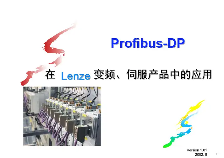
Profibus-DP总线在Lenze变频、伺服产品中的应用Version 1.01目录1. Profibus-DP 总线基础在系统中配置Lenze产品2. Profibus-DP3. 过程通道通讯编程与举例4. 参数通道通讯编程与举例5. 常见问题解答1.1 面向现场级与车间级的数字化通讯网络伦茨变频、伺服驱动产品属于现场级的从站设备,即伦茨公司总 PROFIBUS-DP 线通信模块支持通信方式。
1. Profibus-DP 总线基础1.2 -主从通讯结构1. Profibus-DP总线基础1.3 过程通道与参数通道通讯PROFIBUS PLC /主站()可以与伦茨变频伺服产品之间进行—快速的循环数据传输Process Channel 过程通道()通信,/ ——以及可读写所有伦茨产品内部参数的非循环数据传输Parameter Channel 参数通道()通讯。
1. Profibus-DP 总线基础对于过程通道通讯而言,总线系统的响应速度主要取决于:(1) 总线波特率(2) DP从站的数量(3) 每个从站所配置的过程通讯字的数目(4) 每个从站是否有参数通道通讯用户可以依据上表作为参考:32当总线具有个从站,数据传输率12M为,每个从站配置一个过程通1ms讯字时,总线循环时间为。
/伦茨变频器伺服控制器对于通讯请求的响应时间为:3 ms ~ 5 ms过程通道:30 ms ~ 50 ms参数通道:1.4 通讯响应时间估算1. Profibus-DP 总线基础在Profibus-DP 系统中配置Lenze 产品1. Profibus-DP 总线基础在系统中配置产品2. Profibus-DP Lenze3. 过程通道通讯编程与举例4. 参数通道通讯编程与举例5. 常见问题解答端口、通讯模块与系统组态2.1 AIF/FIF(1)2.1.1不同的变频/伺服系统具有不同的通信接口,及接受数量不同的过程通讯字,归纳如下:通用变频器:端口,个过程字8200 AIF 2经济型矢量变频器:端口,个过程字;8200Vector AIF 3端口,个过程字FIF 10现场安装型矢量变频器:端口,个过程字8200Motec FIF10现场安装型智能软启动器:端口,个过程字Starttec FIF10高性能矢量变频器:端口,个过程字9300Vector AIF4系列高级伺服控制器:端口,个过程字9300Servo AIF4带内置的高级伺服控制器::个过程字9300ServoPLC PLC AIF12:高性能小型:端口,个过程字DrivePLC PLC AIF 122.1 AIF/FIF (2)端口、通讯模块与系统组态2.1.2 AIF 端口与通信模块性能特点汇总:AIF AUTOMATION INTERFACE :;伦茨用于此端口的Profibus-DP 通信模块为EMF2133IB//PLC 8200Motec Starttec 适配伦茨的所有变频伺服产品(除、以外) PROFIBUS-DP 适配的总线系统中作为从站 9.6k 12M自适应总线波特率从至 DIP PROFIBUS-DP 从前面板通过开关即可设置中的站址 12过程通道通讯最多可设置个过程字。
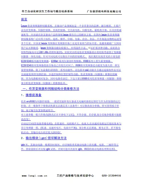
前言Lenze伦茨变频器和伺服系统,在驱动产品领域也是一个非常著名的品牌,源自德国,主要产品包括变频器,伺服控制器,直流控制器,交直流电机,伺服电机,磁粉离合器,以及齿轮减速机等,应该说在涉及驱动产品的领域lenze都有自己的解决方案。
在国内lenze伦茨变频器和伺服系统广泛应用于纺织、造纸、烟草、印刷、包装、冶金、食品、汽车制造及物料运送等多个行业。
应该说lemze变频器在变频器市场上还是有着相当的知名度,也越来越被广大国内用户认可和接受。
lenze变频器功能比较强大,应用选件丰富,可以扩展多种功能,良好的力矩特性(最高可达180%60s的转矩提供),比较突出的是伦茨变频器设计的时候考虑到了变频器伺服器一体化功能,针对不同电机可以做出不同的控制模式。
现在我们比较常见的主要包括8220/8240系列通用变频器,8200ev系列矢量闭环变频器,9300系列工程矢量变频器。
8220/8240系列变频器投放市场也已有较长时间了,9300系列变频器是功能更为强大的一种矢量型变频器,除了先前我们讲到的一系列功能外,还包括双pid功能并且通过选装组件还可以完成速度/转矩切换控制、步进控制和位置控制等功能。
伦茨变频器(伺服器)维修比较麻烦,因为电路板相对复杂,同时电路有涂层,下边主要以9300系列伦茨变频器(伺服器)维修来分析伦茨变频器(伺服器)的维修技术。
一、伦茨变频器和伺服结构分类维修方法1、维修前准备伦茨evs9300为伺服控制器,一般采用旋转变压器或光电编码器的反馈信号作为控制器的运行控制,在一般条件下维修试机都无法满足其工况条件!可以修改部分参数;即可使用端子控制。
端子编号位置参照说明书。
对上述参数一般只作修改(修改后在不掉电下记忆),不作存储。
若存储,部分其他参数都可能跟着改变!启动运行时(若连接普通电机):在低速时,电机噪声大,电流大;在高速时电机运行情况基本与其它变频器一致,(低速、高速时电压、电流应平衡);部分机无法调速,都为正常。

机械运动解决方案Linear Motion. Optimized.丹纳赫下属企业Linear Motion. Optimized.Thomson -Linear Motion. Optimized.70多年的全球应用经验。
这些行业包括:包装、工厂自动化、物料运输、Thomson是质量、创新、按时交货、可控成本和低风险的代名词,是值得信赖的品牌。
网站获取大量的产品及应用信息。
同时,网站还提供可下400-666-1802或发送电子************************。
Thomson如何协助您为下一应用而确定产品性能、使用寿命和成本的最佳平衡。
2000余家分销合作伙伴中的任意一家。
丹纳赫业务系统-为您的企业构建可持续竞争优势。
它由一组我们日常使用的成熟且成功的工具组成,可以可持续、积极消除企业各个方面资源浪费的Kaizen原理为基础。
通过可使您缩短产品上市时间,实现无与伦比的产品质量、服务、可靠性和生全球化支持、本地化服务应用中心 全球生产运营设施 全球设计和工程中心应用中心全球生产运营设施全球设计和工程中心机械运动解决方案 3纺织包装医疗非公路用机动设备Linear Motion. Optimized.直线滚珠衬套轴承和60 Case TM轴系60年前,Thomson发明了滚珠衬套轴承,此后一直是该领域公认的领导者。
其直线产品提供低摩擦、顺畅、精确的直线运动。
Thomson提供全面的轴承及配件系列,可充分满足实际应用中最佳性能产品的广泛要求。
RoundRail™直线滚珠衬套轴承● 业界最广泛的产品系列● 尖端分割技术● 超过60年的产品创新和无与伦比的服务60 Case™轴系● 与Thomson 滚珠衬套轴承配合使用时, 60 Case™轴系的使用寿命比竞争产品长50%● 提供多种专有材料和表面处理● 直径:1/8 inch到4 inch,5 mm到80 mm● 长度:可达25 ft(7.6 m)● 定制加工能力-驱动轴、主轴、导杆、卷筒等直线导轨从超轻型T系列(传动级导轨)和紧凑型不锈钢MicroGuide到超硬型500系列滚柱导轨(机床级),我们高性能直线导轨装置的“一站式服务”可满足您的所有直线导轨需求。
水星二代(MERCURY2)GigE数字相机应用说明书版本:V2.0.0本手册中所提及的其它软硬件产品的商标与名称,都属于相应公司所有。
本手册的版权属于中国大恒(集团)有限公司北京图像视觉技术分公司所有。
未得到本公司的正式许可,任何组织或个人均不得以任何手段和形式对本手册内容进行复制或传播。
本手册的内容若有任何修改,恕不另行通知。
© 2023中国大恒(集团)有限公司北京图像视觉技术分公司版权所有网站:公司总机:************客户服务热线:400-999-7595销售信箱:************************支持信箱:**************************首先感谢您选用大恒图像产品,水星二代(MERCURY2)GigE接口数字相机是我公司水星一代(MERCURY)数字相机的升级产品,在相机功能上有所增加,结构上有所改进。
水星二代GigE相机包括标准版(MER2-G(-P)系列),Pro版(ME2P-G-P系列)、Super版(ME2S-G-P系列)和China版(ME2C-G(-P)系列)。
相机采用了GigE标准接口,安装、使用方便,适用于工业检测、医疗、科研、教育、安防等领域。
水星二代GigE接口数字相机是微型相机,对于相机尺寸要求苛刻的用户,它们将会是一个不错的选择。
本手册详细介绍了水星二代GigE接口数字相机的应用。
概述 (1)系列概述 (1)型号名称说明 (1)遵循的标准 (1)相关文档及软件下载 (1)注意事项及认证声明 (2)安全声明 (2)使用注意事项 (2)EMI、ESD注意事项 (3)使用环境注意事项 (3)相机机械安装注意事项 (3)认证声明 (3)安装指南 (5)主机端准备 (5)3.1.1. 用户软件组成 (5)3.1.2. 用户软件接口 (5)相机供电 (6)相机驱动安装 (7)3.3.1. 系统要求 (7)3.3.2. 驱动安装 (7)相机IP配置 (7)打开相机采集 (8)性能参数 (9)重要参数解释 (9)4.1.1. 关于光谱响应图 (9)MER2-G(-P) 系列 (9)4.2.1. MER2-041-302GM/C(-P) (9)4.2.3. MER2-134-90GM/C(-P) (12)4.2.4. MER2-137-90GM/C(-P) (14)4.2.5. MER2-160-75GM/C(-P) (15)4.2.6. MER2-202-60GM/C(-P) (17)4.2.7. MER2-203-30GC-P-L (18)4.2.8. MER2-204-30GC-P-L (20)4.2.9. MER2-231-41GM/C(-P) (21)4.2.10. MER2-302-37GM/C(-P) (23)4.2.11. MER2-503-23GM/C(-P) (24)4.2.12. MER2-503-23GM-P POL (26)4.2.13. MER2-507-23GM/C(-P) (27)4.2.14. MER2-507-23GM(-P) NIR (29)4.2.15. MER2-532-22GM/C (30)4.2.16. MER2-630-18GM/C(-P) (32)4.2.17. MER2-1070-10GM(-P) (33)4.2.18. MER2-1220-9GM/C (35)4.2.19. MER2-2000-6GM/C(-P) (36)ME2C-G(-P) 系列 (38)4.3.1. ME2C-041-302GM/C(-P) (38)4.3.2. ME2C-051-120GM/C(-P) (39)4.3.3. ME2C-137-90GM/C(-P) (41)4.3.4. ME2C-160-75GM/C(-P) (42)4.3.5. ME2C-202-60GM/C(-P) (44)4.3.6. ME2C-203-30GC-P-L (45)4.3.7. ME2C-204-30GC-P-L (47)4.3.8. ME2C-231-41GM/C(-P) (48)4.3.9. ME2C-240-48GM/C(-P) (50)4.3.10. ME2C-302-37GM/C(-P) (51)4.3.11. ME2C-503-23GM/C(-P) (53)4.3.12. ME2C-507-23GM/C(-P) (54)4.3.13. ME2C-507-23GM(-P)-NIR (56)4.3.14. ME2C-532-22GM/C (57)4.3.15. ME2C-630-18GM/C(-P) (59)4.3.16. ME2C-1070-10GM(-P) (60)4.3.17. ME2C-1220-9GM/C (62)4.3.18. ME2C-2000-6GM/C(-P) (63)ME2S-G-P 系列 (65)4.4.1. ME2S-1260-9GM/C-P (65)ME2P-G-P 系列 (66)4.5.1. ME2P-231-41GM/C-P (66)4.5.2. ME2P-503-23GM/C-P (68)4.5.3. ME2P-560-21GM/C-P (69)4.5.5. ME2P-900-13GM/C-P (72)4.5.6. ME2P-1220-9GM/C-P (74)4.5.7. ME2P-1230-9GM/C-P (75)4.5.8. ME2P-1840-6GM/C-P (77)4.5.9. ME2P-2000-6GM/C-P (78)4.5.10. ME2P-2621-4GM/C-P \ ME2P-2622-4GM/C-P (80)4.5.11. ME2P-2621-4GM-P NIR \ ME2P-2622-4GM-P NIR (82)机械尺寸 (84)相机尺寸 (84)光学接口 (88)固定块尺寸 (88)滤光片及镜头 (89)滤光片规格参数及响应图 (89)镜头选型参考 (90)6.2.1. HN-2M 系列定焦镜头 (91)6.2.2. HN-5M 系列定焦镜头 (91)6.2.3. HN-6M 系列定焦镜头 (92)6.2.4. HN-20M 系列定焦镜头 (92)6.2.5. HN-P-6M 系列定焦镜头 (93)6.2.6. HN-P-10M 系列定焦镜头 (93)6.2.7. HN-P-20M 系列定焦镜头 (94)6.2.8. HN-P-25M 系列定焦镜头 (94)6.2.9. HN-P 系列8K~16K线扫镜头 (94)电气接口 (95)LED灯状态 (95)网口 (95)I/O接口 (95)7.3.1. I/O接口定义 (95)MER2/ME2P系列 (95)ME2S/ME2C系列 (96)Line0(光耦隔离输入)电路 (97)Line1(光耦隔离输出)电路 (100)Line2/3(双向)电路 (102)7.3.2.3.1. Line2/3配置成输入管脚 (103)7.3.2.3.2. Line2/3配置成输出管脚 (105)功能定义 (108)I/O控制 (108)8.1.1. 配置输入引脚 (108)8.1.2. 配置输出引脚 (109)8.1.3. 读取引脚状态 (113)图像采集控制 (114)8.2.1. 开始采集/停止采集 (114)开始采集 (114)停止采集 (115)8.2.2. 采集模式 (117)8.2.3. 触发类型选择 (117)8.2.4. 触发模式切换 (119)8.2.5. 连续采集及其配置 (120)8.2.6. 突发采集模式 (120)8.2.7. 软触发采集及其配置 (121)8.2.8. 外触发采集及其配置 (121)8.2.9. 交叠曝光和非交叠曝光 (122)8.2.10. 设置曝光 (123)设置曝光模式 (123)设置Sensor曝光模式 (125)设置曝光时间模式 (127)设置曝光时间 (128)8.2.11. 曝光延迟 (128)基本属性设置 (132)8.3.2. 像素格式 (132)8.3.3. ROI (137)8.3.4. 自动曝光和自动增益 (137)自动曝光自动增益ROI设置 (137)自动增益 (138)自动曝光 (139)8.3.5. 测试图 (139)8.3.6. 参数组 (141)8.3.7. 用户自定义名称 (143)8.3.8. 时间戳 (143)8.3.9. Binning (144)8.3.10. 像素抽样 (146)8.3.11. 镜像翻转 (147)8.3.12. 数字移位 (149)8.3.13. 采集状态 (150)8.3.14. 黑电平和自动黑电平 (151)黑电平 (151)自动黑电平 (151)8.3.15. 取消参数范围限制 (151)8.3.16. 用户数据区 (159)8.3.17. 定时器 (159)8.3.18. 计数器 (160)图像处理 (161)8.4.1. 环境光源预设 (161)8.4.2. 自动白平衡 (161)自动白平衡ROI (161)自动白平衡调节 (162)8.4.3. 颜色转换 (163)8.4.4. 饱和度 (164)8.4.5. Gamma (165)8.4.7. 平场校正 (167)平场校正系数的求取和预览 (168)系数的读取和保存 (169)文件的读取与保存 (169)8.4.8. 查找表 (169)8.4.9. HDR (170)8.4.10. 降噪 (171)图像传输 (171)8.5.1. 帧率计算 (171)8.5.2. 最大帧率 (172)8.5.3. 包长 (179)8.5.4. 包间隔 (179)8.5.5. 预留带宽 (180)8.5.6. 传输控制 (180)8.5.7. 帧存控制 (180)事件 (181)8.6.1. 曝光结束事件 (182)8.6.2. 图像帧数据丢弃事件 (182)8.6.3. 帧存不为空事件 (182)8.6.4. 触发信号溢出事件 (182)8.6.5. 事件队列溢出 (182)8.6.6. 帧高速连拍开始触发信号溢出事件 (183)8.6.7. 帧开始触发信号等待事件 (183)8.6.8. 帧高速连拍开始触发信号等待事件 (183)软件使用 (184)IP配置 (184)9.1.1. 界面 (184)9.1.2. 使用说明 (185)枚举 (185)自动配置IP (185)显示信息 (186)修改相机IP地址 (187)修改相机IP配置方式 (187)修改用户自定义名称 (188)复位设备和重连设备 (188)9.1.3. 注意事项 (188)IP地址格式检查 (188)用户自定义名称长度限制 (189)提示信息 (189)帧率计算工具 (189)查找表生成插件 (190)9.3.1. 界面 (190)9.3.2. 使用说明 (192)使用场景 (192)基准Lut选择 (192)调整Lut (194)保存查找表 (195)读取Lut (195)9.3.3. 注意事项 (196)从设备中读取 (196)Lut写入设备 (196)目录结构 (196)平场校正插件 (196)9.4.1. 界面 (197)9.4.2. 使用说明 (198)平场校正执行步骤 (198)采集亮场图像 (198)执行平场校正 (199)校正数据从设备读取/写入设备 (199)校正数据从文件加载/保存到文件 (199)9.4.3. 注意事项 (200)平场校正实现方式 (200)静态坏点校正插件 (201)9.5.1. 界面 (201)9.5.2. 使用说明 (203)执行静态坏点校正步骤 (203)捕获图像 (203)静态坏点校正 (203)坏点数据文件使用 (204)常见问题处理 (205)版本说明 (206)联系方式 (210)销售联系方式 (210)技术支持联系方式 (210)总部及各办事处联系方式 (210)1.概述概述系列概述水星二代(MERCURY2)GigE数字相机是由大恒图像自主研发的成熟产品,性能出色、设计小巧、价格实惠、安装、使用方便。

◆主要更新项目:--------------------------------------------------------1、本系统通过微软官方正版验证及永久在线升级,不黑屏2、安全补丁打全至2010年06月15日3、更新SA TA\SCSI\RAID驱动,兼容各类新旧计算机4、更新驱动,自动识别台式机与笔记本电脑来解压不同的驱动程序5、更新DirectX 9.0c 2010.06版,更好的支持大型网络游戏等6、更新Adobe Flash Player V10.1.53.64正式版7、软件更新及可选安装的工具箱列表如下:├─常用软件(默认集成)│├─WinRAR 3.93简体中文正式版│├─极品五笔输入法7.0正式版│├─搜狗拼音输入法5.0正式版│├─Windows Media Player 10.0中文版│└─系统美化主题16款+50张精美壁纸+5个精美屏保+3款鼠标方案│├─装机人员工具(可选安装)│├─备份还原工具│├─局网共享工具│├─快捷设置工具│├─杀毒修复工具│├─系统维护工具│└─硬件维护工具│├─实用绿色软件(可选安装)│├─FLASH播放器│├─ISO编辑软件│├─OEM品牌修改器│├─PDF浏览器3.0│├─定时关机小软件│├─ONES迷你刻录软件│├─网络质量测试软件│├─微软虚拟光驱│└─屏幕抓图软件◆系统概述:----------------------------------------本系统以适合电脑公司和维护人员快速装机为目的,以微软0805月官方发布的Windows XP SP3免激活VOL原版为母盘,精心制作而成,采用微软内部封装技术,实现Longhorn的detecthal技术全自动检测正确电源模式,准确率接近100%,集成最新SA TA\SCSI\RAID驱动,以达完美克隆恢复到任何机型之目的!确保系统稳定和运行顺畅,以达到用户满意!◆系统特点:----------------------------------------1、系统安装全过程约6分钟,部分机子可达5分钟,高效的装机过程!2、系统兼营性、稳定性、安全性较均强!完全无人值守自动安装。
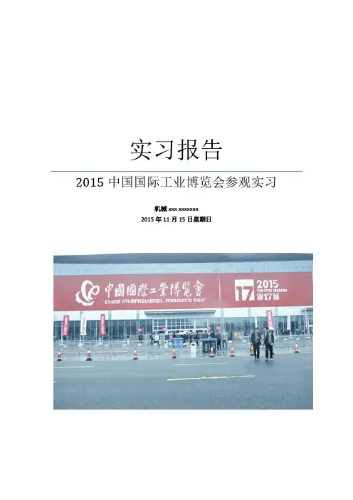
实习报告2015中国国际工业博览会参观实习机械xxx xxxxxxx2015年11月15日星期日2015年11月3日我们班同学在中国国际工业博览会进行了一次参观实习,我认为此次实习的目的有:通过参观工博会以了解机械行业的基本情况,包括涉及领域、主要分类,最新研究成果;观察各个学科的知识内容在具体事物当中的配合与应用;开拓眼界,见识各种奇思妙想,了解机械小至国民生活方方面面,大至国家尖端领域的广泛应用;心存敬畏,在浩如繁星的展品中间,明白自己的渺小与不足,奋发向上,以免坐井观天,同时对机械领域的繁华产生专业自豪感2015中国国际工业博览会(以下简称“中国工博会”)于2015年11月3日-7日在上海国家会展中心举行。
本届中国工博会是由国家工信部、商务部、发改委、科技部、教育部、中国贸促会、中科院和上海市政府共同主办,中国机械工业联合会协办,上海东浩兰生国际服务贸易(集团)有限公司承办的中国最具影响力的国际工业品牌展。
每年十一月在上海举办,迄今已成功举办十七届。
本届工博会规模庞大,以“创新、智能、绿色”为主题,作为展示中国“智”造的重要平台,设有○1数控机床与金属加工--中国最具国际影响力的专业金属加工类展会之一○2工业自动化 --中国乃至亚洲自动化领域最具魅力的专业展会之一○3工业环保技术与设备--关于水处理、节能降耗、循环经济与废弃物处理的国际盛会○4信息与通信技术应用--倡导信息化和工业化融合的国家级信息通信盛会○5新能源与电力电工--面向于电力行业,交易、展示电力、电工、电气技术及设备的国际盛会○6节能与新能源汽车--交易、展示混合动力汽车、电动汽车、燃料电池汽车等新能源汽车、驱动系统、充电设施、相关零部件、汽车设计的国际盛会○7机器人--关于交易、展示机器人全面解决方案、工业机械臂、服务机器人、坐标机器人、工业机器人集成系统的国际盛会○8科技创新--一大批科技部系统、教育部系统和中科院系统及境内外知名企业的优秀创新成果的展示○9航空航天技术--亚太地区最富盛名的航空航天展之一共9大专业展区,吸引了来自中、德、日、美、韩、意、等多个国家和地区共计570家参展企业,其中外商比例超55%,其中,自动化和机器人展区面积是去年的1.5倍,首次新增家用机器人和航空航天展区,展示规模达23万平方米,超过2200家参展商完成折合展位数11226个,比上届增长38.55%,均创下历史新高,展会持续5天。
红邦控制技术4.ABB变频器说明书ACS400ACS500ACS510ACS600ACS800ACS10005.AB变频器说明书1336PLUS IIPowerFlex 4PowerFlex 40PowerFlex400PowerFlex 70PowerFlex 7006.ACTech变频器说明书MC1000QC SCF7.BERGES 变频器说明书ACM-D2/S2/S3ACM-COMPACTSE1SW18.BONFIG LIOLI邦飞利变频器说明书ACT200/400ACU200/400VCB400SYN10S/TSPL200/4009.CT变频器说明书Commander GPUnidriveSPCommander SE10.Drive con变频器说明书XS XT XR VF5100HGVF51RG VFDB VF61C VF6111.EATON 伊顿变频器说明书SVX9000SPX9000MVX900GVX900012.KEB科比变频器说明书F4-S F4-F F5-M F5-M/S13.LG变频器说明书iS3iH3iG5iS5iH14、LUST 路斯特变频器说明书CDD300CDE/CDB3000CDS400015.Moeller金钟-默勒变频器说明书DV6-340DF5116.NORD诺德变频器说明书SK300E SK400E SK5xxE SK530E SK700E SK750E17.PDRIVE变频器说明书18.PE变频器说明书SD100SD250SD450SD70019.RICH利佳/艾瑞克变频器说明书EI-MINI EI-450EI-450M EI-500EI-550EI-600EI-700EI-700120.SEW变频器说明书MOVITRAC-31CMOVIDRIVE-60B/61BMOVITRAC-07MOVIRET-315/328/355/380/315021.SIEI 西威变频器说明书ARTDriveLARTDriveG-EV22.TMT变频器说明书PLUS VTC E IP55PLUSIP55 E23.VACON瓦控变频器说明书NX NXS NXL24.WEG变频器说明书CTW-04CFW-08CFW-09CFW-10CFW-1125.阿尔法ALPHA 变频器说明书ALPHA2000GALPHA2800ALPHA3300MX-eco/pro/multi-eco/multi-pro-1MX-eco/pro/multi-eco/multi-pro-2EV1000EV2000EV3000EV3100EV3500TD900TD1000TD2000 26.艾默生(原华为)变频器说明书APXG3AS ASN MS27.爱得利变频器说明书ADS-A28.爱迪生Adsen变频器说明书29.安邦G9/P9V11G11E11Z9/Z11信AMBITION变频器说明书G5G7E7F7J7V7PC3P5/PC5 30.安川YASKAWA变频器说明书AMP100031.安普(AMPLE)变频器说明书B500B80132.百德福BEDFORD变频器说明书BLDC33.斑科Bantek变频器说明书34.宝德电气BODEBEM100BEM200变频器说明书1011121435.葆德BALDOR变频器说明书36.贝西B&C变频器说明书BC-1000BC-2000BC-230037.传动之星(STAR@DR IVE)变频器说明书SD-5L-G/P/YSD-5L-S SD-7L38.创杰变频器说明书ACT-V6G/P/ZACT-M739.春日(KASUGA)变频器说明书KVFC40.丹佛斯(Danfoss)变频器说明书FC51FC100FC200FC300VLT2000VLT2800VLT2900VLT300041.德弗(DOVOL)变频器说明书DV300DV600ST500HL200042.德莱尔变频器说明书DVA DVM DVS DV100043.德力西变频器说明书CDI900044.德瑞斯(DIRISE)变频器说明书DRS1000-MDRS2000DRS2800DRS300045.东达变频器说明书TDS-F8TDS-V846.东洋(TOYO)变频器说明书VF61R VF6447.东元(TECO)变频器/伺服说明书7300EV7300CV7200MA7200GA7300PA7200GS48.东芝(TOSHIBA)变频器说明书VF-nC1VF-S9VF-S11VF-A5VF-A7VF-AS149.方禾(FangH)变频器说明书TE280F66-B F66-C50.飞兆变频器说明书FG51.佛朗克(FRANCK)变频器说明书FRS2000FRB600052.佛斯特(FIRST)变频器说明书FST-500FST-550FST-60053.富凌(FULING)变频器说明书DZB60J DZB70B DZB200MDZB300B54.富士(FUJI)变频器说明书FRN-G11SFRN-P11SE1S F1S FRN-Mini/C1SFVR-E11S55.高士达(GOLDSTAR)变频器GS200L56.哥伦(GRET)变频器说明书GD-V557.格立特(GREAT)变频器说明书VF10VF11VF1558.海利普变频器说明书HOLIP-A/F/H/MHOLIP-C HOLIP-P59合康亿盛高压变频器说明书HIVERT通用HIVERT矢量60.泓筌变频器说明书HC1-A HC1-M61.鸿宝(HOSSONI )变频器说明书HB-G9/P9HB280-G HB280-P HB280-Z62.华科(HUANIC)变频器说明书HI3G/F HI9G/F63.华蓝(HLinverter)变频器说明书HL200064.汇川(INOVANCE)(默纳克NICE)变频器说明书MD300MD300A MD320MD330ME280NICE300065.汇菱(HUILING)变频器说明书H300066.基创变频器说明书E35067.吉纳变频器说明书MSC-3MFI-Case00/CaseA/CaseB68.加能变频器说明书ACmaster-H7IPC-MD IPC-DR IPC-RF69.佳川(JiaChuan)变频器说明书BP60JCRQ70.佳灵变频器说明书JB6C-T971.金肯(JINKEN)变频器说明书JK-G/P72.九德松益变频器说明书CT-200073.开拓变频器说明书KT-A6G/P74.凯迪华能变频器说明书CD200075.康沃(博世力士乐)变频器说明书S1G2G376.科陆变频器说明书CL1700CL2700CL370077.科姆龙变频器说明书KV1900KV200078.库马克变频器说明书CMK-30079.酷马(QMA)变频器说明书Q7000Q900080.乐邦变频器说明书LB60G LB90G81.乐星产电变频器说明书Starvert82.雷诺尔变频器说明书JJR1000JJR2000JJR500083.力普变频器说明书LP10084.菱科(LINGKE)变频器说明书LK600-G/P/ZSLK80085.隆兴变频器说明书LS200A LS600LS80086.路斯特(LUST)驱动器说明书AD系列CDD系列87.伦茨(Lenze)变频器说明书8200/82108220/824082309300Vector88.麦孚变频器说明书VFD-F540VCD100089.麦格米特变频器说明书MV300MV60090.美之源(MZY)变频器说明书MZY-M/Y/Z/T/ L91.蒙德(MODROL)变频器说明书IMS-GF IMS-GL2IMS-GL392.米高变频器说明书Micovert2003Micovert340N93.明电舍(MEIDEN)变频器说明书VT230S VT230SE VT240S94.南方安华变频器说明书A100E100S10095.能士(NSA)变频器说明书NSA20NSA8096.宁茂(赫力)变频器说明书RM597.欧陆变频器/直流调速器说明书512C590+590P690+590C98.欧姆龙(OMRON)变频器说明书3G3JV3G3EV3G3FV3G3HV3G3MV3G3RV99.欧瑞(HFinverter)(原惠丰)变频器说明书F2000-G F3000F1000-G F1500-G100.派克汉尼汾(parker)变频器说明书AC650AC650V AC690+101.派尼尔(Pioneer)变频器说明书VF2100VF3000VF5000102.普传(POWTRAN )变频器说明书PI97G PI7000/7100PI7500PI7600/7800PI7660103.群倍(QUNBEI)变频器说明书QLP5000104.日搏变频器说明书RB600RB3000RB5000105.日锋(RiFeng)变频器说明书RF200RF9000106.日虹变频器说明书CHRH-A CHRH-C CHRH-D107.日立(HITACHI)变频器说明书SJ100L100SJ200SJ300SJ300-EL L200L300P108.日普(RIPOW)变频器说明书RP3200109.日拓变频器说明书HL3000110.日业(SUNYE)变频器说明书SY3200111.荣信电力电子变频器说明书HVC112.瑞恩(RELIANC E)变频器说明书PSC4000/5000/DDS5000PSC7000VZ3000VZ7000113.赛普(SAPPHIRE)变频器说明书SAP500G SAP300114.赛普变频器说明书SAP900G SAP300V115.三晶变频器说明书SAJ8000116.三肯(SANKEN)变频器说明书SAMCO-i SAMCO-vm05SAMCO-e MF/MS ES/ET/EF IHF/IPF SHF/SPF117.三菱(MITSUBISHI)变频器说明书A500E500F500S500A700E700F700D700118.三木(MIKI)变频器说明书V6119.三品(SANPIN)变频器说明书SKJ SPRQ-333120.三碁(SANCH)(三川)变频器说明书SA SE121.三星(SAMSUNG )变频器说明书MOSCON-E7MOSCON-F7MOSCON-F500122.森兰(SENLAN)变频器说明书SB50SB60/61SB61Z SB70SB100SB200BT40123.山宇变频器说明书SY6000SJR2124.珊星变频器说明书F5000F6000125.深川变频器说明书SVF2000SVF3000126.神源(SYRUNS)变频器说明书SY4000SY5000127.施耐德变频器说明书ATV38ATV58-1ATV58-2ATV61ATV68-1ATV68-2ATV68-3128.时代变频器说明书TVF1000TVF3000TVF5000129.时运捷变频器说明书SuperBona-iF/iPDB-2100130.士林变频器说明书SH系列SS系列SB系列131.世通(EACON)变频器说明书EC1000EC3000EC5000132.收获(Seoho)变频器说明书SOHO-VDSOHO-SMS133.思达(SD)变频器说明书JPSD300 0-G/P/V/H134.斯德博(STOBER)变频器说明书FAS4000FDS4000MDS500SDS4000135.四方变频器说明书C300C320E320E350E380E520H320136.松下(PANASON IC)变频器说明书VF0VF0C VF-8Z VF100DV700/707M1X M2X137.台安(TAIAN)变频器说明书E2N2V2SV300N310S310EV300138.台达(DELTA)变频器说明书VFD-A VFD-B VFD-F VFD-G VFD-M VFD-S VFD-V139.台凌(TAILING)变频器说明书TL80TL100TL100H140.腾龙变频器说明书VG3000-G/H141.天正变频器说明书TVFS9TVFG9/P9TVFG11142.万谷(WANGU)变频器说明书VF2000143.威尔凯变频器说明书WKF WKS WKR500144.威科达变频器说明书V6145.威灵(WELLING )变频器说明书WELLING -G/P/F146.微能变频器说明书WIN-VB WIN-9G WIN-9F WIN-9I WIN-9L147.韦尔变频器说明书AC30G/P /W/H148.伟创(VEICH)变频器说明书AC20AC32AC60AC61-Z AC62-LVSI9000149.沃森(VicRuns)变频器说明书CFC1000CFC4000150.西驰变频器说明书H3000151.西尔康变频器说明书EH600A EH600M EH600W EH600Z152.西林变频器说明书MM410MM420MM430MM4406RA706SE70 153.西门子(SIEMENS)变频器说明书N50N100N300J300154.现代(HYUNDAI)变频器说明书LEI2000LEI2005LEI3000155.晓磊(CHXL)变频器说明书V5/F5156.信捷(XINJE)变频器说明书SD-5L157.星河(XINHE)变频器说明书158.亚泰(YT)变频器说明书YTD-G160.阳冈电子变频器说明书G1/H1/P1E1S1TOPVERTTOPVERTS1TOPVERTE1161.依尔通(Emotron)变频器说明书FDU VFX VSA VSC CDX CDU MSF162.依托(ESTAR)变频器说明书EG/EF163.亿森变频器说明书参数表164.易能变频器说明书EDS700EDS2860165.易驱变频器说明书ED2003ED2800ED3000ED300S ED3100166.意科(IECCO)变频器说明书SINUS-N167.英泰(Inverte k DRIVES)变频器说明书OptidrivePlus3GVOptidrivePlus3GVCompactOptidriveVTCOptidriveEOptidriveE1OptidriveE2OptidriveMEMA4X168.英威腾(INVT)变频器说明书CHV100CHV190CHF100169.鹰垦(INK)变频器说明书SLX170.优利康变频器说明书YD3000YD5000171.尤尼康(UNICON)(原北京兰海)变频器说明书低速大扭矩无码盘有码盘172.誉强(YUQIANG )变频器说明书YQ3000-MYQ3000-AYQ3000-G173.远川(YCDZ)变频器说明书YC-G YC-P174.正频(JPS)变频器说明书PDS PDA/H/E175.正泰(CHINT)变频器说明书NI01176.正弦(SINEE)变频器说明书SINE300SINE303SINE307SINE308SINE309177.正阳(Zhengya ng)变频器说明书ZY29/31/98ZY-812178.中源(ZYDL)变频器说明书ZY-G800ZY-G800EZY-A900ZY-P800179.中远变频器说明书MF6MF5/20MF30180.珠峰变频器说明书DLT-G11/P11 /Z11/ZK181.住友(SUMITOMO)变频器说明书HF320SF320HF430182.紫日(CHZIRI)变频器说明书ZVF7ZVF9ZVF9V ZVF11183.南海华腾(V-T)变频器说明书V5-H E5-P V6-HVF64VFK1/VFVFN2N1EI-8001EI SuperNTD3000TD3100TD3200TD3300VLT5000。
写字楼旋转门招标技术规格书供应商所投产品的主要部件为进口产品,必须提供进口报关单及原产地证明。
质量和技术要求(一)旋转门生产厂家必须通过ISO9001质量认证。
(二)门体结构:A.旋转门采用铝合金框架结构,国际6063-T6系列B.华盖厚度不低于10mm,立柱不低于8mm,使门体更加牢固、稳定。
C.外饰面采用深咖啡色氟碳喷涂饰面。
D.玻璃:弧形侧墙采用(5+0.76pvb+5)mm安全夹胶玻璃结构,中间门页采用6mm钢化玻璃。
(三)控制系统:A.控制箱:采用进口主板或控制器,对感应器和安全装置的信号进行处理,同时控制转速、平移、照明等功能。
B.安全装置:入口必须具备接触式和非接触式防夹装置,旋转门页具备非接触式防撞装置,立柱上设有急停按钮和残疾人按钮,并且要求是进口知名品牌。
(四)驱动系统:进口变频马达,双驱动。
(五)具有以下运行方式:A.自动旋转方式1:当有行人通过触发红外线移动探测器输入时,旋转门门页由准备位置开始以快速旋转(大约每分钟3~4 转),当行人离开探测区域后,门页自动降至慢速(为正常速度的一半)至准备位置停止旋转,等待下一次感应器输入。
B.自动旋转方式2:旋转门门页以慢速(为正常速度的一半)常转不停,当有行人通过触发红外线移动探测器输入时,门页以快速(大约每分钟3~4 转)开始旋转。
当行人离开探测区域后,门页自动降至慢速(为正常速度的一半)转不停,此时天花灯常亮。
C.自动感应门通行:门页以慢速旋转至中轴位置后停止旋转,中间自动感应门开始工作,感应门的开启由红外线移动探测器控制。
D.自动感应门常开:中间自动感应门自动开启到全开启位置,天花灯常亮。
E.关闭上锁:旋转门门页以慢速旋转,旋转至上锁位置时门页停止旋转,电子机械锁上锁。
(六)外观尺寸:(详见CAD图)旋转门内直径:4200mm旋转门全高:3000mm(七)旋转门具备以下功能:1、自由调速2、防撞功能3、高、低速运行方式4、照明系统5、消防报警联动功能:将大厦的火警信号线接入旋转门内的消防联动端子,当大厦发生火灾,旋转门收到火警信号,无论处于何种状态,都会自动切换到平移门常开状态,方便混乱的行人紧急疏散。
PLC通讯类:三菱:1、三菱232/485BD通信问题问题描述:用三菱485BD和触摸屏无法进行通信。
解决思路:1、检查通信参数设置正确。
2、在下载PLC程序时,客户没有将“参数”选项勾选,勾选“参数”下载PLC程序后,通信正常。
注意:三菱PLC通讯参数修改后,在下载时一定要选中“参数”项,把设定好的参数设定到PLC,并重新上电,让新设定的参数生效。
2、某客户设备上配备的是三菱A3A型号的PLC要与MT6100i的触摸屏通讯,但是一直出现通讯不上的情况解决思路:1、检查触摸屏上的参数设置,发现参数设置没有问题;2、将原A3N/A1SH驱动修改为A2A驱动重新测试,确定通讯正常。
3、FX3G如何连接四台HMI解决思路:1、使用MT8000系列HMI,第一台HMI使用串口与PLC通讯;2、主屏使用以太网接交换机,其余从屏接在交换机上,进行测试;系统测试通讯成功。
3、在设备列表内添加远端PLC,IP地址设置为主屏的IP地址,从屏HMI设置如下图所示,系统连接图如下:4、TK6070iH与三菱PLC通讯问题问题描述:使用TK6070iH与三菱PLC无法建立通讯。
解决思路:1、检查参数设置和通讯线,没有问题;2、检查客户程序,发现勾选了系统参数内的工程档案保护,取消工程档案保护后,通讯正常。
注意:人机识别码地址为LW9046-LW9047;当勾选了工程档案保护时,该值必须与EB8000中设定工程档案识别码一致方可通讯;可以用LB9046显示状态,当LB9046为ON时表示识别码错误。
5、触摸屏与Q02无法通讯的问题解决思路:1、WEINVIEW HMI与三菱Q02PLC连接针脚图如下,使用错误的通讯线有可能会导致PLC通讯死机。
路由器HMI1PLCHMI2IP:192.168.1.20IP:192.168.1.10HMI3IP:192.168.1.21HMI4IP:192.168.1.222、与Q02串口通讯,必须让HMI10秒钟去初始化Q02驱动,这个过程中HMI不能向PLC发送数据,否则会导致PLC通讯“死机”。
Information for the operator of the machine/systemEDK82MVXXX !N;,Global Drive 8200motecFrequency inverter0.25...7.5kWÄ!N ;,äThis documentation applies to8200motec inverters as of versionE82MV xxx_x B001XX Vx2xTypePower(e.g.551=55×101W=0,55kW)(e.g.752=75×102W=7,5kW)Voltage class2=230V4=400V/500VHardware versionSoftware versionã2002Lenze AGThis documentation contains all information the machine operator require in orderto operate the drive controller of the8200motec series installed in yourmachine/system.If you do not change the content,you are allowed to use the information in thisdocumentation for your purposes without contacting Lenze.The information necessary for the project planning of a machine/system can be found inthe Mounting Instructions and Operating Instructions for the8200motec frequencyinverters.The Mounting Instructions are included in the scope of delivery,the OperatingInstructions can be ordered at your Lenze representative.The downloading of the Lenze documentation can be made in the internet as an AdobeAcrobat file:http://www.lenze.de1.003/2002TD14Safety informationLenzecontrollers3lEDK82MVXXX EN 1.01Safety information1.1General safety and application notes for Lenze controllers(according to Low-Voltage Directive 73/23/EEC)1.GeneralLenze controllers (frequency inverters,servo inverters,DC controllers)can carry a voltage or parts of the controllers can rotate during operation.Surfaces can be hot.If the required cover is removed,the controllers are used inappropriately or installed or operated incorrectly,severe damage to persons or material assets can occur.For more information please see the documentation.All operations concerning transport,installation,and commissioning as well as maintenance must be carried out by qualified,skilled personnel (IEC 364and CENELEC HD 384or DIN VDE 0100and IEC report 664or DIN VDE 0110and national regulations for the prevention of accidents must be observed).According to this basic safety information qualified,skilled personnel are persons who are familiar with the assembly,installation,commissioning,and operation of the product and who have the qualifications necessary for their occupation.2.Intended useDrive controllers are components which are designed for the installation into electrical systems or machinery.They are not to be used as domestic appliances,but only for industrial purposes according to EN 61000-3-2.The documentation contains information about the compliance of the limit values with EN 61000-3-2.When installing controllers into machines,commissioning of the drive controllers (i.e.the starting of operation as directed)is prohibited until it is proven that the machine corresponds to the regulations of the EC Directive 98/37/EG (Machinery Directive);EN 60204(VDE 0113)must be observed.Commissioning (i.e.starting of operation as directed)is only allowed when there is compliance with the EMC Directive (89/336/EEC).The drive controllers meet the requirements of the Low-Voltage Directive 73/23/EEC.The harmonised standards EN 50178/DIN VDE 0160apply to the controllers.The technical data as well as the connection conditions can be obtained from the nameplate and the documentation.The instructions given must be strictly observed.Warning:Controllers are products with restricted availability according to EN 61800-3.These products can cause interferences in residential premises.If controllers are used in residential premises,corresponding measures are required.3.Transport,storageThe notes on transport,storage and appropriate handling must be observed.Climatic conditions according to EN 50178apply.4.InstallationThe controllers must be installed and cooled according to the regulations given in the corresponding Instructions.Ensure careful handling and avoid mechanical overload.Do not bend any components and do not change the insulation distances during transport and storage.Electronic components and contacts must not be touched.Controllers contain electrostatically sensitive components which can easily be damaged by inappropriate handling.Do not damage or destroy any electrical components since this could mean hazards for your health!5.Electrical connectionWhen working on live controllers,the valid national regulations for the prevention of accidents (e.g.VBG 4)must be observed.The electrical installation must be carried out in compliance with the corresponding regulations (e.g.cable cross-sections,fuses,PE connection).Additional notes and information can be obtained from the corresponding Instructions.The Instructions contain notes concerning wiring according to EMC regulations (shielding,earthing,filters and cable routing).These notes must also be observed when using CE-marked controllers.The compliance with limit values required by the EMC legislation is the responsibility of the manufacturer of the machine or system.6.OperationIf necessary,systems including controllers must be equipped with additional monitoring and protection devices according to the applying safety regulations (e.g.regulation for technical equipment,regulation for the prevention of accidents).The controller can be adapted to your application.Please observe the corresponding information given in the Instructions.After a controller has been disconnected from the voltage supply,all live components and power connections must not be touched immediately because capacitors can still be charged.Please observe the corresponding stickers on the controller.All protection covers and doors must be shut during operation.Note for UL-approved systems with integrated controllers:UL warnings are notes which only apply to UL systems.The Instructions give UL-related information.7.Safe standstillThe variant V004of 9300and 9300vector,the variant Bx4x of 8200vector controller and the axis controller ECSXA064support the function ”Safe standstill”,protection against unexpected start,according to the requirements of Annex I No.1.2.7of the EC Directive ”Machinery”98/37/EG,DIN EN 954-1category 3and DIN EN 1037.Please observe the notes on the function ”Safe standstill”given in the corresponding Instructions.8.Maintenance and servicePlease observe the Instructions given by the manufacturer.Please observe the product-specific safety and application notes in these Instructions.Safety informationLenze low-voltagemachinery4lEDK82MVXXX EN 1.01.2General safety and application notes for Lenze low-voltage machinery(in conformity with the Low-Voltage Directive 73/23/EEC)1.GeneralLow-voltage machines have dangerous,live and rotating parts as well as possibly hot surfaces.All operations serving transport,connection,commissioning and maintenance are to be carried out by skilled,responsible technical personnel (observe EN 50110-1(VDE 0105-100);IEC 60364).Improper handling cancause severe injuries or damages.Synchronous machines induce voltages at open terminals during operation.2.Application as directedThese low-voltage machines are intended for industrial and commercial installations.They comply with the harmonized standards of the series EN 60034(VDE O53O).Their use in hazardous areas is prohibited unless they are expressly intended for such use (follow additional instructions).The enclosures ≤IP23are by no means intended for outdoor use.Air-cooled designs are rated for ambient temperatures between -15°C and -10°C and +40°C and altitudes ≤1000m a.m.s.l.,from -20°C to +40°C without brake or with spring-operated brake,with separate ventilation or self ventilation,from -15°C to +40°C with permanent magnet brake and from -10°C to +40°C with separate fan.Check indications on the nameplate and if they are different,observe them.The conditions on site must correspond to all nameplate data.Low-voltage machines are components for the installation into machines as defined in the Machinery Directive 98/37/missioning is prohibited until the conformity of the end product with this Directive has been established (follow a.o.EN 60204-1).The integrated brakes cannot be used as safety brakes.It cannot be ruled out that factors which cannot be influenced,such as oil ingression because of a defective A-side shaft seal,cause a torque reduction.3.Transport,storageThe forwarder must be informed directly after receipt of the goods about all damages or deficiencies;if necessary,commissioning must be stopped.Tighten screwed-in ring bolts before transport.They are designed for the weight of the low-voltage machine,do not apply extra loads.If necessary,use suitable and adequately dimensioned means of transport (e.g.rope guides).Remove the shipping brace before commissioning.Reuse it for further transports.For storage of low-voltage machines ensure a dry,dust-free and low-vibration (v rms ≤0.2mm/s)environment (danger of bearing damage at rest).Measure the insulation resistance before commissioning.If the values are ≤1k Ωper volt of rated voltage,dry the winding.4.InstallationEnsure an even surface,solid foot or flange mounting and exact alignment if a direct clutch is connected.Avoid resonances with the rotational frequency and double mains frequency which may be caused by the assembly.Turn rotor by hand,listen for unusual slipping noises.Check the direction of rotation when the clutch is not active (observe section 5).Use appropriate tools to mount or remove belt pulleys and clutches (heat generation!)and cover them with a touch guard.Impermissible belt tensions must be avoided (technical list).The machines are half-key balanced.The clutch must be half-key balanced,too.The visibly protruding part of the key must be removed.If required,provide pipe connections.Mounting positions with shaft end at top must be protected with a cover which avoids the ingression of foreign particles into the fan.Free circulation of the cooling air must be ensured.The exhaust air -also the exhaust air of other machines next to the drive system -must not be immediately taken in again.5.Electrical connectionAll operations must be carried out only by qualified and skilled personnel when the low-voltage machine is at standstill and when the machine is de-energized and protected against unintentional restart.This also applies to auxiliary circuits (e.g.brake,encoder,separate fan).Check safe isolation from the supply!If the tolerances in EN 60034-1;IEC 34(VDE 0530-1)-voltage ±5%,frequency ±2%,waveform,symmetry -are exceeded,more heat will be generated and the electromagnetic compatibility will be influenced.Observe the indications on the nameplate,operating notes,and the connection diagram in the terminal box.The connection must ensure a continuous and safe electrical supply (no loose wire ends);use appropriate cable terminals.The connection to the PE conductor must be safe.The plug-in connector must be screwed up tightly (to stop).The clearances between bare,live parts and earth must not fall below:8mm at V rated ≤550V,10mm at V rated ≤725V,14mm at V rated ≤1000V.The terminal box must be clean and dry;foreign particles,dirt and moisture affect operation.All unused cable entries and the box itself must be sealed against dust and water.For the trial run without output elements,lock the key.Check brake operation before the commissioning of low-voltage machines with brakes.6.OperationVibration severities v rms ≤3.5mm/s (P rated ≤15kW)or 4.5mm/s (P rated >15kW)are acceptable when the clutch is activated.If deviations from normal operation occur,e.g.increased temperature,noise,vibration,find the cause and,if necessary,contact the manufacturer.Switch-off the machine in problematic situations.If the drive is exposed to dirt,clean it regularly.Do not switch-off the protection devices,not even for trial runs.Integrated temperature sensors do not provide full protection.If necessary,limit the maximum current.Connect the function blocks to the option switch-off after several seconds of operation at I >I rated ,especially if blocking may occur.Shaft seals and bearings have a limited service life.Regrease the bearings using the relubrication facility while the low-voltage machine is running.Observe the saponification number.If the grease drain hole is sealed with a plug (IP54drive end;IP23drive end and non-drive end),remove the plug before commissioning.Seal the bore holes with grease.Replace the prelubricated bearings (2Z-bearings)after approx.10.000h -20.000h,at the latest however after 3-4years.Observe the manufacturer’s instructions.Safety informationResidual hazards,Layout of the safetyinstructions5lEDK82MVXXX EN 1.01.3Residual hazardsProtection of persons•Before working on the motec or opening the housing,check that no voltage is applied.Wait for at least 3minutes,since after mains switch-offthe power terminals U,V,W;BR0,BR1,BR2andthe pins of the FIF interface remain live.–After you have opened the motec check whether the power terminals L1,L2,L3;U,V,W;BR0,BR1,BR2,relay outputs K11,K12,K14and pins of the FIF interface are not live any more.–Even if the motec is separated from the mains,the relay outputs K11,K12,K14can remain live!•If you use the not fail-safe function “Selection of direction of rotation”via the digital signal DCTRL1-CW/CCW (C0007=-0-...-13-,C0410/3≠255):–In the event of an open circuit or failure of the control voltage,the drive can change its direction of rotation.•If you use the function ”Flying-restart circuit”(C0142=-2-,-3-)with machines with a low moment of inertia and a minimum friction:–After controller enable in standstill,the motor can start for a short time or change its direction of rotation for a short time.•The motec heatsink temperature is >60°C:–Direct skin contact with the heatsink results in burnings.Controller protection•8200motec 3...7,5kW (E82MV302_4B,E82MV402_4B,E82MV552_4B,E82MV752_4B):–Cyclic connection and disconnection of the controller supply voltage atL1,L2,L3canexceed and destroy the input current limit!–In case of cyclic mains switching over a longer period of time three minutes have to pass between two starting operations!•Depending on the controller settings,the connected motor can be overheated:–at,for instance,longer DC-braking operations.–at longer operation of self-ventilated motors at low speed.Overspeeds •Drives can reach dangerous overspeeds (e.g.setting of inappropriately high field frequencies):–The controllers do not offer any protection against these operating conditions.For this,use additional components.1.4Layout of the safety informationAll safety information given in these Operating Instructions have the same layout:Signal word (characterises the severity of danger)Note (describes the danger and gives information how to avoid it)Parameter settingParameter setting using thekeypad6lEDK82MVXXX EN 1.02Parameter setting2.1Parameter setting using the keypadThe keypad is available as accessory.A full description can be obtained from the information included in the keypad delivery.2.1.1Menu structureAll parameters for controller setting or monitoring are saved in codes under the menus User and all .The codes have numbers 6and are abbreviated in the text with a ”C”before the number.Some codes store the parameters in numerical “subcodes”7to ensure that parameter setting is clearly structured (example:C0517menu User ).•The menu User–is active after every mains switching or keypad attachment during operation.–contains all codes for a standard application with linear V/f characteristic control (Lenze setting).–can be modified as required under C0517.•The menu all–contains all codes.–shows a list of all codes in ascending order.•The change between User and all and how to change parameters in the codes is describedon the following pages.Parameter settingParameter setting using thekeypad7lEDK82MVXXX EN 1.02.1.2The menu U s e r -The 10most important drive parametersAfter mains switching or plugging in the keypad during operation,the 10codes defined to be the most important in the user menu User (Code C0517)are available immediately.In default setting the menu contains User all codes required for a standard application with linear V/f characteristic control.CodeNameLenze settingC0050Output frequencyDisplay:Output frequency without slip compensation selection -0-Standard I/OX3/8:0...5V /0...10V /0...20mAC0034Setpoint range0Application I/OX3/1U:0...5V /0 (10V)X3/2U:0...5V /0 (10V)-0-E4E3E2E1C0007Fixed configuration of digital inputsCW/CCW DCB JOG2/3JOG1/3CW/CCW rotation DC-injection brakeSelection of fixed setpoints C0010Minimum output frequency 0.00Hz C0011Maximum output frequency 50.00Hz C0012Acceleration time main setpoint 5.00sec C0013Deceleration time main setpoint 5.00sec C0015V/f rated frequency 50.00HzC0016U min boostdepending on the inverter type C0002Parameter set transfer/reset see code tableTip!Use C0002”Parameter set transfer”to easily transfer configurations from one controller to the other or to reset the controller to Lenze settings.Parameter settingParameter setting using thekeypad8lEDK82MVXXX EN 1.02.1.3Change between the menus U S E r and A L L2.1.4Parameter change in menusStep KeysDisplayNoteExample1.Controller inhibit s dc Only necessary if you want to change codes marked with “[]”in the code table,e.g.[C0002].All other parameters can be changed during operation.2.Set parameters wx fReduce C00123.pz XXXX Select code0012(acceleration time)500100s4.x k 001For codes without subcodes:Jump to i (and then 6.)from5.00s to 1.005.yz XXX Select subcode6.x i 5.00s7.yz XXXXX Set parameters1.00s8.v STOreAcknowledge entry if p blinkingwAcknowledge entry if p is not blinking;v is not active 9.Restart the ”loop”at 2.to set other parameters.广州科沃—工控维修的120 www.gzkowo.comTroubleshooting and fault eliminationMaloperation of thedrive9lEDK82MVXXX EN 1.03Troubleshooting and fault elimination3.1Maloperation of the driveFaultCauseRemedyMotor does not rotateDC-bus voltage too low(Red LED is blinking every 0.4s;keypad display LU )Check mains voltageController inhibited(Green LED is blinking,keypad display:c )Remove the controller inhibit,controller inhibit can be set through several sources Automatic start inhibited (C0142=0or 2)LOW-HIGH edge at X3/28If necessary,correct start condition (C0142)DC injection brake active (DCB)Deactivate DC-injection brakeMechanical motor brake is not releasedManual or electrical release of mechanical motor brake Quick stop (QSP)active (keypad display:c )Remove quick stop Setpoint =0Setpoint selectionJOG setpoint activated and JOG frequency =0JOG setpoint selection (C0037...C0039)Active faultEliminate faultWrong parameter set activeChange to correct parameter set via terminal Control mode C0014=-4-,-5-,but no motor parameter identificationMotor parameter identification (C0148)Under C0410several functions,which exclude each other,are assigned to the same signal source.Correct configuration in C0410Use internal voltage source X3/20for function modules Standard-I/O,INTERBUS,PROFIBUS-DP or LECOM-B (RS485):Bridge between X3/7and X3/39is missingJumper terminalsdoes not Defective motor cableCheck motor cableMotor Maximum current too low (C0022,C0023)Adaptation to applicationrotate smoothly Motor underexcited or overexcitedCheck parameter setting (C0015,C0016,C0014)C0084,C0087,C0088,C0089,C0090,C0091and/or C0092are not adapted to the motor dataManual adaptation or identification of motor parameters (C0148)Setting of C0016too high Correct setting Current Setting of C0015too lowCorrect settingconsumption of motor too high C0084,C0087,C0088,C0089,C0090,C0091and/or C0092are not adapted tothe motor dataManual adaptation or identification of motor parameters (C0148)Motor rotates,setpoints are “0”With the function j of the keypad a setpoint has been selected.Set the setpoint to ”0”by C0140=0Motor parameter Motor too small compared with rated power identificationstops with error LP1DC brake active via terminal Unacceptable drive response with vector controlvarious Vector control optimisationTroubleshooting and fault eliminationErrormessages10lEDK82MVXXX EN 1.03.2LEDs at the controller (operating status display)LED Operating statusgreen red on off Controller enabledonon Mains switched on and automatic start inhibited blinking offController inhibitedoff blinking every second Fault active,check under C0161offblinking every 0.4seconds Undervoltage switch-offfast blinkingoffMotor parameter identification3.3Fault messages at the keypad or in the parameter setting program Global Drive ControlDisplayFaultCause Remedy Keypad PC 1)noer0No fault --ccr71System faultStrong interferences on control cables Shield control cablesa y Ground or earth loops in the wiringce0a 61Communication error to AIF Transmission of control commands via AIF is interferedPlug the communication module firmly into the hand terminalce1a 62Communciation error at CAN-IN1with sync control CAN-IN1object receives faulty data or communication interrupted•Plug-in connection for bus module óCheck FIF •Check transmitter•Increase monitoring time under C0357/1if necessary ce2a 63Communication error to CAN-IN2CAN-IN2object receives faulty data or communication is interrupted •Plug-in connection for bus module óCheck FIF •Check transmitter•Increase monitoring time under C0357/2if necessary ce3a 64Communication error to CAN-IN1with event or time controlCAN-IN1object receives faulty data or communication interrupted •Plug-in connection for bus module óCheck FIF •Check transmitter•Increase monitoring time under C0357/3if necessary ce4a 65BUS-OFF(many communication errors occurred)Controller has received too many faulty telegrams via system bus and has been disconnected from the bus •Check whether the bus terminator is available •Check screen contact of the cables •Check PE connection•Check the bus load,if necessary,reduce the baud rate ce5a66CAN Time-OutWith remote parameter setting via system bus (C0370):Slave does not munication monitoring time exceeded•Check wiring of the system bus •Check system bus configurationOperation with module on FIF:Internal errorContact Lenze ce6a 67Function module system bus (CAN)is set to ”Warning”or ”BUS-OFF”(only generated if C0128=1)CAN controller sends ”Warning”or ”BUS-OFF”•Check whether the bus is terminated•Check screen contact of the cables •Check PE connection•Check the bus load,if necessary,reduce the baud rate EEr a 91External error (TRIP-SET)A digital signal used for the function TRIP set has been activated.Check external encoder H05a 105Internal faultContact Lenzeid1a 140Faulty parameter identification Motor not connectedConnect motorLP1a 32Error in motor phase(only generated if C0597=1)•Failure of one/several motor phase(s)•Motor current too low•Check motor cables•V boost C t t ith di d tLP1182Error in motor phase(only generated if C0597=2)min •Connect motor with corresponding power or adapt motor under C0599LU 1030DC-bus undervoltage Mains voltage too low Check mains voltage cgDC-bus voltage too lowCheck supply module400V controller connected to 240V mainsConnect the controller to the appropriate mains voltageTroubleshooting and fault eliminationErrormessages11lEDK82MVXXX EN 1.0Display RemedyCauseFault Keypad PC 1)OC111short-circuit short-circuit•Find reason for short circuit;check motor cables •Check brake resistora Excessive capacitive charging current of the motor cableUse shorter/low-capacity motor cables OC212Earth faultGrounded motor phaseCheck motor,check motor cableaExcessive capacitive charging current of the motor cableUse shorter/low-capacity motor cablesEarth fault detection can be deactivated for checking OC313Overload inverter during acceleration or short circuitAcceleration time (C0012)too short •Increase acceleration time •Check drive selection aDefective motor cable Check wiring Interturn fault in the motorCheck motorOC4a 14Overload controller during deceleration Deceleration time too short (C0013)•Allow longer deceleration time•Check the external brake resistor selection OC5a 15Controller overload in stationary operationLong and frequent overload periodsCheck drive selection16Motor overload (I 2x t overload)Motor thermally overloaded by for instanceOC6a ()•impermissible continuous current•Check drive selection•frequent or too long acceleration processes•Check setting under C0120OH a 50Heatsink temperature >+85°CAmbient temperature T amb >+60°C •Allow controller to cool down and ensure betterventilation•Check ambient temperatureOH -Heatsink temperature >+80Heat sink very dirtyClean heat sinke p °CImpermissible high current or frequent and long acceleration processes•Check drive selection•Check load,if necessary replace sluggish,defective bearingsOH353PTC monitoring (TRIP)(only generated if C0119=1Motor too hot because of impermissibly high current or frequent and long acceleration processes Check drive selection a (y g or 4)PTC not connected Connect PTC or switch-off monitoring (C0585=3)OH4a 54Controller overtemperatureController inside too hot•Reduce controller load •Improve cooling•Check fan in the controller OH51203PTC monitoring (only generated if C0119=2)Motor too hot because of impermissibly highcurrent or frequent and long acceleration processes Check drive selection(y g or 5)PTC not connected Connect PTC or switch-off monitoring (C0585=3)OU 1020DC-bus overvoltage Mains voltage too high Check voltage supplycgBraking operation•Prolong deceleration times.•For operation with external brake resistor:–Check dimensioning,supply and connection of brake resistor–Increase the deceleration timesEarth leakage on the motor sideCheck motor cable and motor for earth fault (disconnect motor from inverter)Pr a 75Faulty parameter transfer when using the keypadAll parameter sets are faulty It is absolutely necessary to repeat the data transfer or load the factory setting before the controller is enabled.Pr1a 72Faulty transmission of PAR1when using the keypad PAR1is faulty.Pr2a 73Faulty transmission of PAR2when using the keypad PAR2is faulty.Pr3a 77Faulty transmission of PAR3when using the keypad PAR3is faulty.Pr4a 78Faulty transmission of PAR4when using the keypad PAR4is faulty.Pr5a 79Internal faultContact LenzePt5a81Time error during parameter set transferData flow interrupted by keypad or PC,e.g.keypad disconnected during data transmission.It is absolutely necessary to repeat the data transfer or load the factory setting before the controller is enabled.。
济和科学的角度,深入探讨怎样才能使中欧工业到2030年仍能保持一个成功的全球生产基的地位。
到2030年,互联网和其他服务联网的系统将使所有行业实现智能化,并取代传统的机械和机电一体化产品服务。
本书每个章节都从非常特殊的角度表达了对工业4.0的独特看法,所有这些观点综合在一起可以为我们清淅地勾勒出目前工业产业发展所处岔路口的情形。
书????名工业4.0又????名工业4.0:即将来袭的第四次工业革命作????者乌尔里希·森德勒/主编原版名称Industrie 4.0译????者邓敏李现民ISBN类????别经济管理页????数197页定????价45.00元出版社机械工业出版社出版时间2014年7月装????帧平装开????本16开目录1名人评价2作者简介3目录4前言5精彩书摘?软件:工业的未来“工业4.0”是德国联邦教研部与联邦经济技术部在2013年汉诺威工业博览会上提出的概念。
它描绘了制造业的未来愿景,提出继蒸汽机的应用、规模化生产和电子信息技术等三次工业革命后,人类将迎来以信息物理融合系统(CPS)为基础,以生产高度数字化、网络化、机器自组织为标志的第四次工业革命。
“工业 4.0”概念在欧洲乃至全球工业业务领域都引起了极大的关注和认同。
西门子作为德国最具代表性的工业企业以及全球工业业务领域的创新先驱,也是“工业 4.0”概念的积从2006年起,鲁思沃成为了西门子医疗系统集团执行管理层的一员。
2008年,他进入西门子股份公司管理委员会,成为领导公司人力资源部门,劳动董事及欧洲、非洲和中东地区分公司负责人的主管。
2010年,鲁思沃接管了工业部的领导工作和对企业信息化和企业供应链管理中央机构的监督工作。
乌尔里希森德勒(Ulrich Sendler),生于1951年,毕业于克雷菲尔德市恩斯特莫里茨阿恩特人文中学。
在经过奥迪公司内卡苏尔姆工厂的模具制造人员培训和位于海尔布隆市的德劳茨模具制造公司的数控编程人员培训之后,进入海尔布隆大学学习精密仪器工程学,并于1985年获得硕士学位。