(4)丹麦格林GREEN仪表性能优势介绍
- 格式:pdf
- 大小:128.30 KB
- 文档页数:3

林格曼黑度计/测烟望远镜
JCP-LGM型(原P-LGM)
一、产品概述:
聚创JCP-LGM型林格曼黑度计是利用林格曼烟气浓度图测量烟气黑度等级的仪器。
它把各国通用的标准林格曼烟气浓度图缩制在一块玻璃上,将其与从望远镜上观测到的实际烟气相对比,从而确定烟气的黑度等级。
其最大的特点就是可以将数码照相机固定在仪器上拍照以记录观测结果。
它具有测试快速、简单、准备度高等特点,可广泛应用于各地的环境保护部门和各工矿企业的烟气黑度测定。
二、产品特点:
1测量距离远
2清晰度高,准确度高
3数码相机万用接口支架,便与拍照,可将结果记录下来
4仪器使用简单方便,一般工作人员即可操作
5配套国家检测部门出具的检测证书
三、技术参数:
望远镜视角放大率:15倍
望远镜观测距离:10~2000米
物镜通光孔径:80毫米
林格曼黑度等级:0~5级
分划面摄像倍率:2倍
外型尺寸:(600×105×105)mm 四、产品效果:
(聚创环保提供)。

实测:GREENL格林尔滤镜UV镜L39对紫外线的阻挡效果
UV镜又叫做紫外线滤光镜,即Ultra Violet。
通常为无色透明的,不过有些因为加了增透膜的关系,在某些角度下观看会呈现紫色或紫红色。
许多人购买UV镜来保护娇贵的镜头镀膜,其实这仅仅是它的一项附属功能。
UV镜的主要功能是用于吸收波长在400毫微米以下的紫外线,而对其他可见/不可见光线均无过滤作用。
它之所以能够过滤紫外线是因为镜片中含有铅,因此UV镜与其它相同尺寸和厚度的镜片相比要重一些。
UV镜适用于海边、山地、雪原和空旷地带等环境下的拍摄,能减弱因紫外线引起的蓝色调。
同时对于数码相机来说,还可以排除紫外线对CCD的干扰,有助于提高清晰度和色彩还原的效果。
在选购UV镜时,需要注意的是镜头不要偏色,并且相机安装该滤镜后,广角端尤其是长焦端都能对焦清晰。
此外,如果仅仅为了保护相机镜头不受伤害,还可以选购专门的镜头保护镜来代替UV镜。
由于镜头保护镜采用多层镀膜技术,透光率要远远好于大多数UV镜,因而能够完全保留原镜头的特性。
以上视频,我们使用验钞机的紫外线灯和L39的合系列UV 镜做测试GREENL格林尔合系列L39UV滤镜,能完全阻挡
L390波长的紫外线的同时,有效保留了可见光,使照片色彩丰富,提升拍摄清晰度!。

格林威尔指示灯含义:(我们用的都是MSAP-E120S)电源指示灯 (PWR) 正常工作时绿色常亮运行指示灯 (RUN) 绿灯均速闪烁,表示CPU正常运行。
总告警指示灯 (ALM) 当本端设备光接口,E1接口有任何告警时,此红灯常亮。
对端告警指示灯 RAI(M) 当对端设备光接口,E1接口有任何告警时,此红灯常亮。
收无光告警指示灯 (NOP) 由于对端设备故障或光纤断裂造成无光信号输入时,此红灯亮。
失步告警指示灯 (LOF) 当发生光口帧失步失,此红灯亮。
光口IE-3误码告警指示灯 (IE-3) 当光口有10-3误码告警时,此红灯亮。
光口IE-6误码告警指示灯 (IE-6) 当光口有10-6误码告警时,此红灯亮。
E1测试指示灯 E1T 当进行E1支路误码测试时,红灯闪烁;在测试过程中,如果出现误码,此灯亮。
停止测试后,此灯灭。
未进行误码测试时,红灯灭。
V35上联E1帧丢失告警(AIS/LOF)有AIS告警时,常亮。
有LOF告警时,闪亮。
没有告警时,此灯灭。
格林威尔前面板按键开关说明告警音屏蔽按键(ALARM/MUTE)未按下时,有声音告警(默认)按下时,有告警时,不发出声音。
E1告警屏蔽按键(UNMASK/MASK) 未按下时,E1支路告警状态都会显示。
按下时,当前未使用的E1告警被屏蔽,正在使用的E1支路输入故障,告警不受影响。
本/对端告警选择按键(LOCAL/REMOT) 未按下时,NOP,LOF,IE-3,IE-6,E1 ALM(1-4)告警指示灯显示为本端设备告警状态。
(默认)按下时,告警指示灯显示为对端设备告警状态。
格林威尔背后拨码开关说明E1LOOP(SW1-1)E1环回本对端选择,OFF 本端(默认); ON 远端。
(SW1-2~SW1-5)第一至第四路E1自环,OFF 不自环(默认); ON 自环。
E1TEST(SW1-6)E1误码测试使能;OFF 不测试(默认); ON 测试。
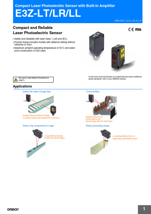
For the most recent information on models that have been certified for safety standards, refer to your OMRON website.ApplicationsGreatly Enhanced Beam Visibilityfor Easier Optical Axis Adjustment of SensorsDetect the sides of large tiles.Detect chip components on tape.Long-distance Sensingat 300 mm (White Paper)Small Objects andNarrow Gaps with the Small SpotCount bottles.Detect protruding straws.A Low Black/White Error for Applications with Mixed ColorsCompact and ReliableLaser Photoelectric Sensor•Safety and reliability with laser class 1 (JIS and IEC).•Product lineup includes models with distance setting without influence of color.•Maximum ambient operating temperature of 55°C and water-proof construction in E3Z class.Be sure to read Safety Precautions on page 9.E3Z-LT/LR/LLOrdering InformationSensors (Refer to Dimensions on page 11.)*2.Values in parentheses indicate the minimum required distance between the Sensor and Reflector.AccessoriesSlits (A Slit is not provided with a Through-beam Sensor. Order a Slit separately if required.) (Refer to Dimensions on page 14.)Reflectors (A Reflector is required for each Retro-reflective Sensor: A Reflector is not provided with the Sensor. Be sure to order a Reflector.)(Refer to Dimensions on page 14.)Note:If you use the Reflector at any distance other than the rated distance, make sure that the stability indicator lights properly when you install the Sensor.Slit width Sensing distanceMinimum detectable object(reference value)Model Contents0.5 mm dia.3 m0.1 mm dia.E39-S65AOne set(contains Slits for both the Emitter and Receiver)NameSensing distanceModelRemarksRated valueReference value Reflector ---15 m (300 mm)E39-R1•Retro-reflective models are not provided with Reflectors.•Separate the Sensor and the Reflector by at least the distance given in parentheses. •The MSR function is enabled.7 m (200 mm)---E39-R12---7 m (200 mm)E39-R6Red lightE3Z-LT/LR/LLMounting Brackets A Mounting Bracket is not provided with the Sensor. Order a Mounting Bracket separately if required.(Refer to Dimensions on E39-L/E39-S/E39-R.)Note:When using a Through-beam Sensor, order one Mounting Bracket for the Receiver and one for the Emitter*1.Cannot be used for Standard Connector models with mounting surface on the bottom. In that case, use Pre-wired Connector models.*2.Cannot be used for Standard Connector models.Sensor I/O Connectors (Sockets on One Cable End)(Models for Connectors and Pre-wired Connectors: A Connector is not provided with the Sensor. Be sure to order a Connector separately.)(Refer to Dimensions on XS3)Note:When using a Through-beam Sensor, order one Mounting Bracket for the Receiver and one for the Emitter *1.The connector will not rotate after connecting.*2.The cable is fixed at an angle of 180° from the sensor emitter/receiver surface.Appear-anceModelQuantityRemarksAppear-anceModelQuantityRemarksE39-L153*11Mounting BracketsE39-L98*21Metal Protective Cover BracketE39-L104*11E39-L150 1 set(Sensor adjuster)Easily mounted to the aluminum frame rails of conveyors and easily adjusted.For left to right adjustmentE39-L43*21Horizontal Mounting BracketE39-L1511 setE39-L142*21Horizontal Protective Cover BracketE39-L441Rear Mounting BracketE39-L144*21Compact Protective Cover Bracket (For E3Z only)SizeCableAppearanceCable type ModelM8Standard2 m 4-wireXS3F-M421-402-A 5 m XS3F-M421-405-A 2 m XS3F-M422-402-A 5 mXS3F-M422-405-AStraight *1L-shaped *1 *2E3Z-LT/LR/LL Ratings and SpecificationsSensing method Through-beamRetro-reflective with MSRfunctionDistance-settable (BGS models)Response Standard response High-speed responseModelNPNoutputE3Z-LT61/-LT66E3Z-LR61/-LR66E3Z-LL61/-LL66E3Z-LL63/-LL68ItemPNPoutputE3Z-LT81/-LT86E3Z-LR81/-LR86E3Z-LL81/-LL86E3Z-LL83/-LL88Sensing distance60 m 0.2 to 7 m(when using E39-R12)White paper (100 × 100 mm):20 to 300 mmBlack paper (100 × 100 mm):20 to 160 mmWhite paper (100 × 100 mm):25 to 300 mmBlack paper (100 × 100 mm):25 to 100 mmSet distance range---White paper (100 × 100 mm):40 to 300 mmBlack paper (100 × 100 mm):40 to 160 mmWhite paper (100 × 100 mm):40 to 300 mmBlack paper (100 × 100 mm):40 to 100 mmSpot diameter(reference value)5-mm dia. at 3 m0.5-mm dia. at 300 mmStandard sensing object Opaque: 12-mm dia. min.Opaque: 75-mm dia. min.---Minimum detectable object(reference value)6-mm-dia. opaque object at 3 m0.2-mm-dia. stainless-steel pin gauge at 300 mm Differential travel---5% max. of set distanceBlack/white error---5% at 160 mm5% at 100 mm Directional angle Receiver: 3 to 15°---Light source (wavelength)Red LD (655 nm), JIS CLass 1, IEC Class 1, FDA Class 2Power supply voltage12 to 24 VDC±10%, ripple (p-p): 10% max.Current consumption35 mA (Emitter 15 mA,Receiver 20 mA)30 mA max.Control output Load power supply voltage: 26.4 VDC max., Load current: 100 mA max., Open collector outputResidual output voltage Load current of less than 10 mA: 1 V max.Load current of 10 to 100 mA: 2 V max.Output mode switching Switch to change between light-ON and dark-ONProtection circuits Reversed power supplypolarity protection, Outputshort-circuit protection, andReversed output polarityprotectionReversed power supply polarity protection, Output short-circuit protection, Mutual interference pre-vention, and Reversed output polarity protectionResponse time Operate or reset: 1 ms max.Operate or reset: 0.5 ms max. Sensitivity adjustment One-turn adjuster Five-turn endless adjusterAmbient illumination (Receiver side)Incandescent lamp: 3,000 lx max. Sunlight: 10,000 lx max.Ambient temperature range Operating: −10 to 55°C, Storage: −25 to 70°C (with no icing or condensation)Ambient humidity range Operating: 35% to 85%, Storage: 35% to 95% (with no icing or condensation)Insulation resistance20 MΩ min. at 500 VDCDielectric strength1,000 VAC, 50/60 Hz for 1 minVibration resistance Destruction: 10 to 55 Hz, 1.5-mm double amplitude for 2 hours each in X, Y, and Z directions Shock resistance Destruction: 500 m/s2 3 times each in X, Y, and Z directionsDegree of protection IP67 (IEC 60529)Connection method Pre-wired cable (standard length: 2 m):E3Z-L@@1/-L@@3 Standard M8 Connector:E3Z-L@@6/-L@@8Indicator Operation indicator (orange)Stability indicator (green)Emitter for Through-bream Models has power indicator (orange) only.Weight (packed state)Pre-wired cable(2 m)Approx. 120 g Approx. 65 gStandardConnectorApprox. 30 g Approx. 20 gMaterial Case PBT (polybutylene terephthalate)Lens Modified polyarylate resin Methacrylic resin Modified polyarylate resinAccessories Instruction manual (Neither Reflectors nor Mounting Brackets are provided with any of the above models.)E3Z-LT/LR/LLEngineering Data (Reference Value)Parallel Operating Range Through-beam Models Through-beam Models Retro-reflective Models E3Z-LT @@E3Z-LT @@ + E39-S65AE3Z-LR @@Operating Range at a Set Distance of 300 mm Operating Range at a Set Distance of 40 mm BGS Models BGS Models E3Z-LL @@E3Z-LL @@Excess Gain vs. Set Distance Through-beam Models Retro-reflective Models E3Z-LT @@E3Z-LR @@Close Range Characteristics BGS ModelsE3Z-LL @1/-LL @6E3Z-LL @3/-LL @8−−−50D i s t a n c e Y (m m )−−−−D i s t a n c e (m m )Distance (m)−60−40−20D i s t a n c e Y(m m )−−−−−Distance X (mm)O p e r a t i ng r a n g e Y (m m )−−−O p e r a t i n g r a n g e Y (m m )Distance (m)Ex c e s s g a i n r a t i o (m u l t i p l e )Distance (m)E x c e s s g ai n r a t i o (m u l t i p l e )White paper Setting:300 mmBlack paper White paper Blackpaper S e n s i n g d i s t a n c e (m m )Setting:40 mmSetting:40 mm Setting:160 mm White paper Black paper White paper Black paper S e n s i n g d i s t a n c e (m m )Setting:300 mmSetting:40 mmSetting:40 mmSetting:100 mmE3Z-LT/LR/LLSensing Distance vs. Sensing Object Material BGS ModelsE3Z-LL @1/-LL @6White Paper with a Set Distance of 40 mmE3Z-LL @3/-LL @8White Paper with a Set Distance of 40 mmE3Z-LL @1/-LL @6White Paper with a Set Distance of 300 mmBGS ModelsE3Z-LL @1 (LL @6)E3Z-LL @3 (LL @8)Inclination Characteristics (Vertical)Inclination Characteristics (Horizontal)BGS Models BGS Models E3Z-LL @@E3Z-LL @@paper board paper rubber surface S e ns i n g d i s t a n c e (m m )paper b oard paper r ubb ers u rface S e n s i n g d i s t a n c e (m m )paper board paper rubber surfaceS e n s i n g d i s t a n c e (m m )Set distance (mm)H y s t e r e s i s (%)Set distance (mm)H y s t e r e s i s (%)−5−10−15−20S e n s i n g d i s t a n c e v a r i a t i o n (%)Inclination angle θ (°)−5−10−15−20S e n s i n g d i s t a n c e v a r i a t i o n (%)Inclination angle θ (°)E3Z-LT/LR/LL I/O Circuit DiagramsNPN OutputThe model number of the Emitter is expressed by adding "-L" to the set model number (example: E3Z-LT61-L 2M), the model number of the Receiver, by adding "-D" (example: E3Z-LT61-D 2M.) Refer to Ordering Information to confirm model numbers for Emitter and Receivers.E3Z-LT/LR/LLPlugs (Sensor I/O Connectors)NomenclatureM8 4-pin ConnectorsXS3F-M421-402-A XS3F-M421-405-AXS3F-M422-402-A XS3F-M422-405-ADistance adjuster (5-turn endless)Stability indicator(green)Operation selectorOperation indicator (orange)Sensitivity adjusterStability indicator(green)switchSensors with Sensitivity Adjustment and Mode Selector SwitchThrough-beam Models E3Z-LT @@ (Receiver)Retro-reflective Models E3Z-LR @@Distance-settable SensorBGS Models E3Z-LL @@E3Z-LT/LR/LL Safety PrecautionsRefer to Warranty and Limitations of Liability.This product is not designed or rated for ensuringsafety of persons. Do not use it for such purpose.To ensure safe use of laser products, do not allow thelaser beam to enter your eye. Direct exposure mayadversely affect your eyesight.Do not connect an AC power supply to the Sensor.If AC power (100 VAC or more) is supplied to theSensor, it may explode or burn.Be sure to abide by the following precautions for the safe operation of the Sensor.● Operating EnvironmentDo not use the Sensor in locations with explosive or flammable gas.● WiringPower Supply Voltage and Output Load Power Supply VoltageMake sure that the power supply to the Sensor is within the rated voltage range. If a voltage exceeding the rated voltage range is supplied to the Sensor, it may explode or burn.Power Supply VoltageThe maximum power supply voltage is 26.4 VDC. Applying a voltage exceeding the rated range may damage the Sensor or cause burning. LoadDo not use a load that exceeds the rated load.Load Short-circuitingDo not short-circuit the load, otherwise the Sensor may be damaged or it may burn.Connection without LoadDo not connect the power supply to the Sensor with no load connected, otherwise the internal elements may explode or burn. Always connect a load when wiring. Do not use the product in atmospheres or environments that exceed product ratings.● Laser Warning LabelsBe sure that the correct laser warning label (enclosed) is attached for the country of intended use of the equipment containing the Photoelectric Sensor. Refer to the user's manual for details.● Usage EnvironmentWater ResistanceThe Sensor is rated IP67. Do not use it in water, in the rain, or outdoors.Ambient EnvironmentDo not install the product in the following locations. Doing so may result in product failure or malfunction.•Locations subject to excess dust and dirt•Locations subject to direct sunlight•Locations subject to corrosive gas•Locations subject to organic solvents•Locations subject to shock or vibration•Locations subject to exposure to water, oil, or chemicals •Locations subject to high humidity or condensation● DesigningPower Reset TimeThe Sensor is ready to operate 100 ms after the Sensor is turned ON. If the load and Sensor are connected to independent power supplies respectively, be sure to turn ON the Sensor before supplying power to the load.● WiringAvoiding MalfunctionsIf using the Sensor with an inverter or servomotor, always ground the FG (frame ground) and G (ground) terminals, otherwise the Sensor may malfunction.● MountingMounting the Sensor•If Sensors are mounted face-to-face, make sure that the optical axes are not in opposition to each other. Otherwise, mutual interference may result.•Always install the Sensor carefully so that the aperture angle range of the Sensor will not cause it to be directly exposed to intensive light, such as sunlight, fluorescent light, or incandescent light.•Do not strike the Photoelectric Sensor with a hammer or any other tool during the installation of the Sensor, or the Sensor will lose its water-resistive properties.•Use M3 screws to mount the Sensor.•When mounting the case, make sure that the tightening torque applied to each screw does not exceed 0.54 N·m.Metal Connectors•Always turn OFF the power supply to the Sensor before connecting or disconnecting the metal connector.•Hold the connector cover to connect or disconnect it.If the XS3F is used, always tighten the connector cover by hand. Do not use pliers.If the tightening is insufficient, the degree of protection will not be maintained and the Sensor may become loose due to vibration. The appropriate tightening torque is 0.3 to 0.4 N·m.If other commercially available connectors are used, follow the recommended connector application conditions and recommended tightening torque specifications.WARNINGCAUTIONPrecautions for Safe UsePrecautions for Correct Use•the Sensor is parallel with the surface of the sensing objects. Normally, do not incline the Sensor towards the sensing object.If the sensing object has a glossy surface, however, incline the Sensor by 5° to 10° as shown in theillustration, provided that the Sensor is not influenced by background objects.•If there is a mirror-like object below the Sensor, the Sensor may not operate stably. Therefore, incline the Sensor or separate the Sensor from the mirror-like object as shown below.•Do not install the Sensor in the wrong direction. Refer to the following illustration.Install the Sensor as shown in the following illustration if each sensing object greatly differs in color or material.background objects. In such cases, incline the Sensor by 10° as shown in the illustration for more stable detection.● Adjusting Distance-settable Models Indicator OperationNote: If the stability indicator is lit, the detection/no detection status isstable within the rated ambient operating temperature (−10 to 55°C).● Inspection and Maintenance CleaningNever use paint thinners or other organic solvents to clean the surface of the product.objectCorrect IncorrectCorrect conveyor, etc.Distance thresholdE3Z-LT/LR/LLDimensionsSensors*Models numbers for Through-beam Sensors (E3Z-LT @@) are for sets that include both the Emitter and Receiver.The model number of the Emitter is expressed by adding "-L" to the set model number (example: E3Z-LT61-L 2M), the model number of the Receiver, by adding "-D" (example: E3Z-LT61-D 2M.) Refer to Ordering Information to confirm model numbers for Emitter and Receivers.(Unit: mm)Tolerance class IT16 applies to dimensions in this datasheet unless otherwise specified.Through-beam *Pre-wired Models E3Z-LT61E3Z-LT814.511.2Pins 2 is not used.Terminal No.Specifications1+V 2---30 V 4OutputE3Z-LT/LR/LLPre-wired Models E3Z-LR61E3Z-LR81Retro-reflective Models Standard Connector Models E3Z-LR66E3Z-LR86Pins 2 is not used.Terminal No.Specifications1+V 2---30 V 4OutputE3Z-LT/LR/LLBGS ModelsPre-wired Models E3Z-LL61E3Z-LL81E3Z-LL63E3Z-LL83BGS Models Standard M8Connector Models E3Z-LL66E3Z-LL86E3Z-LL68E3Z-LL88Pins 2 is not used.Terminal No.Specifications1+V 2---30 V4OutputE3Z-LT/LR/LL Accessories (Order Separately)MaterialSUS301 stainless steelMaterialsMaterials Reflective surface: Rear surface:MaterialsReflector:Polycarbonate (surface)Acrylic (interior) Frame:ABSCat. No. E850-E1-01In the interest of product improvement, specifications are subject to change without notice.2020.6In the interest of product improvement, specifications are subject to change without notice. OMRON CorporationIndustrial Automation Company/(c)Copyright OMRON Corporation 2020 All Right Reserved.。
丹麦格林GREEN脱硝在线监测仪表
性能优势介绍
“十二五”之前一些新建电厂项目同时配套上了脱硝装置,大多由锅炉厂或脱硫脱硝公司配套。
由于配套厂家刚开始接触脱硝设计未积累相关经验,在选择在线监测仪表时大多采用了伴热抽取法的分析系统测量NOx/O2,采用现场激光仪表测量逃逸NH3。
目前在江苏及山东省内脱硝投运较早的电厂,这些用于脱硝监测的伴热抽取法系统和逃逸氨仪表都没有很好的连续运行,应用反映最多的故障就是堵、测量值准确性差;这些系统不是停运就是维护量过大而不能参与脱硝的工艺控制。
一、在线NOX/O2测量设备比较
丹麦格林GRENNS4100分析系统测量NO
X
/O,不同于其他品牌采用的传统伴热抽取法,而是采用现场直插式测量仪表,对于高温、高粉尘的工况环境,由于无需将烟气抽取导送,因此不存在堵塞现象,而且测量读数的响应时间快、反应及时,便于自动控制的实时响应;直接安装在测点现场进行实时监测工艺烟道中
NO
X /O
2
含量,同时具有现场在线校准的功能,测量准确性高,具有安装方便、维
护量小、测量响应速度快等特点。
而伴热抽取法测试结果在5至10分钟才能显现,对喷氨量变化后的反应有一定的延滞性,对锅炉自动调节性能有不利影响,直接造成喷氨量过大,影响投运经济成本。
目前已有电厂已经更换原有仪表而选用我公司产品,还有电厂正考虑更换提报计划。
直插式与伴热抽取法测量的性能及效果对比:
二、逃逸氨 NH3测量设备比较
逃逸氨的测量目前各电厂所采用的测量原理为高温紫外法和激光法、插入式光学法测量,由于粉尘含量高激光法和光学法无法穿透粉尘,普遍存在测不准的情况,同时激光法和光学法测氨不能进行在线校准,测量准确性不能保证;丹麦格林GREEN S5100分析系统采用高温紫外差分测量原理,不同于其他品牌采用的传统激光分析法和插入式光学法,具有现场在线校准的功能,弥补了激光法和光学法测氨的不足,同时S5100分析系统是一款多组分的分析系统,除了测量逃
逸氨NH3外还可测量NOX、SO2、H
2S、CH
3
CHO、C
2
H
2
、O
2
(可扩展)等,最多可以同
时测量6组分,紫外测量对于H
2O吸收很弱,所以不受背景气体及H
2
O影响。
高温紫外法与激光法、光学法测量性能效果对比:
综合比较:丹麦格林仪器公司的现场式仪表分析响应时间快,不会由于分析滞后给用户造成喷氨的浪费,而且维护量又非常的小,综合各方面性能以及在国内的实际使用情况,丹麦格林公司的S4100和S5100分析系统是非常适合运用于脱硝工艺的在线监测设备。