PZGLI007-品质管理-焊缝射线检测底片评定表
- 格式:doc
- 大小:68.50 KB
- 文档页数:2

射线无损检测底片评定制度1.射线无损检测评片按JB4730-94《压力容器无损检测》标准,焊缝射线透照检测中相关要求执行。
2.射线无损检测底片评定、审核工作必须由射线Ⅱ级资格人员担任。
3.评片人员必须了解被检工件的焊接种类、焊接方法、坡口型式以及材料种类等,以提供评片时参考。
4.评片应在专用评片室内进行。
评片室内的光线应暗淡,但不全暗,室内照明用光不得在底片表面产生反射。
5.评片时,底片应在干燥后观察,观察应在光线暗淡的评片室内进行,观片灯应有观察片最大黑度为3.5的最大亮度。
6.评片的底片质量应符合下列要求:6.1底片上必须显示出与透明厚度相对应的要求达到的最小像质指数;6.2底片有效评定区域内的黑度应满足1.2~3.5的要求。
6.3底片上象质计影象位置应正确,定位标记和识别标记齐全,且不掩盖被检焊缝影象。
在焊缝影象上,能清晰地看到长度小于10mm的象质计金属丝影象;6.4在底片评定区域内不应有以下妨碍底片评定的假缺陷;6.4.1灰雾6.4.2处理时产生的条纹、水迹或化学污斑等缺陷;6.4.3划痕、指纹、脏物、静电痕迹、黑点或撕裂等;6.4.4由于增感屏不好造成的缺陷。
6.5对上述不符和底片质量要求的底片应拒绝评定,并要求重拍。
6.6评片人员根据底片上全影象,按JB4730-94《压力容器无损检测》标准中,焊缝射线透照缺陷等级评定的规定进行评定,缺陷评定应坚持:定性(定缺陷特性);定量(定缺陷的大小尺寸和数量);定位(定缺陷所处位置);定级(按JB4730标准评定质量等级)的四定原则。
6.7焊缝无损检测底片评定合格,开出无损检测合格通知单,出具射线无损检测报告,不合格焊缝开出焊缝返修通知单,按相关规定要求返修后复拍再重新评定。
6.8报告及验收标记6.8.1报告至少应包括以下内容:6.8.1.1委托部门、被检工件名称、编号、被检工件材质、母材厚度;6.8.1.2检测装置的名称、型号、透照方法及透照规范,透照部位及无损检测。
成绩:线
封
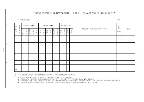
密备注: 进考场时间:出考场时间:甘肃省锅炉压力容器射线检测Ⅱ(复Ⅱ)级人员评片考试底片评片表 底片组编号(袋号):1、评片考试限1小时完成,复试成绩系数为1(满分100分),取证成绩系数为0.6(满分60分)
2、代号:L--裂纹、H--未熔合、T--未焊透、Z--条状夹渣、K--条状气孔、Y--圆形缺陷。
考试日期:考
号
5、“底片编号”栏不填写、但要依次评定:“板厚或规格”栏按底片上所给定数据填写:母材缺陷及表面缺陷在“备注”栏内注明。
主考人: 监考人:4、“缺陷的定性、定量、定位”一栏相当于一张底片,在其上须标出缺陷的性质代号(见备注2)、大致图形及长度(mm)、点数,其位置应与底片中缺陷所在的位置对应。
3、“焊接方法”、“施焊位置”将所选定结果在相应栏内画“○”;“底片质量”栏内不符合标准要求的画“X”、反之画“○”。
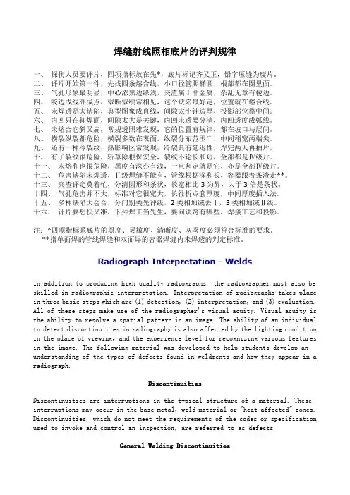
焊缝射线照相底片的评判规律一、探伤人员要评片,四项指标放在先*,底片标记齐又正,铅字压缝为废片。
二、评片开始第一件,先找四条熔合线,小口径管照椭圆,根部都在圈里面。
三、气孔形象最明显,中心浓黑边缘浅,夹渣属于非金属,杂乱无章有棱边。
四、咬边成线亦成点,似断似续常相见,这个缺陷最好定,位置就在熔合线。
五、未焊透是大缺陷,典型图象成直线,间隙太小钝边厚,投影部位靠中间。
六、内凹只在仰焊面,间隙太大是关键,内凹未透要分清,内凹透度成弧线。
七、未熔合它斜又扁,常规透照难发现,它的位置有规律,都在坡口与层间。
八、横裂纵裂都危险,横裂多数在表面,纵裂分布范围广,中间稍宽两端尖。
九、还有一种冷裂纹,热影响区常发现,冷裂具有延迟性,焊完两天再拍片。
十、有了裂纹很危险,斩草除根保安全,裂纹不论长和短,全部都是Ⅳ级片。
十一、未熔和也很危险,黑度有深亦有浅,一旦判定就是它,亦是全部Ⅳ级片。
十二、危害缺陷未焊透,Ⅱ级焊缝不能有,管线根据深和长,容器跟着条渣走**。
十三、夹渣评定莫着忙,分清圆形和条状,长宽相比3为界,大于3倍是条状。
十四、气孔危害并不大,标准对它很宽大,长径折点套厚度,中间厚度插入法。
十五、多种缺陷大会合,分门别类先评级,2类相加减去Ⅰ,3类相加减Ⅱ级。
十六、评片要想快又准,下拜焊工当先生,要问诀窍有哪些,焊接工艺和投影。
注:*四项指标系底片的黑度、灵敏度、清晰度、灰雾度必须符合标准的要求。
**指单面焊的管线焊缝和双面焊的容器焊缝内未焊透的判定标准。
Radiograph Interpretation - WeldsIn addition to producing high quality radiographs, the radiographer must also be skilled in radiographic interpretation. Interpretation of radiographs takes place in three basic steps which are (1) detection, (2) interpretation, and (3) evaluation. All of these steps make use of the radiographer's visual acuity. Visual acuity is the ability to resolve a spatial pattern in an image. The ability of an individual to detect discontinuities in radiography is also affected by the lighting condition in the place of viewing, and the experience level for recognizing various features in the image. The following material was developed to help students develop an understanding of the types of defects found in weldments and how they appear in a radiograph.DiscontinuitiesDiscontinuities are interruptions in the typical structure of a material. These interruptions may occur in the base metal, weld material or "heat affected" zones. Discontinuities, which do not meet the requirements of the codes or specification used to invoke and control an inspection, are referred to as defects.General Welding DiscontinuitiesThe following discontinuities are typical of all types of welding.Cold lap is a condition where the weld filler metal does not properly fuse with the base metal or the previous weld pass material (interpass cold lap). The arc does not melt the base metal sufficiently and causes the slightly molten puddle to flow into base material without bonding.Porosity气孔is the result of gas entrapment in the solidifying metal. Porosity can take many shapes on a radiograph but often appears as dark round or irregular spots or specks appearing singularly, in clusters or rows. Sometimes porosity is elongated and may have the appearance of having a tail This is the result of gas attempting to escape while the metal is still in a liquid state and is called wormhole porosity. All porosity is a void in the material it will have a radiographic density more than the surrounding area..Cluster porosity链状气孔is caused when flux coated electrodes are contaminated with moisture. The moisture turns into gases when heated and becomes trapped in the weld during the welding process. Cluster porosity appear just like regular porosity in the radiograph but the indications will be grouped close together.Slag inclusions夹渣 are nonmetallic solid material entrapped in weld metal or between weld and base metal. In a radiograph, dark, jagged asymmetrical shapes within the weld or along the weld joint areas are indicative of slag inclusions.Incomplete penetration (IP) or lack of penetration (LOP)未焊透occurs when the weld metal fails to penetrate the joint. It is one of the most objectionable weld discontinuities. Lack of penetration allows a natural stress riser from which a crack may propagate. The appearance on a radiograph is a dark area with well-defined, straight edges that follows the land or root face down the center of the weldment.Incomplete fusion未熔合is a condition where the weld filler metal does not properly fuse with the base metal. Appearance on radiograph: usually appears as a dark line or lines oriented in the direction of the weld seam along the weld preparation or joining area.Internal concavity or suck back内凹或吸入is condition where the weld metal has contracted as it cools and has been drawn up into the root of the weld. On a radiograph it looks similar to lack of penetration but the line has irregular edges and it is often quite wide in the center of the weld image.Internal or root undercut内部或根部咬边is an erosion of the base metal next to the root of the weld. In the radiographic image it appears as a dark irregular line offset from the centerline of the weldment. Undercutting is not as straight edged as LOP because it does not follow a ground edge.External or crown undercut外部或顶部咬边is an erosion of the base metal next to the crown of the weld. In the radiograph, it appears as a dark irregular line along the outside edge of the weld area.Offset or mismatch错边are terms associated with a condition where two pieces being welded together are not properly aligned. The radiographic image is a noticeable difference in density between the two pieces. The difference in density is caused by the difference in material thickness. The dark, straight line is caused by failure of the weld metal to fuse with the land area.Inadequate weld reinforcement未填满is an area of a weld where the thickness of weld metal deposited is less than the thickness of the base material. It is very easy to determine by radiograph if the weld has inadequate reinforcement, because the image density in the area of suspected inadequacy will be more (darker) than the image density of the surrounding base material.Excess weld reinforcement增强余高is an area of a weld, which has weld metal added in excess of that specified by engineering drawings and codes. The appearance on a radiograph is a localized, lighter area in the weld. A visual inspection will easily determine if the weld reinforcement is in excess of that specified by the individual code involved in the inspection.Cracking裂纹can be detected in a radiograph only the crack is propagating in a direction that produced a change in thickness that is parallel to the x-ray beam. Cracks will appearas jagged and often very faint irregular lines. Cracks can sometimes appearing as "tails" on inclusions or porosity.Discontinuities in TIG weldsThe following discontinuities are peculiar to the TIG welding process. These discontinuities occur in most metals welded by the process including aluminum and stainless steels. The TIG method of welding produces a clean homogeneous weld which when radiographed is easily interpreted.Tungsten inclusions. 夹钨Tungsten is a brittle and inherently dense material used in the electrode in tungsten inert gas welding. If improper welding procedures are used, tungsten may be entrapped in the weld. Radiographically, tungsten is more dense than aluminum or steel; therefore, it shows as a lighter area with a distinct outline on the radiograph.Oxide inclusions夹氧化物are usually visible on the surface of material being welded (especially aluminum). Oxide inclusions are less dense than the surrounding materials and, therefore, appear as dark irregularly shaped discontinuities in the radiograph.Discontinuities in Gas Metal Arc Welds (GMAW)The following discontinuities are most commonly found in GMAW welds.Whiskers are short lengths of weld electrode wire, visible on the top or bottom surface of the weld or contained within the weld. On a radiograph they appear as light, "wire like" indications.Burn through (icicles) results when too much heat causes excessive weld metal to penetrate the weld zone. Lumps of metal sag through the weld creating a thick globular condition on the back of the weld. On a radiograph, burn through appears as dark spots surrounded by light globular areas.welld-02 (Incomplete Root Fusion、根部未熔合)—welld-03 (Insuffucient Reinforcement、增强高)——welld-04 (Excess Root Penetration、根部焊瘤)——welld-05 (External Undercut、外部咬肉)——welld-06 (Internal Undercut、内部咬肉)——welld-07 (Root Concavity、根部凹陷)——welld-08 (Burn Through、烧穿)——welld-09 (Isolated Slag Inclusion、单个的夹渣)——welld-10 (Wagon Track - Slag Line、线状夹渣)——welld-11 (Interrun Fusion、内部未熔合)——welld-12 (Lack of Sidewall Fusion、内侧未熔合)——welld-13 (Porosity、气孔)——welld-14 (Cluster Porosity、链状气孔)——welld-15 (Hollow Bead、夹珠)——welld-16 (Transverse Crack、横向裂纹)——welld-17 (Centerline Crack、中心线裂纹)——welld-18 (Root Crack、根部裂纹)——welld-19 (Tungsten Inclusion)夹钨—。
焊缝射线探伤底片的评定-tukingcai的日志-网易博客二、底片质量的评定1.测黑度值黑度值(黑化程度,含Ag越多,则黑度较大)可用黑度计(光密度计)直接测量规定部位。
D=lg L0:照射光强;L:透过光强。
底片初始灰雾度D0:指未经曝光的胶片经显影处理后获得的微小黑度。
D0<0.2,影响不大;D0>0.2,则降低对比度和灵敏度。
2.测灵敏度灵敏度是以底片上的象质影像反映的象质指数来表示的。
底片上必须有象质计显示,且位置正确,被检测部位必须达到线型象质计的选用灵敏度要求。
线型象质计的选用定位标记、识别标记与B标记等是否正确、齐全。
4.检验表面质量影像规整齐全,不可缺边或缺角,无伪缺陷。
常见伪缺陷及其原因三、底片上缺陷影像的识别1.焊接缺陷在射线探伤中的显示(见书P/153 表7-1)焊接缺陷显示特点2.焊接缺陷的识别(1)几何形状(2)黑度分布(3)位置四、焊接缺陷的定量测定1.埋藏深度的确定5.在射线方向的尺寸(见书P/155)图7-19五、焊缝质量的评定缺陷:圆形缺陷(长宽比≤3)、条状夹渣(长宽比>3)、未焊透、未熔合、裂纹。
焊缝质量分级表1.圆形缺陷的评定步骤:先确定评定区域、量缺陷的长径、换算成点数、再评级。
①选定评定区域圆形缺陷是长宽比≤3的缺陷,它的评定区域见下表。
缺陷评定区域表单位: mm寸换算成缺陷点数。
当缺陷的尺寸小于不计点数的缺陷尺寸表规定时,分级评定时不计该缺陷的点数。
质量等级为Ⅰ级的对接焊接接头和母材公称厚度小于等于5mm的Ⅱ级对接焊接接头,不计点数的缺陷在圆形缺陷评定区域内不得多于10个,超过时对接焊接接头的质量等级应降低一级。
缺陷点数换算表圆形缺陷的分级表(1)出现缺陷长径大于1/2T的圆形缺陷时,评为Ⅳ级;(2)当缺陷与评定区边界相接时,应把它划为评定区内计算点数;(3)对于Ⅰ级焊缝和母材厚度≤5mm的Ⅱ级焊缝,不计点数的圆形缺陷在评定区内不得多于10个;(4)当评定区附近缺陷较少时,且认为只用该评定区大小划分级别不适当时,可将评定区沿焊缝方向扩大到3倍,求出缺陷点数,用此值的1/3进行评定。