防爆单回路数显表
- 格式:pdf
- 大小:203.15 KB
- 文档页数:19
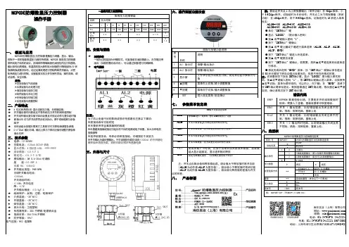
NCPCDE防爆数显压力控制器操作手册一、概述与应用NCPCDE防爆数显压力控制器是集压力测量、显示、输出、控制于一体的智能数显压力测控传感器。
NCPCDE 智能压力控制器采用纯电子结构的设计,前端采用带隔离膜充油压阻式压力传感器,输出信号由高精度,低温漂的放大器作放大处理进行高精度的A/D 转换器转换成数字信号,经过运算处理进行控制两路开关输出,对控制系统压力进行控制。
该智能数字压力开关使用灵活,操作简单,调试容易,安全可靠。
应用:➢空压设备与气动设备➢水泵设备与水处理工程➢液压设备与流体工程➢制药设备与石化工程➢环保设备与环境工程➢实验设备与测量控制二、产品特点★ 4 位红色高亮LED 显示当前压力值,无视值误差。
★开关输出值可任意设定不受传统压力开关机械回差限制★开关动作输出复位值可自由设置且可设定动作与复位延时值★面板LED 灯与开关动作同步发光指示,便于现场观察与设备维护★本体设组合按键无需其它工具即可可方便现场调整各参数★0/4~20mA 输出可调,输出上限与下限对应值可调整方便各种场合应用三、技术参数★电源:12-30VDC★空载电流:≤30mA,DC24V供电★显示范围:4 位红色 LED,-999-9999★综合精度:≤0.5 F.S★稳定性:≤0.3 F.S/年★模拟输出:3W 0/4-20mA 可调精度度:≤0.5F.S负载 RA: ≤500Ω★开关输出类型:PNP/NPN可调开关输出电流:≤500mA开关响应时间:≤10Ms 开关电压降:<1V开关输出精度:≤0.5F.S★线路保护:反相、过载、短路保护★介质温度:-20~85℃★环境温度:-20~60℃★储存温度:-30~60℃★表头外壳:工程塑料★传感器壳体:304 不锈钢/电镀铝合金★接液材质:304/316L不锈钢★防护等级:IP67电气连接:M12 连接器一般常用压力范围等级常用压力范围等级名称压力范围Bar 1510 16 25 60 100 160 250 400 600PSI 15 75 145 230 370 900 1500 2300 3600 6000 9000过载压力X 5 X 3 X 2 X 1.5X1.3破坏压力X 6 X 4 X 3 X 2X1.6四、安装与接线★机械安装一般为过程连接为外螺纹式,可直接装在液压管路上。

防爆型电子称重仪表Ex-XK3118K使用说明书2014年7月版●使用前请仔细阅读本产品说明书●请妥善保管本产品说明书,以备查阅宁波柯力传感科技股份有限公司目录第一章仪表说明 (2)第一节安装连接及特性说明仪表概述 (2)第二节防爆等级介绍 (2)第三节安装连接及特性说明 (2)第四节按键与指示说明 (3)第二章标定调试 (4)第一节标定方法 (4)第二节内码显示 (5)第三节错误信息提示 (5)第三章基本操作和参数设置 (5)第一节基本操作 (5)第二节参数设置 (6)第四章通讯格式说明 (6)第一节连续方式通讯格式 (6)第二节指令通讯格式 (8)第五章信息提示 (9)2防爆型电子称重仪表使用注意事项宁波柯力传感科技股份有限公司生产的Ex-XK3118K 防爆型电子称重仪表经国家级仪器仪表防爆安全监督检验站(NEPSI )检验认可,防爆安全性能符合GB3836.1-2010、GB3836.2-2010、GB3836.4-2010和GB3836.20-2010的有关要求,防爆标志为Exd[ia ⅡCGa]ⅡBT6Gb ,防爆合格证号GYB14.1688X 。
用户在使用安装该产品时,需注意以下事项:1.该产品的使用环境温度范围为:-10℃~+40℃。
2.产品安装、使用和维护严格遵守“严禁带电开盖”的原则。
3.选用的阻燃密封电缆护套外径应与电缆引入装置密封圈内径相适应。
外购的电缆引入装置的使用,维护应遵守其产品使用说明书有关规定。
4.产品设有接地端子,用户在安装使用时应可靠接地。
5.本安输出参数及外部参数如下:最大外部参数最高输出电压Uo(V)最大输出电流Io(mA)最大输出功率Po(W)Co(µF)Lo(mH)6.32400.378150.3应用表格中最大外部参数时,应注意下列要求:-当外部电路仅含分布电容或分布电感时,例如电缆的分布电容和电感,允许的最大外部参数为表格允许值;-对于同时存在电容和电感的外部电路(不包括电缆分布参数),当电容或电感不超过表格中Co ,Lo 的1%时,允许的最大外部参数为表格允许值;-对于同时存在电容和电感的外部电路(不包括电缆分布参数),当电容和电感均大于表格中Co ,Co ,Lo 的1%时,允许的最大外部参数为表格允许值的50%;6.使用现场不存在对铝合金外壳有腐蚀作用的有害气体。
T100XD防爆称重显示器说明书
一、显示器说明
1、样速度:10次/秒。
2、传器灵敏度范围:1.5-3mV/V。
3、分度:1/2/5/10/20/50可选。
4、显示:6位LCD/LED,6个状态指示。
5、大屏幕显示接口(可选)、采用串行输出方式、电流环信号,传输距离≤50米。
6、通讯接口(可选):RS232C。
波特率1200/2400/4800/9600可使用电源:蓄电池DC6V/4AH(当电源电压小于5.4V时,显示Bat_lo 报警)。
7、使用温度、湿度:0-40℃、<85%RH-25-55℃
二.键盘功能
1、功能:在称重状态时,按此键大于5秒,进入用户设置模式。
按此键小于5秒,进入计数状态。
2、在计数状态时,按此键进入取样样本数输入状态。
3、去皮:在称重状态时,按此键去除皮重。
4、置零:在称重状态时,按此键重量显示为零。
5开/关:在关机状态时,按此键开机,在开机状态,按此键关机。
(A12E无此键)。
三.传感器与仪表的连接
1、传器的接采用9芯插头座,图2-3标注了各引脚的意义。
2、使用四芯屏蔽电缆,本仪表无长线补偿。
3、传感器与仪表的联接必须可靠,传感器的屏蔽线必须可靠接地。
联接线不允许在仪表通电的状态下进行插拔,防止静电损坏仪表或传感器。
4、传器和仪表都是静电敏感设备,在使用中必须切实采取防静电措施,严禁在秤台上进行电焊操作或其他强电操作。
在雷雨季节,必须落实可靠的避雷措施,防止因雷击造成传感器和仪表的损坏,确保操作人员的人身安全和称重设备及相关设备的安全运行。
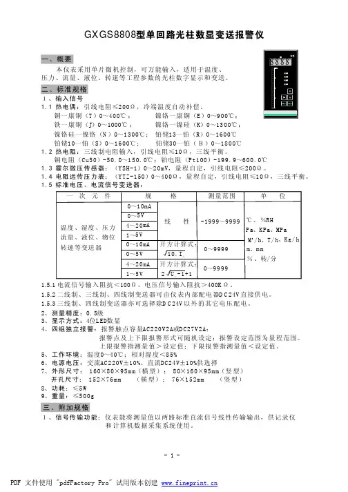
一、产品概述1、SWP-D80系列数显表采用微处理器进行控制运算。
2、SWP-D80系列数显表该仪表集数字仪表与模拟仪表于一体,可对温度、压力、液位、速度等测量信号进行数字量显示控制(高亮度LED数码显示)及相对模拟量显示(光柱显示),使测量值的显示更为清晰直观。
3、SWP-D80系列数显表广泛适用于航空、石油、化工、水泥厂、制药厂、制糖厂、造纸厂、自动化安装工程、染色生产设备等行业中。
二、技术参数规格说明使用环境环境温度 0~50℃相对湿度≤85RH 避免强腐蚀气体供电电压常规型 AC220V+10-15%(50Hz±2Hz)特殊型 AC85~260V——开关电源DC24V ±2V——开关电源功耗•≤6W(AC220V 线性电源供电)•≤6W(AC85~260V 开关电源供电)•≤6W(DC24V 开关电源供电)输入信号模拟量热电偶:标准热电偶——B、S、K、E、J、T、WRe3-25等电阻:标准热电阻——Pt10、Pt100.1、Cu50、Cu100 等远传压力电阻等电流:0~10mA、4~20mA、0~20mA等——输入阻抗≤250Ω电压:0~5V、1~5V、mV等——输入阻抗≥250KΩ开关量脉冲信号:波形——矩形、正弦或三角波辐度——大于4V(或根据用户要求任定)范围——0~10KHz(或根据用户要求任定)接点信号:电接点输入信号输出信号模拟量输出 DC 0~10mA(负载电阻≤750Ω) DC 4~20mA(负载电阻≤500Ω)DC 0~5V(负载电阻≥250KΩ) DC 1~5V(负载电阻≥250KΩ)开关量输出继电器控制输出-继电器ON/OFF带回差。
AC 220V/3A DC 24V/5A(阻性负载)可控硅控制输出-SCR(可控硅过零触发脉冲)输出,0.5A/400V固态继电器输出-SSR(固态继电器控制信号)输出,6~24V/30mA(电压不可调)双向可控硅输出-SOT可控硅输出,5A/400V通讯输出接口方式——标准串行双向通讯接口 RS-485、 RS-232 C、RS-422等波特率——300~9600bps 仪表内部自由设定馈电输出 DC 24V 负载≤30mA测量精度±0.2%FS±1字或±0.5%FS±1字分辨率±1字测量范围 -1999~9999字显示方式 -1999~9999字测量值显示 -1999~9999字设定值显示发光二级管工作状态显示方式控制/报警方式为带回差上限或下限报警(用户可自由设定)控制精度±1字温度补偿 0~50℃数字式温度自动补偿打印控制可选择直接配接各型串打印机(如LQ-300K,TPuP系列微打等),打印接口为RS-232C打印精度同仪表精度参数设定面板轻触式按键设定、参数设定值断电后永久保存、参数设定值密码锁定保护方式输入回路断线报警(热电偶或电阻输入时)、断电器输出状态LED指示、输入超/欠量程报警、电源欠压自动复位、工作异常自动复位(Watch Dog)三、产品型号SWP-D80数字显示控制仪1、SWP-D823/821系列双路数字显示控制仪SWP-D823-022-23/23-HL/HL SWP-D823-011-23/23-HL/HLSWP-D823-822-23/23-HL/HL SWP-D823-811-23/23-HL/HLSWP-D823-222-23/23-HL/HL SWP-D823-211-23/23-HL/HLSWP-D823-020-23/23-HL/HL SWP-D823-010-23/23-HL/HLSWP-D823-021-23/23-HL/HL SWP-D823-012-23/23-HL/HLSWP-D823-022-23/12-HL/HL SWP-D823-011-23/12-HL/HLSWP-D823-822-23/12-HL/HL SWP-D823-811-23/12-HL/HLSWP-D823-222-23/12-HL/HL SWP-D823-211-23/12-HL/HLSWP-D823-020-23/12-HL/HL SWP-D823-010-23/12-HL/HLSWP-D823-021-23/12-HL/HL SWP-D823-012-23/12-HL/HLSWP-D823-022-23/08-HL/HL SWP-D823-011-23/08-HL/HLSWP-D823-822-23/08-HL/HL SWP-D823-811-23/08-HL/HLSWP-D823-222-23/08-HL/HL SWP-D823-211-23/08-HL/HLSWP-D823-020-23/08-HL/HL SWP-D823-010-23/08-HL/HLSWP-D823-021-23/08-HL/HL SWP-D823-012-23/08-HL/HLSWP-D821-022-23/23-N SWP-D821-00-23/23-N SWP-D821-822-23/23-N SWP-D821-80-23/23-N SWP-D821-222-23/23-N SWP-D821-20-23/23-N SWP-D821-020-23/23-N SWP-D821-00-23/23-N SWP-D821-022-23/12-N SWP-D821-00-23/12-N SWP-D821-822-23/12-N SWP-D821-80-23/12-N SWP-D821-222-23/12-N SWP-D821-20-23/12-N SWP-D821-020-23/12-N SWP-D821-00-23/12-N SWP-D821-022-23/08-N SWP-D821-00-23/08-N SWP-D821-822-23/08-N SWP-D821-80-23/08-N SWP-D821-222-23/08-N SWP-D821-20-23/08-N SWP-D821-020-23/08-N SWP-D821-00-23/08-N2、SWP-D805系列PID自整定控制仪SWP-D805-020-23-HL SWP-D805-010-23-HL SWP-D805-020-22-HL SWP-D805-010-22-HL SWP-D805-020-21-HL SWP-D805-010-21-HLSWP-D805-020-20-HL SWP-D805-010-20-HL SWP-D805-020-19-HL SWP-D805-010-19-HL SWP-D805-020-18-HL SWP-D805-010-18-HLSWP-D805-020-17-HL SWP-D805-010-17-HL SWP-D805-020-16-HL SWP-D805-010-16-HL SWP-D805-020-15-HL SWP-D805-010-15-HLSWP-D805-020-14-HL SWP-D805-010-14-HL SWP-D805-020-13-HL SWP-D805-010-13-HL SWP-D805-020-12-HL SWP-D805-010-12-HLSWP-D805-020-11-HL SWP-D805-010-11-HL SWP-D805-020-10-HL SWP-D805-010-10-HL SWP-D805-020-09-HL SWP-D805-010-09-HLSWP-D805-020-08-HL SWP-D805-010-08-HL SWP-D805-020-07-HL SWP-D805-010-07-HL SWP-D805-020-06-HL SWP-D805-010-06-HLSWP-D805-020-05-HL SWP-D805-010-05-HL SWP-D805-020-04-HL SWP-D805-010-04-HL SWP-D805-020-03-HL SWP-D805-010-03-HLSWP-D805-020-02-HL SWP-D805-010-02-HLSWP-D805-020-01-HL SWP-D805-010-01-HL3、SWP-D815系列PID外给定控制仪SWP-D815-020-23/12-HL SWP-D815-010-23/12-HL SWP-D815-020-23/08-HLSWP-D815-010-23/08-HL SWP-D815-020-12/12-HL SWP-D815-010-12/12-HLSWP-D815-020-23/22-HL SWP-D815-010-23/22-HL SWP-D815-020-23/21-HLSWP-D815-010-23/21-HL SWP-D815-020-12/20-HL SWP-D815-010-12/20-HLSWP-D815-020-23/19-HL SWP-D815-010-23/19-HL SWP-D815-020-23/18-HLSWP-D815-010-23/18-HL SWP-D815-020-12/17-HL SWP-D815-010-12/17-HLSWP-D815-020-23/16-HL SWP-D815-010-23/16-HL SWP-D815-020-23/15-HLSWP-D815-010-23/15-HL SWP-D815-020-12/14-HL SWP-D815-010-12/14-HL SWP-D815-020-23/13-HL SWP-D815-010-23/13-HL SWP-D815-020-23/11-HL SWP-D815-010-23/11-HL SWP-D815-020-12/10-HL SWP-D815-010-12/10-HL SWP-D815-020-23/09-HL SWP-D815-010-23/09-HL SWP-D815-020-23/07-HL SWP-D815-010-23/07-HL SWP-D815-020-12/06-HL SWP-D815-010-12/06-HL SWP-D815-020-23/05-HL SWP-D815-010-23/05-HL SWP-D815-020-23/04-HL SWP-D815-010-23/04-HL SWP-D815-020-12/03-HL SWP-D815-010-12/03-HL SWP-D815-020-23/02-HL SWP-D815-010-23/02-HLSWP-D815-020-23/01-HL SWP-D815-010-23/01-HL4、SWP-D825系列PID阀位控制仪SWP-D825-020-23/12-HL SWP-D825-010-23/12-HL SWP-D825-020-23/08-HL SWP-D825-010-23/08-HL SWP-D825-020-12/12-HL SWP-D825-010-12/12-HL SWP-D825-020-23/22-HL SWP-D825-010-23/22-HL SWP-D825-020-23/21-HL SWP-D825-010-23/21-HL SWP-D825-020-12/20-HL SWP-D825-010-12/20-HL SWP-D825-020-23/19-HL SWP-D825-010-23/19-HL SWP-D825-020-23/18-HL SWP-D825-010-23/18-HL SWP-D825-020-12/17-HL SWP-D825-010-12/17-HL SWP-D825-020-23/16-HL SWP-D825-010-23/16-HL SWP-D825-020-23/15-HL SWP-D825-010-23/15-HL SWP-D825-020-12/14-HL SWP-D825-010-12/14-HL SWP-D825-020-23/13-HL SWP-D825-010-23/13-HL SWP-D825-020-23/11-HL SWP-D825-010-23/11-HL SWP-D825-020-12/10-HL SWP-D825-010-12/10-HL SWP-D825-020-23/09-HL SWP-D825-010-23/09-HL SWP-D825-020-23/07-HL SWP-D825-010-23/07-HL SWP-D825-020-12/06-HL SWP-D825-010-12/06-HL SWP-D825-020-23/05-HL SWP-D825-010-23/05-HL SWP-D825-020-23/04-HL SWP-D825-010-23/04-HL SWP-D825-020-12/03-HL SWP-D825-010-12/03-HL SWP-D825-020-23/02-HL SWP-D825-010-23/02-HLSWP-D825-020-23/01-HL SWP-D825-010-23/01-HL5、SWP-D835系列手动操作器SWP-D835-020-23/12-HL SWP-D835-010-23/12-HL SWP-D835-020-23/08-HL SWP-D835-010-23/08-HL SWP-D835-020-12/12-HL SWP-D835-010-12/12-HL SWP-D835-020-23/22-HL SWP-D835-010-23/22-HL SWP-D835-020-23/21-HL SWP-D835-010-23/21-HL SWP-D835-020-12/20-HL SWP-D835-010-12/20-HL SWP-D835-020-23/19-HL SWP-D835-010-23/19-HL SWP-D835-020-23/18-HL SWP-D835-010-23/18-HL SWP-D835-020-12/17-HL SWP-D835-010-12/17-HL SWP-D835-020-23/16-HL SWP-D835-010-23/16-HL SWP-D835-020-23/15-HL SWP-D835-010-23/15-HL SWP-D835-020-12/14-HL SWP-D835-010-12/14-HL SWP-D835-020-23/13-HL SWP-D835-010-23/13-HL SWP-D835-020-23/11-HL SWP-D835-010-23/11-HL SWP-D835-020-12/10-HL SWP-D835-010-12/10-HL SWP-D835-020-23/09-HL SWP-D835-010-23/09-HL SWP-D835-020-23/07-HL SWP-D835-010-23/07-HL SWP-D835-020-12/06-HL SWP-D835-010-12/06-HL SWP-D835-020-23/05-HL SWP-D835-010-23/05-HL SWP-D835-020-23/04-HL SWP-D835-010-23/04-HL SWP-D835-020-12/03-HL SWP-D835-010-12/03-HL SWP-D835-020-23/02-HL SWP-D835-010-23/02-HLSWP-D835-020-23/01-HL SWP-D835-010-23/01-HL。

兖州鑫泉工业自动化有限公司,公司自主研制开发FB系列智能防爆数显控制仪表,采用最新微处理器技术,充分结合国内工业生产环境的具体要求,引进国
际先进的电子技术及设备,严格按照ISO9001标准组织生产。
所有产品都经过
严格的质量检验,品质可靠,性能优异。
用户遍布全国二十多个省市的石油、
化工、制药行业。
1、性能概述
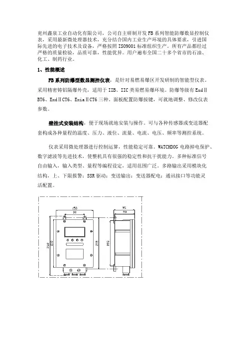
FB系列防爆型数显测控仪表,是针对易燃易爆区开发研制的智能型仪表。
采用精密铸铝隔爆外壳,适用于IIB、IIC类易燃易爆环境。
防爆等级有ExdⅡBT6、ExdⅡCT6、ExiaⅡCT6三种。
面板配置防爆按键,可就地调整、修改仪表
参数。
壁挂式安装结构,便于现场就地安装与操作。
可与各种传感器或变送器配
套构成各种量程的温度、压力、液位、流量、电流、电压、频率等测控系统。
仪表采用微处理器进行控制运算,性能稳定可靠。
WATCHDOG电路掉电保护、数字滤波等先进技术,使整机具有很强的稳定性和抗干扰能力。
多种标准信号
自由输入,输入类型、量程等编程设定,适用范围广泛。
多路输出采用模块化
结构,上、下限报警;SSR驱动;变送输出;变送器配电;通讯接口等功能灵
活配置。
浙制00000690号XK3150-Exd防爆型称重仪表使用说明书宁波朗科精工技术有限公司注意事项由宁波朗科精工技术有限公司生产的XK3150-Exd型防爆型称重仪表国家级仪器仪表防爆安全监督检验站(NEPSI)检验,符合GB3836.1-2010、GB3836.2-2010、GB3836.4-2010和GB3836.20-2010标准的有关要求,其防爆标志为Ex d [ia Ga]ⅡB T6 Gb,防爆合格证号为GYB12.1139X。
本次认可的产品使用应遵循下列事项如下:1、产品防爆合格证号后缀“X”代表产品使用有特殊要求:涉及隔爆接合面的维修须联系产品制造商。
2、产品安全栅本安端参数:YB958H安全栅:U0=7.5V; I0=560mA ; P0=1.1W; C0=11μF; L0=70μH。
YB964H安全栅:U0=12V; I0=12mA ; P0=38mW; C0=1.0μF; L0=160mH。
3、产品使用环境温度:-10℃~+40℃。
4、产品隔爆部件现场使用应遵守“严禁带电开盖”的原则。
5、电缆引入口必须配用经防爆检验认可、具有防爆等级为Ex dⅡB、螺纹规格为G1/2的电缆引入装置, 与壳体构成的隔爆螺纹接合面啮合扣数应不小于5扣。
同时,电缆引入装置的使用必须符合其使用说明书的要求。
6、产品外壳设有接地端子,用户在安装使用时应可靠接地。
7、用户不得自行更换该产品的零部件,应会同产品制造商共同解决运行中出现的故障,以杜绝损坏现象的发生。
8、用户在安装、使用和维护本产品时须同时遵守产品使用说明书、GB3836.13-1997“爆炸性气体环境用电气设备第13部分:爆炸性气体环境用电气设备的检修”、GB3836.15-2000“爆炸性气体环境用电气设备第15部分:危险场所电气安装(煤矿除外)”、GB3836.16-2006“爆炸性气体环境用电气设备第16部分:电气装置的检查和维护(煤矿除外)”和GB50257-1996“电气装置安装工程爆炸和火灾危险环境电力装置施工及验收规范”和的有关规定。
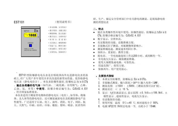
·本安防爆,安全性好!·数字保持,读数方便!·数字显示,分辨率高!·测量准确,显示迅速!·体积小,重量轻!·欠压指示,确保准确!·用途广泛,携带方便!·耗电极小,使用方便!·可靠性高,保修两年!EST101型防爆静电电压表(使用说明书)北京市劳动保护科学研究所一. 概述EST101型防爆静电电压表是在吸收国内外先进静电仪表的基础上,经广大用户多年使用并多次改进的新型高性能、低价格静电电压表(静电电位计)。
本仪表防爆性能好,防爆标志为iaⅡCT6。
能在各类爆炸性气体(如汽油、二硫化碳、市用煤气、乙烯、乙炔、氢、苯等)中使用。
防爆合格证编号为:CJEx02.4.031。
符合国家标准要求。
本仪表适用于测量带电物体的静电电压(电位),如导体、绝缘体、及人体等的静电电位。
还可测量液面电位及检测防静电产品性能等。
广泛适用于石油、化工、油库、消防、电子、国防、航天、天然气、印刷、纺织、印染、橡胶、塑料、喷涂、医药等科研、生产、储运安全管理部门中有关静电的测量。
是现场静电检测的理想仪表二、特点●能在各类爆炸性环境中使用,防爆性能好,防爆标志为ExiaⅡCT6.防爆合格证编号为:CJEx02.4.031●数字显示,分辨率高。
●有读数保持功能。
读数准确方便。
●非接触式旧子测量,对被测物体影响小。
●测量准确迅速。
测量速率约3次/秒。
●体积小,重量轻,携带方便。
●耗电省,一节电池能连续工作达200小时,或间断约一年。
•有电池欠压显示,确保测量准确。
•使用大规模集成电路,可靠性高。
•用途范围广。
使用方便。
•保修两年,用户使用放心。
三。
主要技术指标1. 本质安全防爆型, 防爆标志:ExiaⅡCT6。
2.非接触式测量。
输入阻抗>1016Ω.输入电容<1PF。
3. 测量范围: ±100V - ±50KV。
(测量范围可以扩展)。
NHR-1100系列简易型单回路数字显示控制仪概述NHR1100系列简易测量显示控制仪采用模块化结构方案,结构简单、操作方便、性价比高,适用于塑料、食品、包装机械等行业。
单路输入,双屏LED数码显示。
具备33种信号输入功能,可任意选择输入信号类型,测量精度为0.3%。
热电阻\热电偶信号分辨率可切换:1℃或0.1℃。
具备上下限报警功能,带LED报警灯指示。
具有电压、电流变送输出信号可选。
支持RS485串行接口,采用标准MODBUS RTU通讯协议。
带DC24V馈电输出,为现场变送器配电。
输入、输出、电源、通讯相互之间采用光电隔离技术。
具备多种外形尺寸及样式供用户选择。
参数设定密码锁定,参数设置断电永久保存。
仪表面板160*80mm(A型)80*160mm(B型)96*96mm(C型)96*48mm(D型)48*96mm(E型)72*72mm(F型)48*48mm(H型)参数功能注:以上参数为仪表全部参数,如果不是全功能仪表,则未选功能所对应的参数将不予显示。
仪表接线图规格尺寸为A、B、C、D、E型接线图注:横竖式仪表后盖接线端子方向不一样,见示意图1。
图一★注:上述接线图中在同一组端子标有不同功能的,只能选择其中一种功能。
如RS485通讯功能和变送输出功能在同一组OUT接线端子上,只能选择一种。
仪表选型NHR-1100□-□-□/□/□( )-□-( )①②③④⑤⑥⑦备注:1、选型时请根据接线图来选择功能,由于尺寸小的仪表接线端子少带不了全功能,有的功能在同组端子上只能选择其中一种功能。
2、在写型号时必须完整,没有选到的功能项不能省略,必须用“X”补上。
例1:NHR-1100A-55-0/2/P(24)-A例2:NHR-1100C-27-0/X/X-D返回上一页 >>。
两款仪表性能参数对比说明:一、33H1‐00000‐A00‐J00‐XX关键参数1) 防尘式 220VAC供电 4-20mA输出2) 防爆等级:Ex nAnL[nL]IICT5/DIP A22 TA100℃,适用于气体2区和粉尘22区危险环境,3)无法配梅特勒专用隔爆箱外观及选型指南如下:二、EXd331‐00000‐A00‐000关键参数a) 220VAC供电 4-20mA输出b) 防爆等级: Ex d[ia] iaⅡC T6 DIPA21 TA T6 满足防爆标准最严要求。
c) 自带一体式隔爆箱外观及选型指南如下EXD331性能特点三、传感器说明3.1 仪表型号 MM CS S2 1100关键参数1) 容量:1100Kg2) 防爆等级:无3) 模块顶板、底板为碳钢,表面镀锌。
3.2 仪表型号 MM CS S2 1100XX关键参数a) 容量:1100Kgb) 防爆等级:ExiaⅡCT4‐T6c) 模块顶板、底板为碳钢,表面镀锌。
性能及特征如下◇ 数量:2套,每套3支◇ 额定输出 (0.85~1.15) mV/V◇ 非线性 0.02 %F.S◇ 滞后 0.02 %F.S◇ 重复性 0.02 %F.S◇ 输出温度影响Temperature Effect On Output 0.002 %R.O./℃ ◇ 零点温度影响Temperature Effect On Zero 0.003 %R.O./℃ ◇ 输入阻抗Input Impedance 410±15 Ω;390±15 Ω◇ 材质:模块顶板、底板为碳钢,表面镀锌。
◇ 防爆等级:ExiaⅡCT4-T6◇ 容量:1100Kg,5米线缆四、关于梅特勒‐托利多防爆仪表箱的选型指南隔爆箱规格及配置:注1: 上述型号隔爆IND331,已包括相应型号的隔爆箱,仪表,其作为一个整体使用。
注2: 除上述标准配置外,如有其他配置应用,请致电梅特勒托利多,共同探讨非标应用,谢谢!。
从外壳中取出表芯的方法仪表的表芯可以从表壳中拔出,其方法是将仪表前面板两侧的锁扣向外侧拨开 , 然后抓住仪表的前面板向外拔 , 即可使表芯与表壳分离。
在回装时 , 将表芯插入表壳后一定要推紧 , 并将锁扣锁紧 , 以保证防护标准。
产品介绍1 显示面板外观结构图2 选型表NHR-1100系列单回路数字显示控制仪 (简易型(1 PV显示窗 (测量值 (2 SV显示窗测量状态下显示输入类型等参数参数设定状态下显示设定值 (3 第一报警 (AL1和第二报警 (AL2指 (4 确认键 (5 移位键(6 减少键 (7 增加键面板使用说明书- 1 -版本号:1100-091217系列备注 :1路继电器 (带有常开常闭触点触点容量:AC220V/3A、 DC30V/5A (阻性负载2路继电器 (仅一组常开触点触点容量:AC220V/3A、 DC30V/5A (阻性负载示灯、运行灯 (RUN和输出灯 (OUTNHR-1100系列单回路数字显示控制仪(简易型 ,傻瓜式操作 ,0.3级测量精度 ,7款外型尺寸 , 双四位 LED 显示,可支持热电偶、热电阻、电压 (可开方运算、电流 (可开方运算及变送器输入 , 适用温度、压力、流量、液位、湿度等工业过程量的监测。
支持 2路报警功能,支持 1路变送输出或支持采用标准 MODBUS 协议的 RS485通讯接口, 1路 DC24V 馈电输出,输入端、输出端、电源端光电隔离, 100-240V AC/DC或 20-29V DC开关电源供电,标准卡入式安装,工作环境温度在 0-50℃,且相对湿度 5-85%RH无凝结。
规格尺寸为 H 的仪表,继电器触点容量:AC220V/0.6A、 DC30V/0.6A(阻性负载- 2 -注 :上述接线图中在同一组端子标有不同功能的 , 只能选择其中一种功能。
如RS485通讯功能和变送输出功能在同一组 OUT 接线端子上, 只能选择一种。
3 接线- 3 -4.1 一级参数设置在工作状态下 ,PV 显示 LOC,SV 显示参数字符:按增加、减少键来进行设置。
一、产品分类防爆仪器仪表类产品2314主要包括以下几类产品:1. 防爆仪表:用于在易燃易爆的环境中进行测量和监控,确保安全生产。
2. 防爆仪器:用于检测和分析用于易燃易爆的环境中的物质的仪器设备。
3. 防爆工具:适用于易燃易爆环境的维修、安装和调试工作所需的工具。
二、产品特点1. 高安全性:防爆仪器仪表类产品2314经过严格的防爆设计和测试,具有良好的防爆性能,确保在危险环境中使用时安全可靠。
2. 精准测量:产品具有高精度的测量功能,能够满足对于在易燃易爆环境中的精准监测和测量需求。
3. 耐用可靠:产品采用优质材料和先进工艺制造,具有耐高温、耐腐蚀、抗震抗压等性能,能够在恶劣环境下长期稳定运行。
4. 易操作维护:产品设计合理,操作简便,维护方便,用户可根据需要快速进行操作和维护。
三、应用领域防爆仪器仪表类产品2314广泛应用于石油、石化、化工、冶金、航天、船舶等行业,具体包括以下几个方面:1. 石油化工:在炼油、化工生产过程中用于监测和控制各种易燃易爆化学品的浓度、压力、温度等参数。
2. 煤矿瓦斯:用于监测煤矿瓦斯浓度,预警和防范瓦斯爆炸事故。
3. 船舶船舵:在船舶船舵系统中用于测量舵机压力、液位和温度等参数,确保舵机系统安全运行。
4. 火箭发射场:在火箭发射场用于监测各种燃料和氧化剂的浓度和压力,确保火箭发射过程中的安全。
5. 石油钻采:在石油钻采过程中用于监测井下气体、油压等参数,确保井下作业安全进行。
四、技术发展趋势随着我国石油、化工、矿山等行业的不断发展,防爆仪器仪表类产品2314的市场需求将会不断增加。
为了满足市场的需求,产品技术发展趋势主要包括以下几个方面:1. 高精度、高可靠性:产品将会朝着精度更高、可靠性更强的方向发展,以满足用户对于精准监测和安全可靠性的需求。
2. 智能化:产品将会加大在智能化方面的研发力度,采用先进的传感器技术、数据处理技术,实现远程监测、自动控制等功能。
3. 多功能化:产品将会朝着一机多能的方向发展,满足用户在不同场景下的多种监测需求。
Quick Start Guide00825-0100-3581, Rev ABApril 2020 Rosemount™ 5081Explosion-Proof, Single-Input Intelligent TransmitterQuick Start Guide April 2020Essential instructionsRead this page before proceeding!Emerson designs, manufactures, and tests its products to meet many national and internationalstandards. Because these instruments are sophisticated technical products, you must properly install, use, and maintain them to ensure they continue to operate within their normal specifications. Youmust adhere to the following instructions and integrate them into your safety program wheninstalling, using, and maintaining Emerson's Rosemount products. Failure to follow the properinstructions may cause any one of the following situations to occur: loss of life, personal injury,property damage, damage to this instrument, and warranty invalidation.•Read all instructions prior to installing, operating, and servicing the product.•If this Quick Start Guide is not the correct one, call 1-800-854-8257 or 949-757-8500 to request the correct Quick Start Guide. Save this Quick Start Guide for future reference.•If you do not understand any of the instructions, contact your Emerson representative for clarification.•Follow all warnings, cautions, and instructions marked on and supplied with the product.•Inform and educate your personnel in the proper installation, operation, and maintenance of the product.•Install equipment as specified in the installation instructions of the appropriate Reference Manual and per applicable local and national codes. Connect all products to the proper electrical andpressure sources.•To ensure proper performance, use qualified personnel to install, operate, update, program, and maintain the product.•When replacement parts are required, ensure that qualified people use replacement parts specified by Emerson. Unauthorized parts and procedures can affect the product's performance,place the safe operation of your process at risk, and VOID YOUR WARRANTY. Look-alikesubstitutions may result in fire, electrical hazards, or improper operation.•Ensure that all equipment doors are closed and protective covers are in place, except when maintenance is being performed by qualified people, to prevent electrical shock and personalinjury.WARNINGPhysical accessUnauthorized personnel may potentially cause significant damage to and/or misconfiguration of end users’ equipment. This could be intentional or unintentional and needs to be protected against.Physical security is an important part of any security program and fundamental to protecting yoursystem. Restrict physical access by unauthorized personnel to protect end users’ assets. This is true for all systems used within the facility.NoticeEMERSON (“SELLER”) SHALL NOT BE LIABLE FOR TECHNICAL OR EDITORIAL ERRORS IN THIS MANUAL OR OMISSIONS FROM THIS MANUAL. SELLER MAKES NO WARRANTIES, EXPRESSED OR IMPLIED,INCLUDING THE IMPLIED WARRANTIES OF MERCHANTABILITY AND FITNESS FOR A PARTICULARPURPOSE, WITH RESPECT TO THIS MANUAL AND, IN NO EVENT, SHALL SELLER BE LIABLE FOR ANYSPECIAL OR CONSEQUENTIAL DAMAGES INCLUDING, BUT NOT LIMITED TO, LOSS OF PRODUCTION,LOSS OF PROFITS, ETC.PRODUCT NAMES USED HEREIN ARE FOR MANUFACTURER OR SUPPLIER IDENTIFICATION ONLY AND MAY BE TRADEMARKS/REGISTERED TRADEMARKS OF THESE COMPANIES./RosemountApril 2020Quick Start Guide THE CONTENTS OF THIS PUBLICATION ARE PRESENTED FOR INFORMATIONAL PURPOSES ONLY, AND WHILE EVERY EFFORT HAS BEEN MADE TO ENSURE THEIR ACCURACY, THEY ARE NOT TO BECONSTRUED AS WARRANTIES OR GUARANTEES, EXPRESSED OR IMPLIED, REGARDING THE PRODUCTS OR SERVICES DESCRIBED HEREIN OR THEIR USE OR APPLICABILITY. WE RESERVE THE RIGHT TOMODIFY OR IMPROVE THE DESIGNS OR SPECIFICATIONS OF SUCH PRODUCTS AT ANY TIME.SELLER DOES NOT ASSUME RESPONSIBILITY FOR THE SELECTION, USE, OR MAINTENANCE OF ANYPRODUCT. RESPONSIBILITY FOR PROPER SELECTION, USE, AND MAINTENANCE OF ANY SELLERPRODUCT REMAINS SOLELY WITH THE PURCHASER AND END-USER.Warranty1.LIMITED WARRANTY: Subject to the limitations contained in Section 2 herein and except asotherwise expressly provided herein, Emerson (“Seller”) warrants that the firmware willexecute the programming instructions provided by Seller and that the Goods manufacturedor Services provided by Seller will be free from defects in materials or workmanship undernormal use and care until the expiration of the applicable warranty period. Goods arewarranted for twelve (12) months from the date of initial installation or eighteen (18) monthsfrom the date of shipment by Seller, whichever period expires first. Consumables andServices are warranted for a period of 90 days from the date of shipment or completion of theServices. Products purchased by Seller from a third party for resale to Buyer (“ResaleProducts”) shall carry only the warranty extended by the original manufacturer. Buyer agreesthat Seller has no liability for Resale Products beyond making a reasonable commercial effortto arrange for procurement and shipping of the Resale Products. If Buyer discovers anywarranty defects and notifies Seller thereof in writing during the applicable warranty period,Seller shall, at its option, promptly correct any errors that are found by Seller in the firmwareor Services, or repair or replace F.O.B. point of manufacture that portion of the Goods orfirmware found by Seller to be defective, or refund the purchase price of the defectiveportion of the Goods/Services. All replacements or repairs necessitated by inadequatemaintenance, normal wear and usage, unsuitable power sources, unsuitable environmentalconditions, accident, misuse, improper installation, modification, repair, storage or handling,or any other cause not the fault of Seller are not covered by this limited warranty, and shall beat Buyer's expense. Seller shall not be obligated to pay any costs or charges incurred by Buyeror any other party except as may be agreed upon in writing in advance by an authorized Sellerrepresentative. All costs of dismantling, reinstallation and freight, and the time and expensesof Seller's personnel for site travel and diagnosis under this warranty clause shall be borne byBuyer unless accepted in writing by Seller. Goods repaired and parts replaced during thewarranty period shall be in warranty for the remainder of the original warranty period orninety (90) days, whichever is longer. This limited warranty is the only warranty made bySeller and can be amended only in a writing signed by an authorized representative of Seller.Except as otherwise expressly provided in the Agreement, THERE ARE NO REPRESENTATIONSOR WARRANTIES OF ANY KIND, EXPRESSED OR IMPLIED, AS TO MERCHANTABILITY, FITNESSFOR PARTICULAR PURPOSE, OR ANY OTHER MATTER WITH RESPECT TO ANY OF THE GOODSOR SERVICES. It is understood that corrosion or erosion of materials is not covered by ourguarantee.2.LIMITATION OF REMEDY AND LIABILITY: SELLER SHALL NOT BE LIABLE FOR DAMAGES CAUSEDBY DELAY IN PERFORMANCE. THE SOLE AND EXCLUSIVE REMEDY FOR BREACH OFWARRANTY HEREUNDER SHALL BE LIMITED TO REPAIR, CORRECTION, REPLACEMENT, ORREFUND OF PURCHASE PRICE UNDER THE LIMITED WARRANTY CLAUSE IN SECTION 1HEREIN. IN NO EVENT, REGARDLESS OF THE FORM OF THE CLAIM OR CAUSE OF ACTION(WHETHER BASED IN CONTRACT, INFRINGEMENT, NEGLIGENCE, STRICT LIABILITY, OTHERTORT, OR OTHERWISE), SHALL SELLER'S LIABILITY TO BUYER AND/OR ITS CUSTOMERSEXCEED THE PRICE TO BUYER OF THE SPECIFIC GOODS MANUFACTURED OR SERVICESPROVIDED BY SELLER GIVING RISE TO THE CLAIM OR CAUSE OF ACTION. BUYER AGREESTHAT IN NO EVENT SHALL SELLER'S LIABILITY TO BUYER AND/OR ITS CUSTOMERS EXTEND TOINCLUDE INCIDENTAL, CONSEQUENTIAL, OR PUNITIVE DAMAGES. THE TERM“CONSEQUENTIAL DAMAGES” SHALL INCLUDE, BUT NOT BE LIMITED TO, LOSS OFANTICIPATED PROFITS, LOSS OF USE, LOSS OF REVENUE, AND COST OF CAPITAL.Quick Start Guide3Quick Start Guide April 2020 ContentsFirst steps (5)Wire (7)Display and operate (11)Start-up (14)Rosemount 5081 - (A/P/C/T) product certifications (15)EU Declarations of Conformity (19)China RoHS Table (25)/RosemountApril 2020Quick Start Guide 1First steps1.1Unpack and inspectTo unpack the instrument:Procedure1.Inspect the shipping container(s). If there is damage, contact theshipper immediately for instructions.2.If there is no apparent damage, unpack the container(s).3.Ensure that all items shown on the packing list are present.If items are missing, contact your local Customer Care representative4.Save the shipping container and packaging.They can be used to return the instrument to the factory in case ofdamage.1.2Installation1.2.1Installation guidelines1.The transmitter tolerates harsh environments. For best results, installthe transmitter in an area where temperature extremes, vibrations,and electromagnetic and radio frequency interference are minimizedor absent.2.To prevent unintentional exposure of the transmitter circuitry to theplant environment, keep the security lock in place over the circuitend cap. To remove the circuit end cap, loosen the lock nut until thetab disengages from the cap end and then unscrew the cover.3.The transmitter has two ¾-in. (19.1 mm) conduit openings, one oneach side of the housing. Run sensor cable through the left sideopening (as viewed from the wiring terminal end of the transmitter)and run power wiring through the right side opening.e water tight cable glands to keep moisture out of the transmitter.5.If using conduit, plug and seal the connections at the transmitterhousing to prevent moisture from getting inside the transmitter.CAUTIONEquipment damageMoisture accumulating in the transmitter housing can affect theperformance of the transmitter and may void the warranty.Quick Start Guide5Quick Start Guide April 20206.If the transmitter is installed some distance from the sensor, aremote junction box with preamplifier in the junction box or in thesensor may be necessary. Consult the sensor Quick Start Guide formaximum cable lengths.1.2.2Orient the display boardThe display board can be rotated 90 degrees, clockwise or counterclockwise,from the original position. To reposition the display:Procedure1.Loosen the cover lock nut until the tab disengages from the circuitend cap. Unscrew the cap.2.Remove the three bolts holding the circuit board stack.3.Lift and rotate the display board 90 degrees, clockwise orcounterclockwise, into the desired position.4.Position the display board on the stand offs. Replace and tighten thebolts.5.Replace the circuit end cap./RosemountApril 2020Quick Start Guide 2Wire2.1Wiring overviewTo find wiring diagrams for specific sensors, check the wiring sections of thereference manuals for those particular sensors.2.2Power supply/current loop2.2.1Power supply overviewThe tables below display the minimum and maximum voltages needed tooperate the transmitter.Quick Start Guide7Figure 2-1: Power Supply Voltage for HART ® or without HARTCommunication ConfigurationsA.With HART communicationB.Without HART communicationTable 2-1: Values from GraphQuick Start Guide April 2020/RosemountApril 2020Quick Start Guide2.2.2Wire the transmitter with HART® or F OUNDATION™ FieldbusProcedure1.Run the power/signal wiring through the opening nearest terminals15 and 16.e shielded cable and ground the shield to the power supply.3.To ground the transmitter, attach the shield to the grounding screwon the inside of the transmitter case.You can also use a third wire to connect the transmitter to earthground.NoteFor optimum electromagnetic interference/radio frequencyinterference (EMI/RFI) immunity, shield the power supply/outputcable and enclose it in an earth grounded metal conduit. Do not runpower supply/signal wiring in the same conduit or cable tray with ACpower lines or with relay actuated signal cables. Keep power supply/signal wiring at least 6 ft. (2 m) away from heavy electricalequipment. An additional 0-1 mA current loop is available betweenTB-14 and TB-15. A 1 mA current in this loop signifies a sensor fault.See Figure 2-2 for wiring instructions.Quick Start Guide9Figure 2-2: General wiring architectureA.Filter B.Terminator C.Trunk D.SpurQuick Start Guide April 2020/Rosemount3Display and operate3.1User interface and main displayThe following are examples of the main (process) display screen (Figure 3-1)and the program display screen (Figure 3-2).Figure 3-1: Main Display ScreenA.Conductivity valueB.Temperature in °C or °FFigure 3-2: Program Display ScreenA.Indicates HART® or F OUNDATION™ Fieldbus digital communiciationsB.Conductivity valueC.Units of displayD.Active menu: CALIBRATE, PROGRAM, or DIAGNOSEE.Sub-menus, prompts, and diagnostic messages appear here.F.Available commands for sub-menus, prompts, or diagnostic messagesG.Appears when transmitter is in holdH.Appears when a disabling condition has occurred3.2Infrared remote control (IRC)Use the IRC to read diagnostics messages, calibrate connected sensors, andprogram the transmitter. Hold the IRC within 6 ft. (1.8 m) of the transmitterand less than 15 degrees from the horizontal of the display window.Figure 3-3: Infrared Remote Control (IRC) Functionstransmitter to factory 6. •7. •••8. •9. •••Guidelines for using IRC•Do not use harsh chemicals or abrasive brushes when cleaning the remote control.•If the green LED does not light when you press a key, the issue isprobably a weak battery. To restore operation, remove four screws toaccess and replace the two batteries. Observe the two warning messagesposted at the rear of the remote control.•Requires two 1.5 V AAA batteries. If used in hazardous areas,replacement batteries must be Energizer E92/EN92 or Duracell MN2400/PC2400.•All functions for remote control PN 24479-00 are the same as those for the previous remote control, PN 23572-00.3.3Menu systemThere are three main menus: Calibrate, Program, and Diagnose. Calibrate andProgram menus have additional sub-menus as shown in the figures below.Table 3-1: Program Menu4Start-upProcedureing the infrared remote control (IRC), press PROG, NEXT, NEXT,and ENTER in this order.2.Select the measurement type and unit of measurement.e the arrow keys to toggle between Celsius and Fahrenheit.4.Press ENTER and then RESET.5.Press PROG, NEXT, and ENTER in this order.e the arrow keys to toggle T AUTO between ON or OFF.This determines whether the transmitter uses the processtemperature (ON) or a manual temperature (OFF).7.Press ENTER.8.If you select OFF, enter the manual temperature desired using thearrow keys.9.Press ENTER.5Rosemount 5081 - (A/P/C/T) productcertificationsRev 1.15.1European Directive informationA copy of the EU Declaration of Conformity can be found at the end of theQuick Start Guide. The most recent revision of the EU Declaration ofConformity can be found at /Rosemount.5.2Ordinary location certificationAs standard, the transmitter has been examined and tested to determinethat the design meets the basic electrical, mechanical, and fire protectionrequirements by a nationally recognized test laboratory (NRTL) as accreditedby the Federal Occupational Safety and Health Administration (OSHA). 5.3Installing equipment in North AmericaThe US National Electrical Code® (NEC) and the Canadian Electrical Code(CEC) permit the use of Division marked equipment in Zones and Zonemarked equipment in Divisions. The markings must be suitable for the areaclassification, gas, and temperature class. This information is clearly definedin the respective codes.5.4Rosemount 5081-(A/P/C/T) liquid transmitters5.4.1USAFM hazardous locationsCertificate FM17US0021XStandards FM Class 3600:2011, FM Class 3610:2015, FM Class3611:2016, FM Class 3615:2006, FM Class 3810:2005,ANSI/NEMA 250:1991MarkingsIntrinsically Safe for use in Class I, II and III, Division 1,Groups A, B, C, D, E, F, and G; T4 Ta = -20 °C to 70 °C; PerControl Drawing Numbers 1400676; 1400677Nonincendive for Class I, Division 2, Groups A, B, C, D;T4 Ta = -20 °C to 70 °C; Per Control Drawing Numbers1400676; 1400677Dust-Ignitionproof for use in Class II and Class III,Division 1, Groups E, F, G; T6 Ta = -20 °C to 70 °C; PerControl Drawing Number 1400678Explosionproof for use in Class I, Div 1, Groups B, C, andD; T6 Ta = -20 °C to 70 °C; Per Control Drawing Number1400678Type 4XSpecial Conditions for Safe Use (X):1.The Rosemount 5081-T-HT-67, 5081-T-FF-67, and 5081-T-FI-67conductivity transmitters shall only be used with Rosemount Models222, 225, 226, 228, 242 (1-in. and 2-in. only), and 245 toroidalsensors.5.4.2CanadaCSA hazardous locationsCertificate1132747Standards C22.2 No. 0-M1987, C22.2 No. 25-1966, C22.2 No. 30-M1986, C22.2 No. 94-M91, C22.2 No 142-M1987,C22.2 No. 157-92, C22.2, No. 213-M1987MarkingsIntrinsically Safe for Class I Groups A, B, C, D; Class IIGroups E, F, G; Class III; T4 Tamb = 70 °C, per InstallationDrawing 1400674 and 1400675Non-Incendive for Class I, Div. 2 for Groups A, B, C, D;Class II, Div. 2, Groups F and G; Class III; T4 Tamb = 70°C, per Installation Drawing 1400674 and 1400675(5081-A/P/C/T), and per 1700462 (5081-T)Explosion-proof for Class I, Groups B, C, D; Class II,Groups E, F, G, Class III, T6 Tamb = 70 °CType 4X5.4.3EuropeRosemount 5081-A and 5081-P liquid transmittersATEXCertificate BAS02ATEX1284XStandards EN 60079-0:2012+A11:2013EN 60079-11:2012MarkingsII 1 GEx ia IIC T4 Ga(-20 °C ≤ Ta ≤ +65 °C)Special Conditions for Safe Use (X):1.The Rosemount Model 5081 enclosure may be made of aluminumalloy and given a protective polyurethane paint finish; however, careshould be taken to protect it from impact or abrasion if located inzone 0.Rosemount 5081-C liquid transmitterATEXCertificate Baseefa03ATEX0099XStandards EN 60079-0:2012+A11:2013EN 60079-11:2012MarkingsII 1 GEx ia IIC T4 Ga(-20 °C ≤ Ta ≤ +65 °C)Special Conditions for Safe Use (X):1.The equipment enclosure may contain light metals. The equipmentmust be installed in such a manner as to minimize the risk of impactor friction with other metal surfaces.Rosemount 5081-T liquid transmitterATEXCertificate Baseefa03ATEX0399XStandards EN 60079-0:2012+A11:2013EN 60079-11:2012MarkingsII 1 GEx ia IIC T4 Ga(-20 °C ≤ Ta ≤ +65°C)Special Conditions for Safe Use (X):1.The equipment may contain light metals. The equipment must beinstalled in such a manner as to minimize the risk or impact or frictionwith other metal surfaces.5.4.4InternationalIECExCertificate IECEx BAS 09.0159XStandards IEC 60079-0:2011IEC 60079-11:2011Markings Ex ia IIC T4 Ga(-20 °C ≤ Ta ≤ +65 °C)Special Conditions for Safe Use (X):1.The Rosemount Model 5081 enclosure may be made of aluminumalloy and given a protective polyurethane finish; however care should be taken to protect it from impact or abrasion if located in a zone 0environment.A EU Declarations of ConformityThe following pages are the EU Declarations of Conformity for theRosemount™ 5081-C Contacting Conductivity Transmitter, 5081 P/AAmperometric/pH Transmitter, and 5081-T Toroidal ConductivityTransmitter.April 2020Quick Start GuideQuick Start Guide21Quick Start Guide April 2020/RosemountApril 2020Quick Start GuideQuick Start Guide23Quick Start Guide April 2020/RosemountBChina RoHS TableApril 2020Quick Start GuideQuick Start Guide 25Quick Start Guide April 2020 /RosemountApril 2020Quick Start Guide Quick Start Guide27*00825-0100-3581*Quick Start Guide00825-0100-3581, Rev. ABApril 2020GLOBAL HEADQUARTERS 6021 Innovation Blvd.Shakopee, MN 55379+1 866 347 3427 +1 952 949 7001***********************NORTH AMERICAEmerson Automation Solutions 8200 Market BlvdChanhassen, MN 55317Toll Free +1 800 999 9307 F +1 952 949 7001***********************EUROPEEmerson Automation Solutions Neuhofstrasse 19a PO Box 1046CH-6340 Baar Switzerland+41 (0) 41 768 6111 +41 (0) 41 768 6300***********************MIDDLE EAST AND AFRICA Emerson Automation Solutions Emerson FZEJebel Ali Free ZoneDubai, United Arab Emirates, P.O. Box17033+971 4 811 8100 +971 4 886 5465***********************ASIA-PACIFICEmerson Automation Solutions 1 Pandan Crescent Singapore 128461Republic of Singapore +65 6 777 8211 +65 6 777 0947***********************/rosemount_news ©2020 Emerson. All rights reserved.The Emerson logo is a trademark and service mark of Emerson Electric Co. Rosemount is a mark of one of the Emerson family of companies.All other marks are the property of their respective owners.。