MCK-Z-I数显2表说明书(1)
- 格式:pdf
- 大小:1013.49 KB
- 文档页数:13
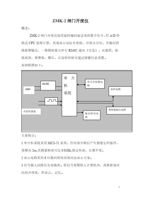
计数仪表中文操作说明书一.设定说明及参数描述1-1最大称量及感量设定说明1)按【累计/保存】键开机,进入称量设置。
2)方式一:按【清除/HI】或【列印/LO】键切换至各个常见称量,按【③/重示】或【扣重/④】键左右移动小数点,按【取样】键选择单位kg或g或lb。
方式二:若常见称量无所需称量,则按【净毛重/设置】键进入自由称量设置,窗口最左边数字闪烁。
按【③/重示】或【扣重/④】键左右移位,按【清除/HI】或【列印/LO】键修改数值或按相应的数字键进行修改;当移动到小数点闪烁时,按【清除/HI】或【列印/LO】键选择小数点的位置。
按【取样】键选择单位kg或g或lb。
修改完成后如果按【累计/保存】键则会保存并进入到感量设置。
按【歸零/ESC】键则会返回至称重状态。
3)称量设置完成后进入感量设置。
4)方式一:按【清除/HI】或【列印/LO】键选择常用感量,按【③/重示】或【扣重/④】键左右移动小数点。
5)方式二:若常见感量无所需感量,则按【净毛重/设置】键进入自由感量设置(按照最小刻度1/2/5原则来设置),窗口最右边数字闪烁。
按【③/重示】或【扣重/④】键左右移位,按【清除/HI】或【列印/LO】键修改数值或按相应的数字键进行修改;当移动到小数点闪烁时,按【清除/HI】或【列印/LO】键选择小数点的位置。
修改完成后如果按【累计/保存】键进入到校正状态。
按【歸零/ESC】键则会取消当前设置,并回到称量设置。
6)感量设置完成后进入校正。
如果按【扣重/④】键则会进入校正,按【歸零/ESC】键则退出校正并返回秤重状态。
1-2功能设定1)按【净毛重/设置】键开机或在称重状态下长按【净毛重/设置】键进入参数设定。
2)按【③/重示】或【扣重/④】键可循环选择参数。
3)按【净毛重/设置】键则进入参数选项。
4)按【③/重示】或【扣重/④】键键循环选择参数选项。
5)按【累计/保存】保存修改内容并返回参数选项或者按【归零/ESC】键不变更设置返回参数选项。

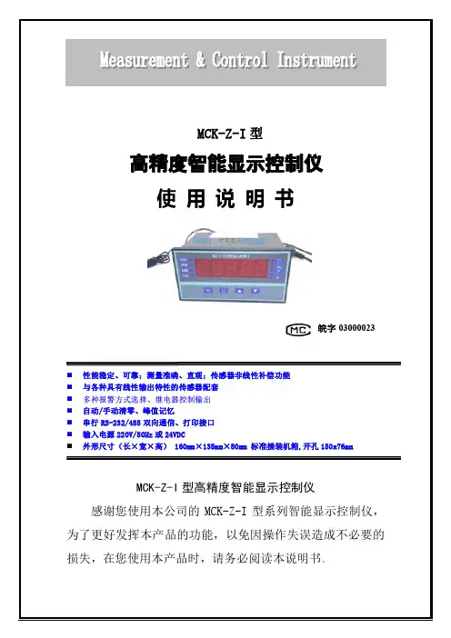
MCK-Z-I型高精度智能显示控制仪使用说明书皖字03000023⏹性能稳定、可靠;测量准确、直观;传感器非线性补偿功能⏹与各种具有线性输出特性的传感器配套⏹⏹自动/手动清零、峰值记忆⏹串行RS-232/485双向通信、打印接口⏹输入电源220V/50Hz或24VDC⏹外形尺寸(长×宽×高) 160mm×135mm×80mm 标准插装机箱,开孔150x76mmMCK-Z-I型高精度智能显示控制仪感谢您使用本公司的MCK-Z-I型系列智能显示控制仪,为了更好发挥本产品的功能,以免因操作失误造成不必要的损失,在您使用本产品时,请务必阅读本说明书。
一、技术参数1、输入方式:mV信号、标准变送信号;2、测量精度:±0.02%(FS)/(23℃±5℃);3、采样速度:10次/秒;80次/秒(订货需说明,默认10次/秒);4、显示方式:5位0.8英寸高亮LED数码管,亮度四级可调;显示范围-19999--99999;5、报警输出:最多四路继电器,每路可选下限、上下限、上下限区间报警;触点容量:(3A/220VAC);订货需要说明,默认两路;6、模拟量输出:0-5V、1-5V、4-20 mA等可选;(订货需说明,默认无)7、通讯接口:标准串行RS-232/485双向接口、多机地址范围0-99;波特率2400-38400bps;(订货需说明,默认无)8、电源:220VAC/50Hz或24VDC可选(默认220VAC);9、外形尺寸:160(L)×125(W)×80(H)标准插装机箱。
二、面板及按键操作说明⏹ 2.1面板说明①---测量值显示窗口;②---报警指示区域;③---单位指示区域;④---按键区。
✧测量值显示窗口:显示实时测量值或峰值;✧报警指示区域:当ALM1-ALM4继电器动作时,对应的指示灯亮;✧单位指示区域:选择好测量单位后,对应的单位指示灯亮;✧按键区:---设置键; ---移位清零键; ---增加键; ---减少键;⏹ 2.2按键操作说明名称内容操作键设置键在测量状态下,按设置键后输入对应的密码进入相关的参数设置,再按该键可进入下一项参数设置,完成相关的组别参数设置后按该键返回移位清零键在测量状态下,按该键实现清零操作;在设置状态下,按该键可实现闪烁位移位增加键 在设置状态下,按增加键可实现数字增加,长按该键可实现数字快速增加 减少键在设置状态下,按增加键可实现数字减少,长按该键可实现数字快速减少三、安装与接线接线端子见下图:四、参数一览及设置该表列出了仪表的基本功能参数和与选配功能相关的参数,与选配功能相关的参数只有该台仪表有相应的选配功能时才会出现。

GCS型光栅数显系统(英文米字管提示)使用说明书恒兴星精密仪器有限公司尊敬的用户:欢迎您使用深圳市恒兴星最新开发液晶英文提示的GCS 光栅数显系统,恒兴星光栅系统广泛用于铣床、磨床、镗床、线切割、车床,它的应用有助于提高生产效率、显示直观、操作方便、精度准确、重复性稳定,是模具制造业、机械加工业、精密测量仪器必不可少的装置。
本系统设置多种智能化功能,如SDM300点记忆、等分圆和椭圆、斜面加工、R的加工8 个面选择、分中功能的用法,还配置了计算器,等等功能,使用起来十分方便。
应用恒兴星的光栅数显系统,不须经过培训,按照英文使用说明书每步提示一看就懂。
最适合刚使用操作的新手,对于熟练得操作者更是得心应手。
要想了解有关的细节请详细阅读使用说明书。
安全注意事项:打开产品包装,取出箱内数显表与电子尺相接,然后插上电源检查显示是否正常。
①开箱后检查外观是否完好,若有故障应立即联系本公司销售部,切勿自行拆卸维修。
②本装置使用110V~220V,50Hz~60Hz的交流电源,电源插头是带有接地脚的三芯电源插头。
三芯电源插座地线一定要接地牢靠。
③用户不可以自行打开机壳修理,表内有很高压电源以免造成人员伤害。
④本机壳是采用ABS工程塑料,不具防爆高温的环境中使用。
⑤平时不用时请关闭电源,可延长本产品使用时间。
⑥在雷雨天气时应关闭或拔掉电源线以免高压雷击电网引起表的电源电压突然猛增高而烧毁表内电源,给用户带来不必要的损失。
日常维护:①每天下班时,清洁时请关闭电源。
②用干布或毛刷擦拭数显表或电子尺防护外壳。
③不能用甲苯或乙醇清洗外壳。
④数显表外壳或显示窗的污迹可用洗衣粉和水搅匀用毛巾扭干水擦拭。
承诺:本公司产品如因用户使用操作不当造成电子尺和数显表的损坏,特别是因碰撞造成产品外观或内部损坏,或自行拆下电子尺限位,造成因超行程把尺撞坏,需本公司维修服务的,本公司要收取适当的材料费和维修费。
面板按键说明GCS-900目录功能项目 (7)清零 (8)输入坐标 (8)公/英制显示 (8)ABS/INC坐标 (9)自动分中 (10)RI(寻找师傅零位) (11)半径/直径 (11)计算器 (11)SDM300组记忆 (12)圆周分孔 (18)椭圆分孔 (21)斜线分孔 (25)圆弧加工 (27)平滑圆弧加工 (35)斜面加工 (39)基本参数 (42)高级用户 (43)光栅线位移传感器 (45)光栅线位移动传感器行程和安装尺寸 (48)安装示图 (49)故障分析与处理 (50)GCS-英文提示光栅数显表,英文辅助显示智能表,采用高科技软件电子技术,功能多、易操作、可靠耐用,使机械加工的必备产品。

K系列可编程数显仪表使用说明书一、概述K系列可编程智能报警变送仪表是在X系列数显电测表基础上增加以下功能和特点:1、显示倍率、通讯地址、波特率等通过面板上按钮可任意设置,使用非常灵活方便。
2、可选择被测量值的变送输出,输出为4—20mA,0—5V,4—12—20mA等可选。
3、带RS-485数字接口,采用标准MODBUS-RTU协议,具备字通讯和字节通讯方式,自带上位机测试软件。
4、使用范围广、组合功能强。
5、具有上下限报警功能,上下限报警允许设定功能,用户可以灵活组合使用以实现某些控制功能。
6、数字校零、数字校调,精度高,性价比极高。
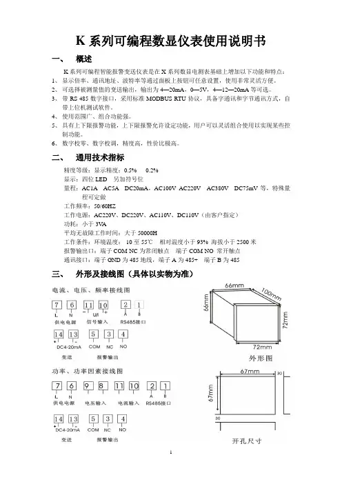
二、通用技术指标精度等级:显示精度:0.5% 0.2%显示:四位LED 另加符号位量程:AC1A AC5A DC20mA,AC100V AC220V AC380V DC75mV等,特殊量程可定做工作频率:50/60HZ工作电源:AC220V、DC220V、AC110V、DC110V(由客户指定)功耗:小于3V A平均无故障工作时间:大于50000H工作条件:环境温度:-10至55℃相对温度小于93% 海拔小于2500米报警输出口:端子COM-NC为常闭触点端子COM-NO 常开触点通讯接口:端子GND为485地线,端子A为485+ 端子B为485-三、外形及接线图(具体以实物为准)四、编程说明仪表共设四个按键,分别为“←”“→”“ MENU””“←”键:左移键,对菜单进行左移动选择,或是对所设定数字进行减功能,在设定大数据时持续按该键可实现快速减功能。
“→”键:右移键,对菜单进行右移动选择,或是对所设定数字进行加功能,在设定大数据时持续按该键可实现快速加功能。
“MENU”键:编程键,用此键可进入编程菜单,或是跳回上一级菜单,忽略操作。
”键:确认键,用于进入下一层菜单或操作确认。
仪表参数设定说明:该仪表采用四键制设定输入,用“MENU“0001”,仪表共有13项设定功能。

V1.0M5产品说明书非常感谢您选用麦克传感器股份有限公司的产品。
为了更好的使用本产品,建议您在使用该产品之前仔细阅读说明书。
1概述本智能数显表仅用输入、输出两条线串连接入4mA~20mA DC变送器回路中,即可将通过的电流量,按设定的范围,线性对应地以十进位数字量显示出来,最大幅值为99999,即5位。
变送器回路电流,既作为显示表的输入信号,也作为显示表的工作电源;面板按键可调零位和满度,操作简单方便,精度高。
此外,显示表采用背光液晶(LCD)显示板,在强光和暗光环境下,都可清楚显示数字,适用性广。
本智能数显表上、下端装有Hirschmann插头、插座,可以串连接入用赫斯曼接口的变送器装置中,做数值显示器用。
2性能指标工作方式:无源4mA~20mA DC内部分辨率:16位AD显示方式:液晶+背光(白色背光)显示范围:-19999~99999温度飘移:<50ppm压降:<3.5V DC采样速率:4次/秒精度:±0.1%极性保护:反极性保护过电流保护:<50mA工作温度:-25℃~70℃储存温度:-40℃~80℃单位选择:25种单位可以选择(压力、温度、高度)3按键功能:移位,菜单选择,功能选择:数字修改,菜单选择,功能选择:功能确认4菜单设置流程5外形结构单位为毫米6电气连接本表表体上方装有赫斯曼圆形阳性插头,接电源、负载电缆,下方有赫斯曼方形阴性插座,可与变送器上的插头插接(见下图)。
电气定义为:1脚:4mA~20mA DC(24VDC+);2脚:4mA~20mA DC(信号+)。
7责任从发货之日起一年内,本公司对因材料和工艺问题造成的有质量缺陷的产品免费更换或维修;对使用过程中非质量原因造成的产品故障,我公司负责维修,仅收取材料成本费。
包装费及运费由用户承担。
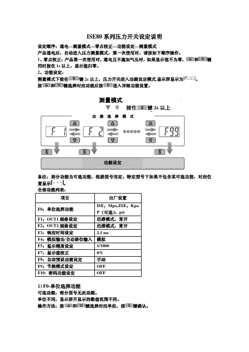
ISE80系列压力开关设定说明设定顺序:通电—测量模式—零点校正—功能设定—测量模式产品通电后,自动进入压力测量模式,第一次使用时,请按如下顺序操作。
1、零点校正:产品第一次使用时,通电且不施加气压时,如果显示值不为零,和键同时按住1s 以上,显示值归零。
2、功能设定:测量模式下按住键2s 以上,压力开关进入功能设定模式,显示屏显示为。
按和键选择对应功能后按进入详细功能设置。
备注:部分功能为可选功能,根据型号而定。
特定型号下如果不包含某可选功能,对应位置显示。
全部功能列表:项目出厂设置 F0:单位选择功能 ISE :Mpa,ZSE :Kpa P (可选):psi F1:OUT1规格设定 迟滞模式,常开 F2:OUT2规格设定 迟滞模式,常开 F3:响应时间设定 2.5 ms F4:模拟输出/自动移位输入 模拟F5:显示精度设定 1/1000 F7:显示值校正 0% F8:自动预设功能设定 手动 F9:节能模式设定 OFF F10: 密码功能设定OFF1) F0-单位选择功能可选功能,部分型号无此功能。
单位不同,显示屏开显示的数值范围不同。
操作方法:按和键选择对应单位,按键确认。
按住键2s 以上功 能 选 择 模 式功能设定测量模式按键进入单位选择模式按和键选择对应单位交替显示按键完成设定返回到功能选择模式,屏幕显示F0F0-单位选择功能设定完成2)F1-OUT1规格设定方法此部分可设置输出类别(迟滞型/比较型)和输出模式(常开/常闭)设定。
输出模式出厂时默认设置常开型迟滞模式(出厂时默认设置)输出迟滞(H-1)压力比较模式(也称窗口比较模式)输出迟滞(H1)迟滞(H1)压力迟滞模式(出厂时默认设置)输出迟滞(H-1)压力比较模式(也称窗口比较模式)输出迟滞(H1)迟滞(H1)压力常闭型功能选择模式下按和至屏幕显示,然后按进入OUT1规格设定。
压力设定状态:此状态下设定压力开关输出的ON/OFF 点。
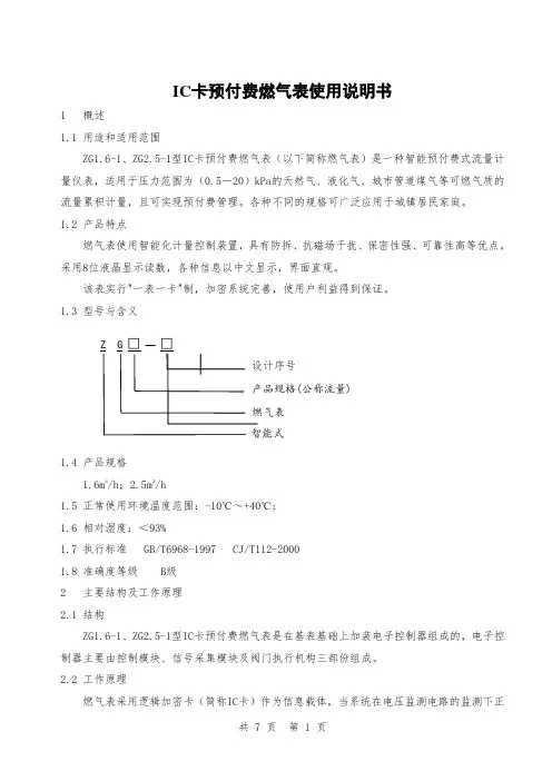
IC 卡预付费燃气表使用说明书1 概述1.1 用途和适用范围ZG1.6-1、ZG2.5-1型IC 卡预付费燃气表(以下简称燃气表)是一种智能预付费式流量计量仪表,适用于压力范围为(0.5-20)kPa 的天然气、液化气、城市管道煤气等可燃气质的流量累积计量,且可实现预付费管理。
各种不同的规格可广泛应用于城镇居民家庭。
1.2 产品特点燃气表使用智能化计量控制装置,具有防拆、抗磁场干扰、保密性强、可靠性高等优点。
采用8位液晶显示读数,各种信息以中文显示,界面直观。
该表实行"一表一卡"制,加密系统完善,使用户利益得到保证。
1.3 型号与含义1.4 产品规格 1.6m 3/h ;2.5m 3/h1.5 正常使用环境温度范围:-10℃~+40℃; 1.6 相对湿度:<93%1.7 执行标准 GB/T6968-1997 CJ/T112-2000 1.8 准确度等级 B 级 2 主要结构及工作原理2.1 结构ZG1.6-1、ZG2.5-1型IC 卡预付费燃气表是在基表基础上加装电子控制器组成的,电子控制器主要由控制模块、信号采集模块及阀门执行机构三部份组成。
2.2 工作原理燃气表采用逻辑加密卡(简称IC 卡)作为信息载体,当系统在电压监测电路的监测下正(公称流量)常工作时,控制模块从IC卡中读入数据,并进行数据交换,将燃气表的相关气量信息和工作状态等信息写入IC卡,并通过IC卡反馈到售气管理系统中。
当用气时,控制模块接收来自采集模块的信号,对表内的气量信息作相应的计量处理,当表内剩余气量降至0时,控制模块发出关闭阀门的指令以切断气路,阻止用气,直到用户重新向燃气表输入所购的气量时,才可恢复用气,从而实现预付费管理。
当控制模块接收到磁场干扰、过流等信号时,则会发出关阀指令以关断气路,并将燃气表相应的状态信息送到LCD显示,当用户插入IC卡时,控制模块会将这些状态信息写入IC卡,当再次购气时,售气管理系统会读取IC卡中的这些状态信息并存储到数据库,实现信息的反馈。

User Manual&Guide智能数显压力表使用说明书杭州美控自动化技术有限公司U-P3.1-MKCN1第1版前言前言●感谢您购买我公司产品!●本手册是关于产品的功能、操作方法和故障处理方法等的说明书。
●在操作之前请仔细阅读本手册,正确使用产品。
●在您阅读完后,请妥善保管在便于随时取阅的地方,以便操作时参照。
注意●本手册内容如因功能升级等有修改时,恕不通知。
●本手册内容我们力求正确无误,如果您发现有误,请与我公司联系。
版本U-P3.1-MKCN1第1版2018年5月前言确认包装内容开箱之后请先确认产品和附件,一旦产品有误、数量不对或外观受损,请与我公司联系。
产品清单序号物品名称数量1数显压力表1台2说明书1本3合格证1份47号电池(AAA)2节使用注意事项1、在不需要使用背光的情况下,请关闭背光,以延长电池使用时间。
2、长期不使用产品的情况下,请取出电池。
3、如需对产品校准,请与我公司联系,非专业人士不得进行校准。
目录目录一、产品简介 (1)二、技术参数 (3)三、显示与按键 (4)四、压力表校准 (6)五、峰值保存功能 (7)六、尺寸结构与安装 (8)七、注意事项 (10)八、质保及售后服务 (11)九、产品选型 (12)一、产品简介一、产品简介Y290型高精度数显压力表,内置高精度压力传感器,能够准确的实时显示压力,并且具有精度高,长期稳定性好的特点。
本产品配备段式液晶显示屏,具有清零、背光、开关机、单位切换和低电压报警等多项功能,操作简单,安装方便。
本产品采用优质304不锈钢壳体和接头,抗震性好,能够测量气体、水、油等对不锈钢无腐蚀的介质。
本产品适合于便携式压力测量、设备配套、校验设备等压力测量应用。
产品特点●一键清零,使用方便。
●优质304不锈钢壳体和接头,抗震耐用。
●多种测量单位,一键切换,使用更省心。
●具有温度补偿,温度系数小,测量更精准。
-1-一、产品简介●最大1.1倍量程过载显示,更有峰值记录功能,使用更可靠。
MCL-2微机磁力仪说明书河北省地矿电子技术开发应用研究所目录一、产品特点 (1)二、主要技术指标 (2)三、仪器组成 (3)四、工作原理 (3)五、仪器菜单结构说明 (4)六、简单测量方式 (9)七、数据存储测量方式 (10)八、数据传输软件使用 (11)九、仪器的维护及注意事项 (12)附录:GRAPHER软件的使用 (14)感谢您使用MCL-2微机磁力仪河北省地矿电子技术开发应用研究所有着三十多年研制和生产地质仪器的悠久历史。
有十项研究成果获地矿部或河北省科技进步二等奖或三等奖,生产的地质仪器销往国内外各地矿单位,有较好的声誉。
MCL-2微机磁力仪是我所在MCL-1A型数字磁力仪基础上新研制成功的,它是根据磁通门原理利用计算机智能控制的新型磁力仪,用于铁矿勘察及其地下铁质埋藏物。
由于该磁力仪操作十分简单,几分钟即能学会使用,大屏幕液晶可直接显示被测的磁场强度 nT(伽码),同时显示温度,日期,电量(仪器电池),故特别适合于初学者使用。
由于该磁力仪内置计算机,具有自动线性校正,自动温度校正,24位高精度A/D转换器,可测量高达8万纳特强磁场,大屏幕显示器可显示磁场强度曲线,与电脑连接可进一步作数据处理和解释推断,故该磁力仪同样适用于专业物探、地质人员使用,是一种操作简便,具有较高分辨率和较高精度的磁力仪,性价比很高。
一、产品特点1.采用微处理器控制,能自动存储该测量点的磁场垂直分量、温度、时间,无需人工补偿,具有温度自动补偿功能。
2.大屏幕显示,全中文界面,自动显示磁场强度曲线,操作简单。
3.采用24位A/D转换器,分辨率高,测量范围宽。
4.自动电量显示。
5.背光显示,方便夜间操作。
二、主要技术指标。
测量范围:0-80000nT分辨率:1nT存储量: 5120个点探头:硅油阻尼,转向差≤±10nT。
显示:160×128液晶,带背光。
电源: 1.3AH铅酸充电电池。
整机功耗: 80mA~110mA。
高性能的数字显示报警仪使用说明z 主要技术指标:1、显示范围:-1999~9999,小数点位置可设置。
2、测量及变送输出准确度:±0.2%FS±1字;±0.1%FS±1字(需特殊订制。
3、输入信号:热电偶: K、E、S、B、J、T、R、N;冷端温度自动补偿范围 0~50℃,补偿准确度±1℃。
热电阻:Pt100、Cu100、Cu50、BA2、BA1;引线电阻补偿范围≤15Ω。
直流电压:0~20mV、0~75mV、0~200mV、0~5V、1~5V;0~10V(订货时需指定,与其他信号不兼容。
直流电流:0~10mA、4~20mA 。
线性电阻:0~400Ω(远传压力表。
频率:0.1Hz-10KHz。
(该功能需单独指定,与其它信号不兼容输入。
4、模拟输入阻抗:电流信号Ri=100Ω;电压信号Ri=500KΩ。
5、模拟输出负载能力:电流信号:4~20mA输出时Ro≤750Ω;0~10mA输出时Ro≤1.5KΩ。
电压信号:要求外接仪表的输入阻抗Ri≥250KΩ, 否则不保证连接外部仪表后的输出准确度及线性度。
6、配电输出:DC24±1V 30mA,过流自动保护。
7、报警方式:单回路可对应四个报警点,双回路仪表每回路对应 2个报警点。
8、通讯方式:RS232(10m或 RS485(1000m 9、使用环境:环境温度:-10~55℃,环境湿度:10~90%RH。
10、耐压强度: 输入/输出/电源/通讯≥1000V.AC 1分钟。
11、绝缘阻抗: 输入/输出/电源/通讯≥100MΩ。
12、电源:开关电源:交流:85~265V,频率: 50Hz±2Hz; (推荐使用线性电源:交流:220V±10V,频率: 50Hz±2Hz; (变压器电源,不推荐使用直流电源:DC 24V (适用范围 16V-28V13、功耗:<4W。
多功能电力监测仪使用手册版本:杭州正普科技有限公司使用前必读在您使用本产品之前,请务必仔细阅读此使用手册内容,正确按照用户手册指导操作,这会有助于您更好地使用本产品,并有助于解决现场出现的各种问题。
1、监测仪在施加工作电源之前,务必确保工作电源在仪表规定范围之内;2、现场安装使用时,电流输入端子严禁开路,电压输入端子严禁短路;3、通讯端子(RS485)严禁施加高压;4、使用时仪表接线方式务必与内部系统设置方式一致;5、与后台通讯时,仪表通讯参数务必与后台一致;不能带电拔插通信接口;6、本手册中的信息如有变动,恕不另行通知;我公司自始至终本着“质量第一服务第一”的宗旨,将以优质的产品、优良的服务奉献给国内外用户!●使用前请仔细阅读本用户使用手册●请注意妥善保存目录一、概述-------------------------------------------------- 1二、型号定义---------------------------------------------- 1三、尺寸对照表-------------------------------------------- 1四、型号与功能对照表-------------------------------------- 2五、技术指标---------------------------------------------- 3六、外形及安装尺寸---------------------------------------- 4七、接线图------------------------------------------------ 6八、操作说明----------------------------7(RS485通讯规约、CT/PT设置、开关量操作、变送输出操作)一、概述多功能电力监测仪具有对电网中电流、电压、频率、有功功率、无功功率、视在功率、电能、功率因数等进行同时测量的功能。
1NOTE: This module must be “included in the Network” only where it will be permanently installed. The proper operation of this node in the mesh network is dependent on it knowing its location with respect to other nodes. You cannot “test bench” confi gure this module.WTOOZ-1 WALL MOUNTED TRANSMITTERLinear’s family of Z-Wave certifi ed wireless lighting controls (switches,dimmers, outlets and plug-in modules) brings a new level of intelligent wireless capability to commercial and residential environments.The Z-Wave wireless protocol is an international wireless standard for remote home automation, security and other applications. Embedded in each device, the Z-Wave smart chip enables two-way RF communication among hundreds of Z-Wave enabled devices, allowing products and services from multiple manufacturers to work seamlessly.Linear Z-Wave products are easy to install, and allow dealers to create an integrated wireless network with nearly limitless expansion and interoperability with security and health monitoring systems, energy management, home entertainment, appliances, and more.INSTALLATIONDANGER! SHOCK HAZARD. Read and understand these instructions before installing. This device is intended for installation in accordance with the National Electric code and local regulations in the United States, or the Canadian Electrical Code and local regulations in Canada. It is recommended that a qualifi ed electrician perform this installation. Retain instructions for future use. With power off, wire this WT00Z-1 according to the diagram shown above. If more than one WT00Z-1 is to be installed in a wall box, scored tabs on the side can be broken off by bending back and forth with pliers, to accommodate proper fi t. Apply power when completed. Refer to your Controller operating instructions on how to include this module in the RF networkINCLUDING WT00Z-1 TO THE NETWORKSTEP 1. Prepare the Controller to include a unit to the network by adding it to a group (method of adding a node to the network). Refer to controller instructions.STEP 2. The WT00Z-1 must be in its permanently installed location. Tap either the top or bottom of the WT00Z-1 once.STEP 3. You should see an indication on your Controller that the “device was included” in the network.NOTE: If you have trouble adding the WT00Z-1 to a group it may be that the Home ID and Node ID were not cleared from it after testing. Y ou must fi rst “RESET UNIT” with your controlle r to re move it from the network. Although adding it to a group includes it in the network, re moving it from a group doe s not re move it from the ne twork. If removed from a group, it functions as a repeater (only). “RESET UNIT”removes it completely from the network.WT00Z-1Radio Frequency (RF) Controlled, 120 VAC, Wall MountedTransmitter, Series 300SUPPLIED WITH DECORATIVE SWITCH PLATEOF PLASTICOPERATIONBefore you can control Z-Wave devices you must associate the devices you want to control from the WT00Z-1.Turning Z-Wave devices On or Off1. Tap the top of the paddle to turn On Z-Wave devices.2. Tap the bottom of the paddle to turn Off Z-Wave devices.The LED on the WT00Z-1 will indicate the status of the devices you are controlling. The LED on the WT00Z-1 will fl icker when it is transmitting commands to any of the four groups. This can be changed. See “LED Transmission Indication”.Dimming and Brightening1. Press and hold the top of the paddle to brighten Z-Wave enableddimmers.2. Press and hold the bottom of the paddle to dim Z-Wave enableddimmers.Associating Z-Wave devices to control from the WT00Z-1 Refer to your controllers instructions to fi nd out how to associate Z-Wave devices. You can associate another Z-Wave device into any or all of the 4 available groups in the WT00Z-1. The four groups are described below: Group 1Nodes in this group are turned ON by tapping the top of the paddle or OFF by tapping the bottom of the paddle. Nodes associated into this group are dimmed by pressing and holding the bottom of the paddle until the desired dim level is reached or brightened by pressing and holding the top of the paddle until the desired level is reached.The LED on the WT00Z-1 will indicate the status of this group ONLY. NOTE: Associating nodes into group 2 or 3 will cause a very slight delay before the command is transmitted to group 1.Group 2Nodes in this group are turned ON by tapping the top of the paddle twice or OFF by tapping the bottom of the paddle twice. Nodes associated into this group are dimmed by tapping the bottom of the paddle once and then pressing and holding the bottom of the paddle until the desired dim level is reached or brightened by tapping the top of the paddle once then pressing and holding the top of the paddle until the desire level is reached.Group 3Nodes in this group are turned ON by tapping the top of the paddle three times or OFF by tapping the bottom of the paddle three times. Nodes associated into this group are dimmed by tapping the bottom of the paddle twice and then pressing and holding the bottom of the paddle until the desired dim level is reached or brightened by tapping the top of the paddle twice then pressing and holding the top of the paddle until the desired level is reached.Group 4Nodes in this group are turned ON or OFF or set to a specifi c dim level when the WT00Z-1 is controlled remotely. You can place up to 5 nodes in each group. If controlling dimmers, for best results, associate the dimmers into the group fi rst.CONFIGURATIONThe WT00Z-1 supports the Confi guration command.The WT00Z-1 simulates the operation of a dimmer. Using confi guration commands you can adjust the dimming parameters as though it were a dimmer. The WT00Z-1 can be confi gured to operate slightly differently than how it works when you first install it. Using the configuration command you can change operational characteristics.Set Ignore Start Level Bit When Transmitting Dim Commands The WT00Z-1 can send Dim commands to Z-Wave enabled dimmers. The Dim command has a start level embedded in it. A dimmer receiving this command will start dimming from that start level. However, the command can be sent so that the dimmer ignores the start level and instead starts dimming from its current level. By default, the WT00Z-1 sends the command so that the dimmer will start dimming from its current dim level rather than the start level embedded in the command. To change this, simply set the confi guration parameter to 0.• Parameter No: 1• Length: 1 Byte• Valid Values = 0 or 1 (default 1)NOTE: Any ACT Z-Wave enabled dimmers have the confi guration option to ignore the start level no matter how you confi gure the WT00Z-1 Suspend Group 4You may wish to disable transmitting commands to Z-Wave devices that are in Group 4 without “un-associating” those devices from the group. Setting parameter 2 to the value of 1 will stop the WT00Z-1 from transmitting to devices that are “associated” into Group 4.• Parameter No: 2• Length: 1 Byte• Valid Values = 0 or 1 (default 0)Night LightThe LED on the WT00Z-1 will by default, turn ON when the status of the devices in Group 1 is ON. To make the LED turn ON when the status of Group 1 is OFF set this parameter to a value of 1.• Parameter No: 3• Length: 1 Byte• Valid Values = 0 or 1 (default 0)Invert SwitchTo change the top of the transmitter to OFF and the bottom of the transmitter to ON, set parameter 4 to 1. To change back to original settings, set this parameter to the value of 0.• Parameter No: 4• Length: 1 Byte• Valid Values = 0 or 1 (default 0)Ignore Start Level When Receiving Dim CommandsThe WT00Z-1 can send Dim commands to Z-Wave enabled dimmers. The Dim command has a start level embedded in it. A dimmer receiving this command will start dimming from that start level. However, the command can be sent so that the dimmer ignores the start level and instead start dimming from its current level. By default, the WT00Z-1 sends the command so that the dimmer will start dimming from its current dim level rather then the start level embedded in the command. To change this, simply set the confi guration parameter to 0.• Parameter No: 5• Length: 1 Byte• Valid Values = 0 or 1 (default 1)NOTE: This only affects a level that is reported or possibly sent by the WT00Z-1 since the WT00Z-1 does not control a load.2Adjusting Dim RateFor example: There are 3 sets of parameters that can adjust the dimming rate of the WT00Z-1.1. One set to control how fast the dim rate is when the dimmer receivesa Z-Wave command excluding ALL ON or ALL OFF command.2. One set to control how fast the dim rate is when the dimmer islocally controlled.3. One set to control how fast the dim rate is when the dimmer receivesan ALL ON or ALL OFF command.These values can be changed instantly to allow various scenes and effects. The first of these parameters is the “dim step” (dim rate) parameter. It can be set to a value of 1 to 99. This value indicates how many levels the dimmer will change when the timer (discussed below) expires. The second parameter is the timing (how fast the dim rate) parameter. It can be set to a value of 1 to 255. This value indicates in 10 millisecond resolution, how often the dim level will change. For example, if you set this parameter to 1, then every 10mS the dim level will change. If you set it to 255, then every 2.55 seconds the dim level will change. With the combination of the two parameters that can control the dim rate, the dimmer can be adjusted to dim from maximum to minimum or minimum to maximum at various speeds between 10 millisecond and 252.45 seconds (over 4.25 minutes).• Parameter 7-12• Length: 1 Byte• Valid Values: (See next)NOTE: that this only affects a level that is reported or possibly sent by the WT00Z-1 since the WT00Z-1 does not control a load.On/Off Command dim rate (excluding ALL ON/ALL OFF commands)• Parameter 7• Dim step Parameter (default = 3)• Valid Values: 1-99• Parameter 8• Dim timer Parameter (default =10)• Valid Values: 1-255Local Control dim rate• Parameter 9• Dim step Parameter (default = 3)• Valid Values: 1-99• Parameter 10• Dim timer Parameter (default = 10)• Valid Values: 1-255ALL ON/ALL OFF dim rate• Parameter 11• Dim step Parameter (default = 3)• Valid Values: 1-99• Parameter 12• Dim timer Parameter (default = 10)• Valid Values: 1-255Disable Group 4 During a Dim CommandAfter the WT00Z-1 is commanded to stop dimming when dimming because of the DIM START command, it will then command the Z-Wave devices that are in Group 4 to its new level. To prevent the WT00Z-1 from commanding the Z-Wave devices in Group 4 during this particular occurrence, set Parameter 13 to the value of 1.• Parameter 13• Length: 1 Byte• Valid Values = 0 or 1 (default 0)NOTE: This only affects a level that is reported or possibly sent by the WT00Z-1 since the WT00Z-1 does not control a load.Enable Shade Control Group 1The WT00Z-1 can control shade control devices via its group 1 if this confi guration parameter is set to 1.• Parameter 16• Length: 1 Byte• Valid Values = 0 or 1 (default 0)Enable Shade Control Group 2The WT00Z-1 can control shade control devices via its group 2 if this confi guration parameter is set to 1.• Parameter 14• Length: 1 Byte• Valid Values: 0 or 1 (default 0)Enable Shade Control Group 3The WT00Z-1 can control shade control devices via its group 3 if this confi guration parameter is set to 1.• Parameter 15• Length: 1 Byte• Valid Values: 0 or 1 (default 0)LED Transmission IndicationThe WT00Z-1 will fl icker its LED when it is transmitting to any of its 4 groups. This fl ickering can be set to not fl icker at all (set to 0), to fl icker the entire time it is transmitting (set to 1), or to fl icker for only 1 second when it begins transmitting (set to 2). By default, the WT00Z-1 is set to fl icker for only 1 second.• Parameter 19• Length: 1 Byte• Valid Values = 0 , 1, 2 (default 2)Poll: MinutesThe WT00Z-1 will poll the fi rst node in Group 1 in order to keep itself synchronized with the group if this confi guration parameter is set to 1. How often it will poll is confi gured using this parameter.• Parameter 20• Length: 1 Byte• Valid Values = 1 through 255 (default: 2)Poll First Node in Group 1The WT00Z-1 will poll the fi rst node in Group 1 in order to keep itself synchronized with the group if this confi guration parameter is set to 1.• Parameter 21• Length: 1 Byte• Valid Values = 0 , 1 (default 0)Each Confi guration Parameter can be set to its default setting by setting the default bit in the Confi guration Set command. See your controller’s instructions on how to do this (and if it supports it). All Configuration commands will be reset to their default state when the WT00Z-1 is “reset” thus removing it from the Z-Wave network. SPECIFICATIONSPower:120 VAC, 60 HzSignal:(Frequency) 908.42 MHzRange:Up to 100 feet line of sight between the Controllerand /or the closest EGC Receiver Module INTEROPERABILITY WITH Z-WAVE DEVICESA Z-Wave™ network can integrate devices of various classes, and these devices can be made by different manufacturers. The WT00Z-1 can be incorporated into existing Z-Wave™ networks. The top or bottom of the WT00Z-1 switch paddle can be used to carry out inclusion (adding to the network by adding to a group), association (operate simultaneously with other nodes), exclusion (remove from a group) or reset (remove from the network). Controllers can be replicated in order to provide operation from other locations.34Copyright © 2013 Linear LLC 234730 AX2 P1774 X3REGULATORY INFORMATIONThe WT00Z-1 is certifi ed to comply with applicable FCC and IC rules and regulations governing RF and EMI emissions. This device complies with part 15 of the FCC Rules. Operation is subject to the following two conditions: (1) This device may not cause harmful interference, and (2) This device must accept any interference received, including interference that may cause undesired operation.FCC NOTICENote: This equipment has been tested and found to comply with the limits for a Class B digital device, pursuant to part 15 of the FCC Rules. These limits are designed to provide reasonable protection against harmful interference in a residential installation. This equipment generates, uses, and can radiate radio frequency energy and, if not installed and used in accordance with the instructions may cause harmful interference to radio communications. However, there is no guarantee that interference will not occur in a particular installation. If this equipment does cause harmful interference to radio or television reception, which can be determined by turning the equipment off and on, the user is encouraged to try to correct the interference by one or more of the following measures:• Reorient or relocate the receiving antenna.• Increase the separation between the equipment and receiver• Connect the equipment into an outlet on a circuit different from that to which the receiver is connected• Consult the dealer or an experienced radio/TV technician to help.• Changes or modifications not expressly approved by the party responsible for compliance could void the user’s authority to operate the equipmentIC NOTICEThis Class B digital apparatus complies with Canadian ICES-003Cet appareil numérique de la classe B est conforme à la norme NMB-003 du Canada. L e présent appareil est conforme aux CNR d’Industrie Canada applicables aux appareils radio exempts de licence. L ’exploitation est autorisée aux deux conditions suivantes : (1) l’appareil ne doit pas produire de brouillage, et (2) l’utilisateur de l’appareil doit accepter tout brouillage radioélectrique subi, même si le brouillage est susceptible d’en compromettre le fonctionnement.Cet appareil numérique de la classe B est conforme à la norme NMB-003 du Canada. Operation is subject to the following two conditions: (1) this device may not cause interference, and (2) this device must accept any interference, including interference that may cause undesired operation of the device.WARRANTYThis L inear product is warranted against defects in material and workmanship for twelve (12) months. This warranty extends only to wholesale customers who buy direct from Linear or through Linear’s normal distribution channels. L inear does not warrant this product to consumers. Consumers should inquire from their selling dealer as to the nature of the dealer’s warranty, if any. There are no obligations or liabilities on the part of Linear Corporation for consequential damages arising out of or in connection with use or performance of this product or other indirect damages with respect to loss of property, revenue, or profi t, or cost of removal, installation, or reinstallation. All implied warranties, including implied warranties for merchantability and implied warranties for fi tness, are valid only until Warranty Expiration Date as labeled on the product. This Linear LLC Warranty is in lieu of all other warranties express or implied.All products returned for warranty service require a Return Product Authorization Number (RPA#). Contact L inear Technical Services at 1-800-421-1587 for an RPA# and other important details.IMPORTANT !Linear radio controls provide a reliable communications link and fi ll an important need in portable wireless signaling. However, there are some limitations which must be observed.• For U.S. installations only: The radios are required to comply with FCC Rules and Regulations as Part 15 devices. As such, they have limited transmitter power and therefore limited range.• A receiver cannot respond to more than one transmitted signal at a time and may be blocked by radio signals that occur on or near their operating frequencies, regardless of code settings.• Changes or modifications to the device may void FCC compliance.• Infrequently used radio links should be tested regularly to protect against undetected interference or fault.• A general knowledge of radio and its vagaries should be gained prior to acting as a wholesale distributor or dealer, and these facts should be communicated to the ultimate users.。
sick数显压力表说明书一、sick数显压力表的启动与停止用root用户启/停需要root用户包含在sick数显压力表m组中。
1、sick数显压力表的启动strsick数显压力表mQMgrName如果启动默认队列管理器,strsick数显压力表m后可以忽略队列管理器名称。
在意外情况停止队列管理器后,启动可能会失败,此时可以检查上次停止后是否有IPC资源未释放,若有请予以删除,删除方法参考下面的“C、清理所有残留在系统内部的信号灯和共享内存”。
2、sick数显压力表的关闭一般情况下,我们使用“endsick数显压力表m-iQMgrName”来停止sick数显压力表,如果停止失败,可以使用如下步骤:步骤1:endsick数显压力表m-pQMgrName,如果停不掉,继续步骤2:杀死有关进程,清理残留在系统内部的信号灯和共享内存A、找到队列管理器程序进程ps-ef|grepQMgrNameB、使用kill命令终止1>中找到的程序进程,无法停止的进程可以用kill-9来终止,终止进程的顺序如下(不存在的进程可以忽略):killasick数显压力表pcsea命令服务器killasick数显压力表hasmx记录器killasick数显压力表harmx日志格式化器(仅LINEAR日志)killasick数显压力表zllp0检查点处理器killasick数显压力表zlaa0队列管理器代理killasick数显压力表zxma0处理控制器killasick数显压力表rrmfa库进程(用于群集)C、清理所有残留在系统内部的信号灯和共享内存(其属主和组均为sick数显压力表m)ipcs-s|grepsick数显压力表m|awk'{print$2}'|xargs-iipcrm-s{}ipcs-m|grepsick数显压力表m|awk'{print$2}'|xargs-iipcrm-m{}二、sick数显压力表运行状态查看与常用操作1、查看队列管理器运行状态对sick数显压力表5、2或以上版本,执行如下命令检查队列管理器运行状态:dspsick 数显压力表显示结果中QMNAME表示sick数显压力表队列管理器的名称,STATUS表示当前运行状态。