OSRAM灯珠规格书Spec SIRIUS HRI 330W XL
- 格式:pdf
- 大小:834.49 KB
- 文档页数:29
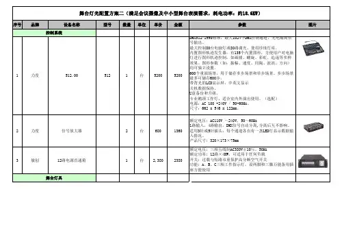
序号品牌设备名称型号数量单位单价金额参数图片1力度512.005121台52005200DMX512/1990标准,最大1024个DMX控制通道,光电隔离信号输出。
最大控制80台电脑灯或80路调光,使用珍珠灯库。
内置图形轨迹发生器,有135个内置图形,方便用户对电脑灯进行图形轨迹控制,如画圆、螺旋、彩虹、追逐等多种效果。
图形参数(如:振幅、速度、间隔、波浪、方向)均可独立设置。
600个重演场景,用于储存多步场景和单步场景。
多步场景最多可储存600步。
带背光的LCD显示屏,中英文显示关机数据保持。
U盘备份和升级。
专业鹅颈工作灯,适合室内外演出使用。
(选配)电源:AC 100 -240V / 50-60Hz。
尺寸:662 x 546 x 122mm。
2力度信号放大器2台6801360额定电压: AC110V ~240V, 50~60Hz1路输入,4路输出。
DMX信号自动分离,分离后互不影响。
适用3针或5针插头;每个通道各自有一盏LED灯显示数据输入情况。
产品尺寸: 320×173×75mm3敏创12路电源直通箱1台2,3802380额定电压: 三相五线制AC380V±10%,50Hz额定功率: 12路×4KW,可适用于任何负载开关: 过载与短路双重保护高分断空气开关功能: A、B、C三相工作指示灯,设两脚和三脚万能备用插座方便使用舞台灯光配置方案二(满足会议摄像及中小型舞台表演需求,耗电功率:约18.6KW)控制系统舞台灯具1nightSun夜太阳LED多功能会议及染色灯(面光)SPC050K16台1,28020,480额定电压:AC100~240V/50~60Hz,额定功率:180W灯珠数量:84颗3W(R12/ G12/B/12/W12/A36)透镜:RGBW25°、A45°通道:9/5通道功能特点:具有会议+演娱双重功能。
会议时,暖白光线均匀铺光,风机处于静止状态,无噪音;演出或娱乐时,RGB全彩染色,风机随之启动,促进散热,延长LED灯珠寿命,全彩变换绝伦,可结合冷暖白光综合应用。
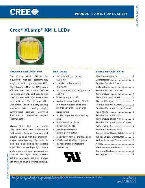
CLD-DS33 Rev 8BProduct family data sheetcree ® Xlamp ® Xm-l ledsW .C R e e .C O M /X L A M PProduct descriPtionThe XLamp XM-L LeD is the industry’s highest performance, single-die white lighting-class LeD. The XLamp XM-L is 20% more efficient than the XLamp XP-G at the same current, and can deliver 1000 lumens with 100 lumens per watt efficacy. The XLamp XM-L LeD offers Cree’s industry-leading features: wide viewing angle, symmetrical package, unlimited floor life and electrically neutral thermal path.XLamp XM-L LeDs can enable LeD light into new applications that require tens of thousands of lumens, such as high bay and high-output area lighting. The XM-L isalso the ideal choice for lighting applications where high light output and maximum efficacy are required, such as LeD light bulbs, outdoor lighting, portable lighting, indoor lighting and solar-powered lighting.features• Maximum drive current: 3000 mA• Low thermal resistance: 2.5 °C/W• Maximum junction temperature: 150 °C• viewing angle: 125°• Available in cool white, 80-CRI minimum neutral white and 80-CRI, 85-CRI and 90-CRI warm white• ANSI-compatible chromaticity bins• Unlimited floor life at ≤ 30 ºC/85% RH • Reflow solderable - JeDeC J-STD-020C• electrically neutral thermal path • RoHS- and REACh-compliant • UL-recognized component (e349212)table of contentsFlux Characteristics ....................2Characteristics ..........................3Relative Spectral PowerDistribution...............................3Relative Flux vs. JunctionTemperature .............................4electrical Characteristics .............4Thermal Design .........................5Relative Flux vs. Current ............5Relative Chromaticity vs. Current (Cool White) .............................6Relative Chromaticity vs.Temperature (Cool White) ...........6Relative Chromaticity vs. Current (Warm White) ...........................7Relative Chromaticity vs.Temperature (Warm White) .........7Typical Spatial Distribution ..........8Reflow Soldering Characteristics ..9Notes ......................................10Mechanical Dimensions..............11Tape and Reel ..........................12Packaging .. (13)fluX characteristics (t= 25 °c)JThe following table provides several base order codes for XLamp XM-L LeDs. It is important to note that the base order codes listed here are a subset of the total available order codes for the product family. For more order codes, as well as a complete description of the order-code nomenclature, please consult the XLamp XM-L Binning and Labeling document.Notes:• Cree maintains a tolerance of ± 7% on flux and power measurements, ±0.005 on chromaticity (CCx, CCy) measurements and ± 2 on CRI measurements.• Typical CRI for Cool White (5000 K – 8300 K CCT) is 65.• Typical CRI for Neutral White (3700 K – 5000 K CCT) is 75.• Typical CRI for Warm White (2600 K – 3700 K CCT) is 80.• Minimum CRI for 80-CRI White is 80.• Minimum CRI for 85-CRI White is 85.• Minimum CRI for 90-CRI White is 90.* Calculated flux values are for reference only.characteristicsrelative sPectral Power distributionrelative fluX vs. Junction temPerature (i f = 700 ma)electrical characteristics (t J= 25 °c)thermal desiGnThe maximum forward current is determined by the thermal resistance between the LeD junction and ambient. It is crucial for the end product to be designed in a manner that minimizes the thermal resistance from the solder point to ambient in order to optimize lamp life and optical characteristics.relative fluX vs. current (tJ = 25 °c)relative chromaticity vs. current (cool white)Cool Whiterelative chromaticity vs. temPerature (cool white) Cool Whiterelative chromaticity vs. current (warm white)Warm Whiterelative chromaticity vs. temPerature (warm white) Warm WhitetyPical sPatial distributionreflow solderinG characteristicsIn testing, Cree has found XLamp XM-L LeDs to be compatible with JeDeC J-STD-020C, using the parameters listed below. As a general guideline, Cree recommends that users follow the recommended soldering profile provided by the manufacturer of solder paste used.Note that this general guideline may not apply to all PCB designs and configurations of reflow soldering equipment.Note: All temperatures refer to the topside of the package, measured on the package body surface.noteslumen maintenance ProjectionsCree now uses standardized IeS LM-80-08 and TM-21-11 methods for collecting long-term data and extrapolating LeD lumen maintenance. For information on the specific LM-80 data sets available for this LED, refer to the public LM-80 results document at /xlamp_app_notes/LM80_results.Please read the XLamp Long-Term Lumen Maintenance application note at /xlamp_app_notes/lumen_ maintenance for more details on Cree’s lumen maintenance testing and forecasting. Please read the XLamp Thermal Management application note at /xlamp_app_notes/thermal_management for details on how thermal design, ambient temperature, and drive current affect the LeD junction temperature.moisture sensitivityIn testing, Cree has found XLamp XM-L LEDs to have unlimited floor life in conditions ≤30 ºC/85% relative humidity (RH). Moisture testing included a 168-hour soak at 85 ºC/85% RH followed by 3 reflow cycles, with visual and electrical inspections at each stage.Cree recommends keeping XLamp LeDs in their sealed moisture-barrier packaging until immediately prior to use. Cree also recommends returning any unused LeDS to the resealable moisture-barrier bag and closing the bag immediately after use.rohs complianceThe levels of RoHS restricted materials in this product are below the maximum concentration values (also referred to as the threshold limits) permitted for such substances, or are used in an exempted application, in accordance with eU Directive 2011/65/EC (RoHS2), as amended through June 8, 2011. RoHS Declarations for this product can be obtain from your Cree representative or obtained from the Product ecology section of .reach complianceREACh substances of high concern (SVHCs) information is available for this product. Since the European Chemical Agency (ECHA) has published notices of their intent to frequently revise the SVHC listing for the foreseeable future, please contact a Cree representative to insure you get the most up-to-date REACh Declaration. Historical REACh banned substance information (substances restricted or banned in the eU prior to 2010) is also available upon request.ul recognized componentLevel 4 enclosure consideration. The LED package or a portion thereof has been investigated as a fire and electrical enclosure per ANSI/UL 8750.vision advisory claimWARNING: Do not look at exposed lamp in operation. Eye injury can result. See the LED Eye Safety aplication note at /xlamp_app_notes/led_eye_safety.mechanical dimensionsAll measurements are ±.13 mm unless otherwise indicated.5.005.003.020.50.52.83.84.80.73R2.260.54.83.80.54.82.7820.50.40.40.40.44.74.70.63.9top view bottom viewside viewrecommended Pcb solder Pad recommended stencil Pattern(shaded area is open)®, the Cree logo and XLamp® are registeredtaPe and reelAll Cree carrier tapes conform to EIA-481D, Automated Component Handling Systems Standard.All dimensions in mm.330+.25-.7512.4+1.0-.5MEASURED AT EDGE16.4+0.2.0MEASURED AT HUB12.4+.2.0MEASURED AT HUB±.213.11.9±.4±.42160°60°Trailer160mm (min) ofempty pocketssealed with tape(15 pockets min.)Loaded Pockets(1000 Lamps)Leader400mm (min.) ofempty pockets withat least 100mmsealed by tape(40 empty pockets min.)121.7548 3.35END STARTUser Feed DirectionCATHODE SIDEANODE SIDE.36[.014]T5.40[.213]Ao3.35[.132]Ko3.0° 5.40[.213]Bo2.00[.079]P24.00[.157]PoDo1.50+.10-.00.0591+.0039-.0000[]10.25[.404]E212.00[.472]NOMINAL12.30 [.484]MAXW1.75[.069]E15.50[.217]F1.50[.059]D18.00[.315]P.36[.014]T5.40[.213]Ao3.35[.132]Ko3.0° 5.40[.213]Bo2.00[.079]P24.00[.157]PoDo1.50+.10-.00.0591+.0039-.0000[]10.25[.404]E27.0°.36[.014]T3.0° 5.40[.213]BoCopyright © 2010-2013 Cree, Inc. All rights reserved. The information in this document is subject to change without notice. Cree®, the Cree logo and XLamp® are registered trademarks of Cree, Inc.PackaGinGCode, Qty, Lot #Moisture Barrier BagDessicantHumidity IndicatorLabel with CustoPatent LabelLabel with Cree BinCode, Qty, Reel IDLabel with Cree Order Code,Qty, Reel ID, PO #Label with Cree Order Code,Qty, Reel ID, PO #Label with Cree BinCode, Qty, Reel IDBoxed Reelof Cree, Inc.。
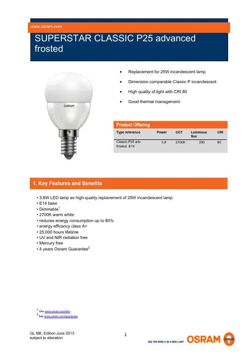
∙Replacement for 25W incandescent lamp∙Dimension comparable Classic P incandescent∙High quality of light with CRI 80∙Good thermal managementProduct OfferingType reference Power CCT LuminousfluxCRIClassic P25 advfrosted E143.8 2700K 250 801See /dim2See /guarantee1. Key Features and Benefits• 3.8W LED lamp as high-quality replacement of 25W incandescent lamp• E14 base• Dimmable1• 2700K warm white• reduces energy consumption up to 80%• energy efficancy class A+• 25,000 hours lifetime• UV and NIR radiation free• Mercury free• 4 years Osram Guarantee2Average Luminous lifetime 4 FluxSwitching cycles (30s on, 30s off) Casing materialStarting timeWarm up time for 60% lightPower factor25,000h 250lm100.000 Plastic <1snone 0.5Mercury max.Base Type Length Diameter Weight Tc temperature max.5Nominal current (steady state)Inrush current0.0mg E14 82mm 43mm 43g 85°C 33mA 4,2AGood heat exchange supports ideal performance 4 The average lifetime of LED lamps is defined as the number of hours when the light output of 50% of a large group of identical lamps goes below 70% of its initial luminous flux (L70B50, IEC60969).The lifetime is estimated at room temperature (25°C), free air burning, base up burning position and at rated voltage. To achieve a full lifetime a good heat exchange for the electronic components is required.5 The Tc is defined as the highest permissible temperature which may occur on the outer surface of the LED lamp (in the indicated position) under normal operating conditions and at the rated voltage/current/power or the maximum of the rated voltage/current/power range (DIN EN 62031: 2009-01) 4. Disposal information WEEE-lamps can be returned at specific collection points.LED lamps have to be disposed as special waste.Applications∙ hotels∙ restaurant∙ commercialareas∙ residentials∙art galleries and museum ∙ officespace Application Notes1. suitable for indoor application.2. for outdoor applications and operation in damplocations special approved fixture arerequired.3. Input voltage: 220-240V4. Operating temperature range between -20°Cand 40°C5. Storage temperature & humidity conditions-20°C up to +40°C95% relative humidity6. Working temperature & humidity conditions-20°C up to +40°C95% relative humidityType reference Product Number – 1pcs Product Number – 1 shipping unit Number of pcs / ship. unit CLASSIC P25 advfrosted E144052899911406 4052899911482 62004/108/EC Electromagnetic compatibility (EMC)2009/125/EC Ecodesign requirements for energy related products2011/65/EC Restriction of the use of certain hazardous substances in electrical and electronic equipment (RoHS)1907/2006 Registration, Evaluation, Authorisation and Restriction of Chemicals (REACH Regulation)2002/96/EC Waste Electrical and Electronic Equipment Directive (WEEE)EN 62471 Photobiological safety of lamps and lamp systemsIEC/TR 62471-2 Photobiological safety of lamps and lamp systems - Part 2: Guidance on manufacturing requirements relating tonon-laser optical radiation safetyEN 55015 Limits and methods of measurement of radio disturanceEN 61000-3-2 Electromagnetic compatibility – Limits for harmonic current emissionEN 61000-3-3 Electromagnetic compatibility – Limitation of voltage changes, voltage fluactuations, flicker in public low voltagesupply systemsEN61547Electromagnetic compatibility immunity requirementsBrandModelLeading orTrailingDimming range MaxMinHPM CAT250L HPM L 99.7% 49.5% Clipsal E30 (32V500M) L 98.3% 97.9% Bticino SM9350S L 100.3% 34.0% Panasonic WEG57513K L 100.3% 37.1% Honyar 鸿雁KT150 L 100.0% 38.7%Panasonic WMS549 L 104.1% 52.1% Siemens 5TGO200-1CC1 L 100.3% 27.8% CLIPSAL E84752D500 T 101.0% 7.0% Panasonic WEJ57515 L 103.6% 21.6% HPM CAT200L HPM L 103.6% 44.8%DETA 6021 L 102.4% 6.2%6 LegendL / leading edge T / trailing edge6Typical values. Test performed exemplary on PARATHOM CLASSIC P25 adv frostedThe test results reflect the measurement of the individual devices that were used in tests. OSRAM does not take over any responsibility, warranty or liability that this results can also be achieved by using the devices under other conditions or when using successor models of the tested devices or different models of the same manufacturer.The test results were achieved by using the above mentioned LED-lamp types. OSRAM does not take over any responsibility, warranty or liability that this results can also be achieved by using the devices under other conditions or when using other LED-lamp types.。
2025led灯珠规格书(原创实用版)目录1.2025LED 灯珠概述2.2025LED 灯珠规格参数3.2025LED 灯珠的特点与优势4.2025LED 灯珠的应用领域5.2025LED 灯珠的未来发展前景正文一、2025LED 灯珠概述2025LED 灯珠,顾名思义,是指尺寸为 2.0mm×2.5mm 的 LED 灯珠。
随着科技的发展,LED 灯珠在照明、显示等领域的应用越来越广泛,不同的尺寸和规格可以满足各种不同的应用需求。
2025LED 灯珠作为其中一种规格,具有其独特的优势和特点。
二、2025LED 灯珠规格参数2025LED 灯珠的主要规格参数如下:1.尺寸:2.0mm×2.5mm2.颜色:红、绿、蓝、黄、白等多种颜色可供选择3.亮度:根据不同颜色和芯片,亮度有所不同,一般可达到几百至几千 mcd(毫坎德拉)4.视角:根据不同型号和需求,视角可在 30°至 120°之间选择5.工作电压:通常为 1.8V 至 3.0V,也可根据客户需求定制6.工作温度:-40℃至 +85℃三、2025LED 灯珠的特点与优势2025LED 灯珠具有以下特点和优势:1.小巧轻便:尺寸小巧,重量轻,便于安装和携带2.节能环保:LED 灯珠具有节能、低耗、低热量的特点,符合绿色环保要求3.寿命长:LED 灯珠寿命可达到 5 万小时以上,远高于传统照明设备4.稳定性好:抗震动、抗冲击性能好,适应各种恶劣环境5.色彩丰富:可根据需要提供多种颜色,满足不同场合和需求四、2025LED 灯珠的应用领域2025LED 灯珠广泛应用于以下领域:1.指示灯:如电子设备、家电产品、交通工具等的状态指示灯2.显示屏:如 LED 显示屏、广告牌、交通信号灯等3.照明设备:如手电筒、台灯、灯带等4.其他:如玩具、礼品、装饰等五、2025LED 灯珠的未来发展前景随着 LED 技术的不断进步和市场需求的日益增长,2025LED 灯珠在未来的发展前景广阔。
hrs3301规格书【最新版】目录1.HRS3301 规格书概述2.HRS3301 规格书的主要内容3.HRS3301 规格书的特点和优势4.HRS3301 规格书的应用领域5.总结正文一、HRS3301 规格书概述HRS3301 规格书是一份详细的技术文档,它主要描述了一种名为HRS3301 的产品的各项性能、功能、设计参数和测试方法等。
这份规格书旨在为产品设计人员、工程师、测试人员和用户提供全面的技术参考,以便更好地理解和使用 HRS3301 产品。
二、HRS3301 规格书的主要内容HRS3301 规格书主要包括以下几个方面的内容:1.产品概述:介绍 HRS3301 产品的基本信息,如产品名称、型号、功能、应用领域等。
2.功能性能:详细描述 HRS3301 产品的各项功能和性能指标,如工作电压、工作电流、响应时间、传输速率等。
3.设计参数:提供 HRS3301 产品的各项设计参数,如尺寸、重量、材质等,以便产品设计人员进行相关设计。
4.测试方法:介绍 HRS3301 产品的各项测试方法和测试标准,以便测试人员进行产品测试。
5.使用说明:提供 HRS3301 产品的使用方法和注意事项,以便用户正确使用产品。
6.维护保养:介绍 HRS3301 产品的维护保养方法和技巧,以延长产品使用寿命。
三、HRS3301 规格书的特点和优势HRS3301 规格书具有以下几个特点和优势:1.详细的技术描述:规格书对产品的各项性能、功能和设计参数进行了详细的描述,使用户能够全面了解产品。
2.权威的测试方法:规格书提供了权威的测试方法和测试标准,确保产品测试的准确性和可靠性。
3.易懂的使用说明:规格书提供了易懂的使用说明,方便用户正确操作和使用产品。
4.实用的维护保养技巧:规格书介绍了实用的维护保养方法和技巧,有助于延长产品使用寿命。
四、HRS3301 规格书的应用领域HRS3301 规格书主要应用于以下几个领域:1.电子产品设计:为设计人员提供详细的产品性能和设计参数,以便进行相关设计。
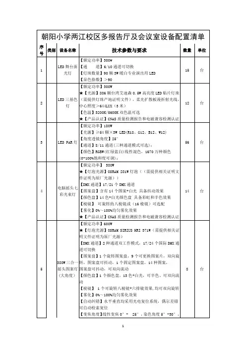
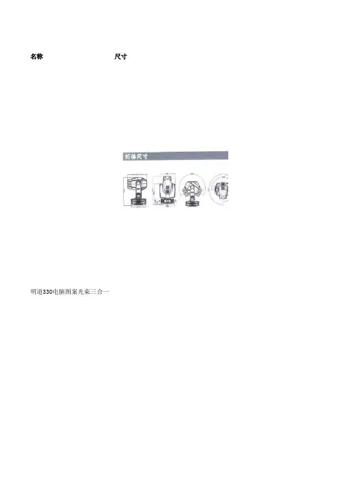
名称尺寸
明道330电脑图案光束三合一
技术参数
额定电压: AC100V-240V,50/60Hz
光源规格: OSRAM SIRIUS HRI 330W XL新型一体灯泡,平均寿命1500H
色 温: 7000K
出光角度:光束/图案4°~26°线性变焦;柔光18°~36°线性变焦
线性调光:机械线性调光0~100%
高速频闪:脉冲频闪,同步异步频闪. 频闪速度每秒1-20次
固定颜色:1个固定颜色轮有12个色片+白光,可半色效果、线性色彩转换及双向变速旋转彩虹效果
动态图案:1个旋转图案轮有8个可选图案片+白光,可变速抖动/双向流动效果,图案索引功能及16Bit精确微调
棱 镜: 1个独立的三面棱镜,双向变速旋转
调 焦: 采用高精密玻璃光学镜头,电子线性高清调节
雾 化: 独立的雾化效果,光斑柔和自然,光斑大小线性自由缩放
水平/垂直:水平扫描角度540°,垂直扫描角度270°,采用三相电机快速平滑扫描并消除传动噪音
显示界面:采用宽屏LCD液晶中英文显示界面。
LE B P1MS 数据表P r e l i m i n a r y d a t a s h e e t v e r s i o nLE B P1MS数据表初稿Published by ams-OSRAM AGTobelbader Strasse 30, 8141 Premstaetten, Austria Phone +43 3136 500-0P r e l i m i n a r y d a t a s h e e t v e r s i o nOSRAM OSTAR ® Projection PowerLE B P1MS欧司朗 OSTAR Projection Power 是一款用于投影应用的高亮度 LED。
应用-投影和显示特点-封装: 用于投影仪的高功率 OSTAR -芯片技术: UX:3-典型辐射值: 120° (朗伯发射极) -颜色: λdom = 456 nm (● blue)-ESD: 2 kV acc. to ANSI/ESDA/JEDEC JS-001 (HBM, Class 2)订购信息型号总辐射通量 1)订单码I F = 4000 mA ΦeLE B P1MS-EQET-237630 ... 10420 mWQ65113A4266P r e l i m i n a r y d a t a s h e e t v e r s i o n最大额定参数图形符号值储存温度T stg 最小值 最大值-40 °C 100 °C 结温T j 最大值150 °C 正向电流 T j = T j,maxI F 最小值 最大值200 mA 6700 mA 正向脉冲电流D = 0.7; f = 240 Hz; T j = T j,max I F pulse 8000 mA 浪涌电流t P ≤ 50 μs; D = 0.1 ; T j = T j,maxI FS 最大值9500 mAESD耐受电压acc. to ANSI/ESDA/JEDEC JS-001 (HBM, Class 2)V ESD 2 kV 反向电流 2)I R最大值200 mA 正极板与负极板最大电压差|∆V a-b |, |∆V c-b |最大值40 VP r e l i m i n a r y d a t a s h e e t v e r s i o n特性T Board = 25 °C; I F = 4000 mA; f = 1000 Hz; D = 0.25 参数图形符号 值峰值波长λpeak 典型值450 nm 主波长 3)λdom最小值 典型值 最大值452 nm 456 nm 460 nm 光谱带宽, 50% I rel,max ∆λ典型值23 nm 50% I V 处视角2φ典型值120 °辐射面A color 典型值 1.95 x 1.35mm²部分通量(根据CIE 127:2007) 4) I F = 4000 mA ΦE/V, 120°典型值0.77正向电压 5) I F = 4000 mAV F最小值 典型值 最大值 6.4 V 6.8 V 7.6 V 反向电压(静电放电器件)V R ESD 最小值45 V 反向电压 2) I R = 20 mAV R 最大值 1.2 V 实际热阻 PN结/焊点R thJS real 典型值 1.30 K / W 电热阻 PN结/焊点with efficiency ηe = 31 %R thJS elec.典型值1.0 K / WP r e l i m i n a r y d a t a s h e e t v e r s i o n亮度组组总辐射通量 1)总辐射通量 1)I F = 4000 mA I F = 4000 mA 最小值最大值ΦeΦeEQ 7630 mW 8200 mW ER 8200 mW 8920 mW ES 8920 mW 9700 mW ET9700 mW10420 mW波长组组主波长 3)主波长 3)最小值最大值λdomλdom2452 nm 456 nm 3456 nm460 nm标签信息示例: EQ-2亮度组波长EQ2P r e l i m i n a r y d a t a s h e e t v e r s i o n相对光谱发射4)E rel = f (λ); IF = 4000 mA; T J = 25 °C350400450500550600650700750800λ/nm0.00.20.40.60.81.0E rel辐射特性4)I rel = f (ϕ); T J = 25 °CLE B P1MS-100°-90°-80°-70°-60°-50°-40°-30°-20°-10°0°10°20°30°40°50°60°70°80°90°ϕ/°0.00.20.40.60.81.0I relP r e l i m i n a r y d a t a s h e e t v e r s i o n相对部分光通量4)ΦE (2φ)/ΦE (180°) = f(φ); T J = 25 °C0.00.20.40.60.81.0Φe (2ϕ)Φe (180°)P r e l i m i n a r y d a t a s h e e t v e r s i o n正向电流4)I F = f(V F ); T J = 25 °C20010002000300040005000600070008000I F /mA相对辐射功率4),6)ΦE /ΦE (4000 mA) = f(I F ); T J = 25 °C2002000400060008000I F /mA0.00.20.40.60.81.01.21.41.61.8Φe Φe (4000mA )主波长4)Δλdom = f(I F ); T J 2002000400060008000I F /mA-6-4-202468∆λdom /nmP r e l i m i n a r y d a t a s h e e t v e r s i o n正向电压4)ΔV F = V F - V F (25 °C) = f(T j ); I F = 4000 mA-0.6-0.4-0.20.00.20.4∆V F /V相对辐射功率4)ΦE /ΦE (25 °C) = f(T j ); I F = 4000 mA-40-20020406080100120140T j /°C0.00.20.40.60.81.01.2Φe Φe (25°C)主波长4)Δλdom = λdom - λ-40-20020406080100120140T j /°C-8-6-4-20246810∆λdom /nmP r e l i m i n a r y d a t a s h e e t v e r s i o n尺寸图7)备注:近似重量:380.0 mgESD建议:该产品由与芯片并联的ESD防护器件提供保护. 标注:封装不适合任何湿式清洗或超声波清洗P r e l i m i n a r y d a t a s h e e t v e r s i o n内部电子电路P r e l i m i n a r y d a t a s h e e t v e r s i o n推荐焊盘7)为了在回流焊和运输过程中保护LED, 产品表面粘贴了一层保护膜。
osram灯珠命名规则OSRAM是一家具有领先地位的全球性照明光源制造公司。
其灯珠产品在市场中占据着重要的地位。
OSRAM灯珠命名规则是指OSRAM 公司对其生产的灯珠进行命名的规则。
了解这些规则对于理解OSRAM产品的特性和功能非常重要。
OSRAM灯珠的命名规则最初由德国OSRAM公司制定,现在已经被全球的OSRAM分支机构采用。
OSRAM灯珠的命名规则基于以下几个需要考虑的因素:1. 功能特性: OSRAM灯珠的命名规则首先考虑的是灯珠的功能特性。
就像其他照明产品一样,灯珠的功能特性可以包括亮度、颜色、显色指数、色温等。
2. 电参数: OSRAM灯珠命名规则中也包括了灯珠的电参数。
这些参数包括电压、电流和功率等。
这些参数是灯珠运行的必要条件,保证了其正常工作,并且在照明装置中与其他部件协调。
3. 尺寸: 正如其他电子元器件一样,OSRAM灯珠的命名规则也考虑了其尺寸特性。
在设计照明装置时,灯珠的尺寸和形状必须与其他装置部件相吻合。
OSRAM灯珠的命名规则通常由四个字母和数字组成。
这些字母和数字代表了灯珠的不同特性。
第一个字母: 代表产品类型。
常见的类型包括:• O:Oslon高功率LED• D:Duron中功率LED• G:Golden Dragon高性价比LED• L:Linearc LED• S:Surface Mounted Device(SMD)LED第二个字母: 代表颜色温度。
常用的颜色温度包括:• N:中性色温• W:白色清凉色温• H:黄色温暖色温第三个字母: 代表灯珠的呈现方式。
通常是将这个字母与数字一起使用,数字表示灯珠的大小或功率。
• P:Point Source LED• M:Multichip LED• F:Flat LED第四个字母: 代表灯珠的电参数。
常用的电参数包括:• A:极大值电流• F:额定电通量• P:额定功率• V:DC倍压例如,从命名规则OSLON-SSL-120代表OSLON高功率LED,中性色温,Flat LED型号和最大电流为120mA。
System Specification ConfidentialSystem SpecificationSIRIUS HRI TM 330W XLPT SIRIUS 330W - UNISHAPE®Revision Chapter Changes DateInitial draft 01.11.2012 TaSystem Specification ConfidentialTable of Contents1. Product Scope (3)2. Product Specifications: Lamp SIRIUS HRI 330W XL (3)2.1 Dimensions and weight (3)2.2 Marking on lamp (3)2.3 Lamp drawing (4)2.4 Lamp cables and connector (4)2.5 Operating and measurement conditions (5)2.6 Light output (5)2.7 Operation modes (6)2.7.1Internal synchronization (free running mode) (6)2.7.2 External synchronization (preprogrammed UNISHAPE default waveform) (6)2.7.3External synchronization (customized UNISHAPE waveforms) (7)2.8 Temperature and lamp cooling (8)2.9 Typical lamp characteristics (initial) (10)2.10 Average lamp life and lumen maintenance (10)2.11 Light output measurement (11)2.12 Rise time (11)2.13 Hot restrike (11)2.14 Cold ignition (12)2.15 Outgoing inspection (12)2.16 Instructions for use (13)3. Product Specifications: Lamp driver PT SIRIUS 330W - UNISHAPE® (14)3.1. Dimensions and Weight (14)3.2 Basic Lamp Driver Data (14)3.3 Lamp Driver Geometry (16)3.4 Maximum Temperatures (17)3.5 Control Board Interface (19)3.5.1 Basic Data (19)3.5.2 UART Communication (20)3.5.3 Scale Factors (21)3.6 Control Board Signals (21)3.6.1 Lamp Driver Start & Shut-Down (Non-UART mode) (21)3.6.2 Lamp Operation / SCI Control Signals (22)3.6.2.1 Internal Synchronization (22)3.6.2.2 External Synchronization with preprogrammed waveform (22)3.6.2.3 External Synchronization with customized waveforms (23)3.7 Lamp Driver Cable and Connectors (23)3.8 Lamp Driver 2D Barcode Label (24)4. Environmental requirements for lamp driver in fixture system (25)4.1 Reliability tests (25)4.2 Insulation requirements (26)4.3 General warnings (26)5. Packaging (27)5.1 Lamp (27)5.2 Lamp Driver (28)6. Disclaimer (29)System Specification Confidential1. Product ScopeThe product is a lamp system consisting of a short arc burner within a reflector and an electronic lamp driver. Lamp has to be operated with Voltage control (VC) functionality.Type lamp SIRIUS HRI 330W XLIdentcode: A A42 713Type driver PT SIRIUS 330W – UnishapeIdentcode: A A41 618The lamp must be operated with the OSRAM lamp driver only.2. Product Specifications: Lamp SIRIUS HRI 330W XL2.1 Dimensions and weightLamp see lamp drawing (page 4)Reflector type elliptical, E21.8Cable and connector NoneLamp weight < 150 g2.2 Marking on lampPosition of marking on the reflector, see 2.3Manufacturer OSRAMType no. SIRIUS HRI 330W XLCountry of origin Made in “Country”Hg-marking and WEEE-sign Hg ,System Specification Confidential2.3 Lamp drawing36Note: Tolerances of reflector measures +/- 0.5 mm2.4 Lamp cables and connectorCables NoConnectors noOsram recommends restricting the cable length between lamp driver and lamp to 300mm (limit 400mm). For details please refer to application note “Length of HV cabling for FP engines”.System Specification Confidential2.5 Operating and measurement conditionsLamp driver type The lamp must be operated with the lamp driverOSRAM PT SIRIUS 330WRated lamp wattage 280 - 330WIf one step dimming from rated to dimming mode is applied,temporary light variations may occur.Burning position any2.6 Light outputTest conditions 330W operation > 5 min for lamp output stabilizationLamp driver OSRAM PT SIRIUS 330W; Gen5; VCLuminous flux1I) Initial values :typ.: 15000 lm @ 5.0 x 3.8 mm2 rect. aperturemin.: 13800 lm @ 5.0 x 3.8 mm2 rect. Aperturetyp.: 16500 lm @ 6 mm2 round aperturemin.: 15000 lm @ 6 mm2 round apertureII) 24h values:min.: 90% of initial values measured @5.0 x 3.8 mm2 rect. apertureLumen measurement as described in 2.11 Spot position (Init. value) Max spot brightness (hot spot) is ≤ 0.8 mm offaperture centre, measured in OSRAM camera set up Color coordinates2typ.x: 0.300 +/- 0.020.typ.y: 0.300 +/- 0.020.1 Average of first sample production; Values preliminary, have to be verified by mass production2 Based on reference test assembly at OSRAMSystem SpecificationConfidential2.7 Operation modesThe SIRIUS HRI 330W XL lamp can be operated with multiple operation modes, depending on the specific application for which the lamp is used.In conjunction with the appropriate ballast PT SIRIUS 330W, following synchronization modes are possible:2.7.1 Internal synchronization (free running mode)The free-running mode is achieved by applying a continuous SCI signal. The lamp is operated with a fixed pulse timing and fixed lamp frequency. These parameters are pre-programmed in the ballast (see 3.6.2.1 for the details). As the external SCI signal is continuous, lamp currentcommutations occur in a non-synchronized way. Therefore, this mode can be used in those cases for which synchronization is not needed (LCD applications, light output measurements..)Lamp frequency Pulse duty cycle Pulse length Pulse height over plateau60 Hz10.0 %835 µs30%2.7.2 External synchronization (preprogrammed UNISHAPE default waveform)3This mode is achieved by applying a square wave SCI input. The pulse timing such as pulse-plateau-ratio and pulse duty cycle are fixed and pre-programmed in the ballast (see 3.6.2.2 for the details). The waveform is synchronized by an external SCI signal with a recommended duty cycle of 50%. Therefore, this mode can be used in those cases for which synchronization is needed, but for which additional features such as plateau-variation or low-pulses are not desired.The approved lamp frequency range is specified below. All not yet approved operation modes have to be released by OSRAM.Lamp frequency Pulse duty cycle Pulse length Pulse height over plateau50-60 Hz10.0 %835 µs - 1000 µs30%3For 3-Chip-Systems 12% pulse duty cycle and 55% pulse height over plateau is recommended, frequency range 47-78Hz is allowed.lampSCISystem SpecificationConfidential2.7.3 External synchronization (customized UNISHAPE waveforms)Only if a customized UNISHAPE waveform is applied, this mode will be used.Basic rules for UNISHAPE current waveforms and allowed parameter ranges are specified in the application note "UNISHAPE operating Modes for Front Projection".All Unishape modes should be approved by Osram before application. In all cases, the lamp must be operated without any DC content on the lamp current.Lamp frequency:It is recommended to commutate three times per frame so that the lamp frequency range is 72Hz to 95Hz, otherwise flickering could appear in case of 48Hz frame frequency and/or ECO-mode.Pulse height:For setting the pulse height of the UNISHAPE waveform, please refer to the application note "UNISHAPE – Universal Shaped Light Waveform” available @ /unishape /. Due to ballast current limitation, a constant ratio of pulse current to average current can only be achieved if the maximum segment height does not exceed 31% of the average value. For higher segment heights the pulse current to average current ratio might temporarily decrease down to 31% at the beginning of lamp life. For higher pulse heights, the impact on color deviation should be tested.lampSCILamp currentSystem SpecificationConfidential2.8 Temperature and lamp coolingThe lamp has to be operated with forced air cooling in order to ensure that lamp temperatures are withinspecification. The cooling design is crucial for achieving the specified maintenance and lifetime of the lamp in all allowed operating conditions. Care should be taken, that the bulb temperature stays within the specified limits in all arbitrary operation positions by a suitable cooling system design. OSRAM alsostrongly recommends avoiding a gradient from lower to upper overall temperature limits on a length smaller than 25 % of bulb perimeter.For temperature condition qualifying, OSRAM provides special TC/IR lamps of the specific lamp type for thermal measurement. The TC/IR lamp is a lamp with combination of IR detection holes on reflector and TC elements attached to specific locations.SPECIAL REMARK : For arbitrary lamp orientations, the position of hottest spot (defines as “hot spot”) and coldest spot (defines as “cold spot”) on the outer bulb surface is a dynamic one. Please see below picture for reference. The position of hot spot and cold spot sits in the area where the “temperature limits for overall bulb surface” (see next page) are specified, also the hot spot and cold spot must stay within the temperature requirements specified therein.When there is no forced cooling, due to the effect of gravity, bulb hot spot will always relate to the upmost part (or TOP) of the discharge vessel, and cold spot will always relate to the lowest part (or BOTTOM) of the bulb surface (case (a)).As the lamp axis tilting out of the horizontal plane, the hot and cold spot (red and blue mark) will move accordingly on the bulb surface as shown in (b).Once an angle of about 45 ° is exceeded, these spots are defined as in (c) and fixed for higher angles. For case (c) the “spot” concept of hot spot and cold spot could be no longer valid, which will become “belt” like zones at top side and bottom side.When a forced cooling is used, the hot spot and cold spot position could vary from the top and bottompositions. In such case, temperatures measured at top centre and bottom centre will not be the hottest and coldest anymore. If necessary, an IR camera is recommended to investigate the temperature distributions and cooling design.Other general remarks about temperature measurement:• Bulb temperatures are measured by IR-detection through holes drilled in the reflector.• For reliable results it is absolutely crucial that the bulb is free of any contamination inside andoutside, i.e. the bulb must be free of any blackening and devitrification.• Bulb temperatures must remain within the specified overall temperature limits everywhere on thebulb surface (orange marked area in picture), i.e. not only at top and bottom, but also in the sides. • Temperature recommendations are given for the bulb center position at top and bottom. For thedefinition of “top” and “bottom” under arbitrary lamp orientations see above.System Specification Confidential• When a pyrometer is used, the measurement spots “top” and “bottom” should coincide with the hotand cold spot defined above when the lamp is operated horizontally. Increasing the lamp tilt angle in principle corresponds to a line scan measurement as described in the application note “Measuring Lamp Temperatures”. An IR camera could generate more direct result with temperature distributions.• The pyrometer axis should be kept strictly perpendicular to the lamp axis (See below picture).Otherwise there is a risk of vignetting and out of measurement target.• Temperature measurement needs to be an average over at least three different lamps in the same fixture unit. This average temperature should meet the recommended temperatures. In addition, each individual lamp must meet the overall temperature limits – for each individual fixture unit. • After lamp shut down, cooling fan speed must not be increased for > 15 seconds to avoid extreme temperature gradients and the risk of cold cracks.Note: Example TC/IR lamp picture, practical appearance may vary.Operating power Recommended temperature at top/bottom center Temperature limits for overall bulb surface 4Foil / lead wire temperatures Top center : 860°C ± 20°C 330WBottom center : > 760°C740°C < T < 910°CTop center : 870°C ± 20°C 280WBottom center : > 770°C750°C < T < 920°CLead wire: T < 350°C Front foil: T < 350°C Back foil: T < 350°CFor further information, please refer to our application note “Measuring Lamp Temperature, Rev. 02”.4Real temperature requirement of the lamp burner. Hot spot and cold spot should stay within thetemperature specification, but since they cannot be easily found, thus the “Recommended temperature at top/bottom center” is specified as a more standard methodology.The “Temperature limits for overall bulb surface” applies to the full circumference extending over the length of inner bulb volume.System Specification Confidential2.9 Typical lamp characteristics (initial)Lamp power : 330 WMeasurement : Integrated sphereAperture: 5.0 x 3.8 mmRadiated PowerUV-output UVA 315-380 nm 6.0W typicalUVB 280-315 nm 0.04W typicalUVC 248-280 nm 0.02W typical Total visible flux 380-780 nm 74W typical IR 780-1020 nm 4 W typical2.10 Average lamp life and lumen maintenanceSwitching cycle 2 hrs on, 15 min offLamp life time5: 1500 hrs typical @ 330W2000 hrs typical @ 280WMore than 50% of lamp population have light output >50% of initial min. lumen output at the lamp life time. Lumen measurement as described in 2.11 with 6.0 mm ∅ round aperture.5 Life time proved in lab condition inside moving fixture at nominal power level.System Specification Confidential2.11 Light output measurementDrawing of measuring systemLight output measured at 31 mm distance into an integrating sphere with aperture.During assembly, the burner is positioned in the reflector in x, y and z coordinates for an optimized lumen output in accordance with the specified requirements.2.12 Rise timeRise time to 80% of the stabilized luminous output is < 90 sec without forced cooling. Extensivecooling of the bulb during lamp run-up phase has to be avoided. Osram suggests a delayed start of lamp cooling 20s after ignition. At all times temperatures at lead wire and front foil must staywithin specification as described in 2.8. Over time (within the first 30-60seconds) the lamp voltage is rising significantly and coming close to the final operation voltage and in the same way the power is rising until the nominal power is reached.2.13 Hot restrikeThe hot restrike time depends strongly on the cooling conditions after shut off. Under typicalcooling conditions it may vary from 60s to 120s. Extensive cooling within the first 15s after shut offhas to be avoided. Ignition voltage 2.6 kV typ. (3.5 kV max.)System Specification Confidential2.14 Cold ignitionCooling of the lamp during the ignition phase should be avoided, because this could lead to ignition failures.After a successful starting attempt keeps the lamp burning for at least 15 min.OSRAM advises to build in a multiple attempt cycle (3-5 successive attempts) to start the lamp.Between two successive attempts within the cycle there has to be at least a 15s pause.If a multiple attempts cycle does not lead to a lit lamp, this lamp can be claimed as “ignition failure”lamp.2.15 Outgoing inspectionAppearance check All lampsMarking check All lampsLamp voltage check All lampsIgnition check All lampsDimensions 5 pcs / 1000 lampsIntegral lumen All lampsSystem Specification Confidential2.16 Instructions for use- For lamp replacement: switch off power, disconnect mains supply, disconnect power cord, allow lamp to reach room temperature.- This SIRIUS HRI® lamp operates at high pressure and at high temperature and may unexpectedly shatter.- This SIRIUS HRI® lamp generates ultraviolet radiation which may cause skin and eye irritation with prolonged exposure.- This SIRIUS HRI® lamp must be operated only in suitably designed, enclosed fixtures which prevent direct observation of the arc and will prevent lamp fragments from exiting, in theunlikely event of a lamp rupture.- Do not touch the lamp with bare hands.- If necessary, lamp can be cleaned with lint free towel before operation.- Protect lamp environment against high ignition pulses (max. 3.5kV).- Avoid direct contact of objects to reflector or burner.- This lamp must not be operated with a broken, cracked or loose reflector.- Fast on-off-cycles (e.g. 10 min. on / 10 min. off) will reduce lamp life.- Visible arc instability has to be suppressed by optical system.- Operate lamp only in accordance with UL 1950 regulations.- Avoid back-reflection of light into burner.Disposal: For disposal of spent lamps, always consult federal, state, local andprovincial hazardous waste disposal rules and regulations to ensure properdisposal.Caution: This lamp emits ultra violet (UV) radiation and operates at high pressure.This lamp may only be used in enclosed fixtures that comply with UL1573.Due to the high luminous efficacy, the UV radiation which the lamp emitsand the high pressure within the lamp, SIRIUS HRI® lamps may only beoperated within enclosed, purpose-built housings.System Specification ConfidentialLF 5.5 330W 1.0mm x % pulse, UNISHAPE, Gen5 EDOS 581451 EAN3. Product Specifications: Lamp driver PT SIRIUS 330W - UNISHAPE®all values for lamp 330W 1.0mm3.1. Dimensions and WeightLamp driver 150x60x30 mmLamp driver weight 220 g3.2 Basic Lamp Driver Datanominal toleranceInput Voltage 380V DC 250...400V DCDC120V standby(non-operating) min.In stand by mode an overshoot of max. 420V and max. 500ms is acceptedmax.30V/us(du/dt)onSlew rate of input voltage at switchInput Current 1.0 AMax. input voltage ripple 30Vpp @ 100/120HzMax. input current ripple 1Arms @ 40-300kHzInput Wattage max. 365 W @330W lamp wattageInput Wattage standby operation 1,7W typical 2,5 W max.Output wattagenominal 330W ± 3% at RGBW sync 6DIM mode 280W ± 3% at RGBW sync 6controlled by UART 280W…330W in step width 1/128 of nominal power Output current limitation 6.5A (RMS) ± 5%Ignition pulse typ. 2.6 kVpeak symm. 2.1 .. 3.5 kVpeakIgnition Phase Duration typ. 3.5s max. 6 sEnable-Disable-Enable Cycle 15 s min.Acoustic sound pressure level typical acoustic sound pressure level 36 dB(A), maximum 40dB(A) at 25cm measuring distance; measured in steady statelamp operation 7Acoustic sound power level typical acoustic sound power level 32 dB(A), maximum 36dB(A) acc. to EN ISO 3744; measured in steady state lampoperation 7Switch-off lamp voltage 145 V ± 5VCooling method forced air cooling at ≥1.5 m/s minimumThermal Protection Tc1 switch point 95° ± 5°CSafety Protections The lamp connections are not mains isolated. The lamp canbe switched on via the Start Control Input signal (SCI). TheStart Control Input and the Flag Output are mains isolated.6 Measured at real lamp load. Deviations will occur on all kind of artificial loads (e.g. resistor)7 Measured with RGB waveform. Customer generated UNISHAPE waveforms can lead to noise deviation.System Specification Confidential Output Protection short circuit + output / - output for max. 10sno protection for output short or arc to GNDStandardsSafety Standards IEC60950-1, UL60950-1EMI Standards the lamp driver is designed to meet the EMI standardFCC47 part 15 class B (radiated & conducted)EN55022 / CISPR 22 (radiated & conducted) in theapplicationNote: According to the 'Engineering Conditions of Acceptability' of the UL report and CB report the lamp driver has to be secured by a delayed 5A fuse in the supply circuit (PFC).Output Power Curve (Internal mode)Note: This output power curve is an example of one sample and is valid with tolerances from chapter 3.2 only for preprogrammed waveform with original parameter settings.System SpecificationConfidential3.3 Lamp Driver GeometryNominal Tolerance geometry: length 150.0 mm ± 0.5 mm width 60.0 mm ± 0.5 mm height 30.0 mm ± 1.0 mm mounting holes diameter4.2 mm ± 0.1 mm distance between hole centers long side 140.0 mm± 0.2 mm short side 50.0 mm ± 0.2 mmTc1 switch point (temperature sensor NTC at bottom side of PCB): 95°C ± 5°CExample picturePosition print top:CJ2air flow direction41212System Specification ConfidentialPosition print bottom side of PCB. R4 (NTC) temperature sensor, Tc1 switch point: 95°C ± 5°Cpower supply pin 1 GNDconnector CJ1 pin 2 + 380V DClamp output pin 1 lamp outputconnector CJ4 pin 2 lamp output3.4 Maximum TemperaturesComponent temperatures have to stay below the following limits in all operation modes: 100°CT2..T5T1, T8 95°CD1 90°CL3100°CL2,L4 85°CC1,C5 80°CNote: Overheating of T2-T5 and L3 components is possible if more than 5 not successful ignition attempts are made consecutively without sufficient pause. Pause length depends on intensity of cooling. Please check in such case the component temperatures stays below max. allowed values under worst case conditions.System Specification ConfidentialA thermo sense NTC is located on bottom of the PCB. Its temperature can be read out via UART, see application note “Standardized UART Protocol”. The relation between temperature and UART value follows below characteristics:The ballast is switched off for thermal protection if the NTC temperature exceeds 95°C ± 5°C The ballast is switched off if the read-out value exceeds 35968For a proper thermal design the read-out value should be above 44000 (< 80°C)The calculation from the read out UART value to the related value in degree Celsius can be done by calculating the 3 following equations consequently, where:t UART is the readout value with dimension 1, U NTC is the calculated voltage from the first equation, R NTC is the calculated resistor value from the second equation and the t NTC is the resulted temperature in °C. (LN means natural logarithm.)[]V V T U UART NTC 1625⋅=[]Ω−Ω⋅=NTCNTC NTCU V U R 54700[]Celsius R LN T NTC NTC °−+⎟⎟⎠⎞⎜⎜⎝⎛⎟⎠⎞⎜⎝⎛=15,27315,298145001015REMARK: NTC temperature can not precisely represent the temperatures of the components. Hence the fixture maker has to ensure that temperatures of the components stay below the limits under worst case conditions.System SpecificationConfidential3.5 Control Board Interface 3.5.1 Basic Datacontrol board PIN 1 Flag / TxD+ (collector) connector CJ2 PIN 2 Flag / TxD- (emitter)PIN 3 Common LED+ (anodes) PIN 4 SCI / Sync. (cathode LED) PIN 5 DIM / RxD (cathode LED)LED interface current level requirements• LED OFF current (Pin 4 or 5) 0 ... 0.1 mA • LED ON current (Pin 4 or 5) 4…6 …20 mADimensioning of LED series resistors:Recommended Values of R1, R2 for best operation conditionsFlag output (open collector) in non-UART mode PIN 1 → PIN 2 closed if lamp is on max. 3mA PIN 1 → PIN 2 open if lamp is offNote: signal must stay stable for min. 0.5s for right indicationSCI input (Lamp driver enable and/or synchronization input)• if T1 is switched ON the Lamp driver starts the lamp (Æ SCI ON)• square wave input allowed: refer to 3.6.2.2.External Synchronization Mode• for basic external synchronization timing requirements please refer to chapter 2.8 • ignition will be initiated within 100ms after valid SCI signal is detected,then Lamp driver will try to start lamp for max. 6s• Correct judgment of the Flag output (Lamp_Lit signal) is possible earliest 6s after a valid SCI signalis applied.• valid SCI signal is ignored for 15s after shutdownU +LED R1 R2 3,3V 100R 100R 5V 390R 390R 10V 1k2 1k2 15V 2k2 2k2 Pin 5Pin 1System Specification ConfidentialDIM/RxD inputNon UART mode only:• if T2 is switched OFF (or not connected) the Lamp driver is operating in full power mode • if T2 is switched ON the Lamp driver is operating in DIM mode (reduced lamp power)3.5.2 UART CommunicationActive solution for the interface on projector side in case of UART-communication is mandatory . Passive solution for the UART-interface on the projector side doesn’t work..• For additional information on the interface hardware, please refer to application note“5pin_interface” (How to connect the Control Board Interface).• For additional information on UART operation mode, please refer to application note“Standardized_UART_Protocol”.• The application notes are available on /Unishape/Note:If the active solution is used for the projector interface there is no current limitation necessary for the TxD photo coupler transistor.The photo coupler transistor will limit the current to <10mA .A current limitation for the TxD photo coupler transistor on the projector side will affect the signal quality adversely.UART Communication - Passive solutionPassive solution for the interface on the projector side is not permissible with this lampdriverR1R2System Specification Confidential3.5.3 Scale FactorsScale Factors for Read-out of Operation ParametersBallast operation parameters can be read out via UART (see application note “Standardized UART Protocol”, section 2.2.2). To convert the Microcontroller values into physical units, the following scale factors apply :Parameter Scale factor Ballast specific valueLamp voltagef_U (170 V / 65535)Lamp current f_I(6.2 A / 1023) Lamp power f_P(1 W)3.6 Control Board Signals3.6.1 Lamp Driver Start & Shut-Down (Non-UART mode)Error! Reference source not found. shows the main states of the lamp driver. Under normal conditions, the driver ignites the lamp after a valid SCI signal has been applied. After successful ignition the lamp driver turns to steady state lamp operation. If the SCI signal is switched off or if an error occurs, the lamp driver stops lamp operation.The flag output ( PIN 1 → PIN 2) is closed during the lamp driver states marked green and open during the lamp driver states marked red (see Figure 1). Ignitionlamp lit?Figure 1: Lamp Driver State DiagramSystem Specification Confidential3.6.2 Lamp Operation / SCI Control SignalsThe system can be operated with external synchronization (UNISHAPE®).The synchronization timing is selected by applying the corresponding valid SCI input signal.In addition to this, the lamp can be operated on internal synchronization if no external signals are available. These synchronization modes are possible:a) internal synchronization (free running mode) see 3.6.2.1 Internal Synchronizationb) external synchronization (UNISHAPE®) with the preprogrammed waveform see 3.6.2.2 External Synchronizationc) external synchronization (UNISHAPE®) with the customized waveform see 2.7 Operation modesFor details see the ”Application note Gen5 series UNISHAPE® firmware“.3.6.2.1 Internal Synchronization- apply continuous SCI input current (via T1 ON to SCI)- passive control by free running mode e.g. for LCD application3.6.2.2 External Synchronization with preprogrammed waveform- apply square wave SCI input current (via T1 ON to SCI)- the waveform is synchronized with SCI signal- recommended SCI-on duty cycle is 50%- pulse - plateau - ratio – is max. 130 % see diagram belowExample curve of one sample. Please consider tolerances mentioned in chapter 3.2.。