降压芯片MP1591_PDF
- 格式:pdf
- 大小:225.87 KB
- 文档页数:10

600KHz 36V/1.2A Synchronous Step-down ConverterGeneral DescriptionThe LP6498A is a synchronous step-down regulatorfromahighvoltageinputsupply.Operating with an input voltage range from 4.5V to 30V.1.2A continuous output current .The converter integrates a main switch and a synchronous rectifier for high efficiency without an external Schottky diode. LP6498A Requires a minimum number of readily available standard external components.over current protection and thermal shutdown . output short circuit protection. The LP6498A converters are available in the industry standard SOT23-6 packages.Order InformationLP6498A□ □ □F: Pb-FreePackage TypeB6:SOT23-6Applications✧ Car Charger / Adaptor✧ Pre-Regulator for Linear Regulators ✧ Distributed Power Systems✧ USB Dedicated Charging Ports (DCP)Features◆ Input Voltage Range: 4.5V to 30V ◆ Output Voltage Range: 0.8V to 12V◆ 1200mA Load Current ◆ Up to 93% Efficiency◆ 600KHz Switching Frequency◆ Short Circuit Protection ◆ Thermal Fault Protection ◆ S O T 23-6 Package◆ RoHS Compliant and 100% Lead (Pb)-FreeTypical Application CircuitMarking InformationVINFunctional Pin DescriptionPin DescriptionNC No connection.GND Ground.FB Feedback Input.Vout=(R1R2+1)×V FBFunction DiagramAbsolute Maximum Ratings✧VIN\SW \EN to GND ---------------------------------------------------------------------------------------------- -0.3V to 36V ✧VOUT\LED\RV\FB to GND --------------------------------------------------------------------------------------- -0.3V to 6.5V ✧Maximum Junction Temperature -------------------------------------------------------------------------------------- 150°C ✧Storage Temperature ------------------------------------------------------------------------------------------ -65℃ to 165℃✧Operating Ambient Temperature Range (TA) ------------------------------------------------------------- -20℃ to 85°C ✧Maximum Soldering Temperature (at leads, 10 sec) ------------------------------------------------------------- 260°CNote 1. Stresses beyond those listed under “Absolute Maximum Ratings” may cause permanent damage to the device. These are stress ratings only, and functional operation of the device at these or any other conditions beyond those indicated in the operational sections of the specifications is not implied.Exposure to absolute maximum rating conditions for extended periods may affect device reliability.Thermal Information✧Maximum Power Dissipation (SOT23-6, P D, T A=25℃) ------------------------------------------------------------ 0.6W ✧Thermal Resistance (SOT23-6, θJA) ------------------------------------------------------------------------------ 200℃/W ESD Susceptibility✧HBM(Human Body Mode) -------------------------------------------------------------------------------------------------- 2KV ✧MM(Machine Mode) --------------------------------------------------------------------------------------------------------- 200VElectrical CharacteristicsV IN=12V, V EN=5V, T A=25℃, unless otherwise notedHiccup Time 6Soft-start Time0.8Oscillator Frequency 600Typical Operating CharacteristicsOperation InformationFunctional DescriptionThe LP6498A is a switch-mode step-down DC-DC converter. The device operates at a fixed 600KHz switching frequency, and uses a slope compensated current mode architecture. This step-down DC-DC converter can supply up to 1.2A output current at input voltage range from 4.5V to 30V. It minimizes external component size and optimizes efficiency at the heavy load range. The integrated slope compensation allows the device to remain stable over a wider range of inductor values so that smaller values (6.8μH to 22μH) with lower DCR can be used to achieve higher efficiency. Layout GuidanceWhen laying out the PCB board, the following layout guideline should be followed to ensure proper operation of the LP6498A:1. The power traces, including the GND trace, the SW trace and the IN trace should be kept short, direct and wide to allow large current flow. The L connection to the SW pins should be as short as possible. Use several VIN pads when routing between layers.2. The input capacitor (C IN) should connect as closely as possible to VIN and GND to get good power filtering.Packaging InformationSOT23-6。

NCP1595, NCP1595A Current Mode PWM Converter for Low Voltage OutputsThe NCP1595/NCP1595A is a current mode PWM buck converter with integrated power switch and synchronous rectifier. It can provide up to 1.5 A output current with high conversion efficiency. High frequency PWM control scheme can provide a low output ripple noise. Thus, it allows the usage of small size passive components to reduce the board space. In a low load condition, the controller will automatically change to PFM mode for provides a higher efficiency at low load. Additionally, the device includes soft−start, thermal shutdown with hysteresis, cycle−by−cycle current limit, and short circuit protection. This device is available in compact 3x3 DFN package.Features•High Efficiency 95% @ 3.375 V•Synchronous Rectification for Higher Efficiency in PWM Mode •Integrated MOSFET•Fully Internal Compensation•High Switching Frequency, 1.0 MHz•Low Output Ripple•Cycle−by−cycle Current Limit•Current Mode Control•Short Circuit Protection•Built−in Slope Compensation for Current Mode PWM Converter •$1.5% Reference V oltage•Thermal Shutdown with Hysteresis•Ext. Adjustable Output V oltage•Fast Transient Response•Low Profile and Minimum External Components •Designed for Use with Ceramic Capacitor•Compact 3x3 DFN Package•These are Pb−Free DevicesTypical Applications•Hard Disk Drives•USB Power Device•Wireless and DSL ModemsSee detailed ordering and shipping information in the package dimensions section on page 11 of this data sheet.ORDERING INFORMATIONINV INFigure 1. Typical Operating CircuitABSOLUTE MAXIMUM RATINGSRating Symbol Value Unit Power Supply (Pin 4, 5)V IN7.0−0.3 (DC)−1.0 (100 ns)VInput / Output PinsPin 1,3,6V IO 6.5,−0.3 (DC)−1.0 (100 ns)VThermal Characteristics3x3 DFN Plastic PackageMaximum Power Dissipation @ T A = 25°CThermal Resistance Junction−to−AirP DR q JA145068.5mW°C/W Operating Junction Temperature Range (Note 4)T J−40 to + 150°C Operating Ambient Temperature Range T A−40 to + 85°C Storage Temperature Range T stg− 55 to +150°C Moisture Sensitivity Level (Note 3)1−Stresses exceeding Maximum Ratings may damage the device. Maximum Ratings are stress ratings only. Functional operation above the Recommended Operating Conditions is not implied. Extended exposure to stresses above the Recommended Operating Conditions may affect device reliability.NOTE:ESD data available upon request.1.This device series contains ESD protection and exceeds the following tests:Human Body Model (HBM) 2.0 kV per JEDEC standard: JESD22−A114.Machine Model (MM) 200 V per JEDEC standard: JESD22−A115.tchup Current Maximum Rating: 150 mA per JEDEC standard: JESD78.3.Moisture Sensitivity Level (MSL): 1 per IPC/JEDEC standard: J−STD−020A.4.The maximum package power dissipation limit must not be exceeded.PD+TJ(max)*T AR q JAELECTRICAL CHARACTERISTICS(V IN = 5.0 V, V OUT = 1.2 V, T A = 25°C for typical value, −40°C v T A v 85°C for min/max values unless otherwise noted)Characteristic Symbol Min Typ Max Unit Operating Voltage V IN 4.0− 5.5V Under Voltage Lockout Threshold V UVLO 3.2 3.5 3.8V Under Voltage Lockout hysteresis V UVLO_HYS180mVP FET Leakage Current (Pin 5, 4) T A = 25°CT A = −40°C to 85°C I LEAK−P1.01015m AN FET Leakage Current (Pin 3, 2) T A = 25°CT A = −40°C to 85°C I LEAK−N1.01015m AFEEDBACK VOLTAGEFB Input Threshold (T A = −40°C to 85°C)V FB0.7880.8000.812V FB Input Current I FB10100nA Overvoltage Protect Higher than FB Threshold (T A = 25°C)V OVP 2.0 5.010.0% THERMAL SHUTDOWNThermal Shutdown Threshold (Note 5)T SHDN TBD160−°C Hysteresis T SDHYS30°C PWM SMPS MODEMinimum ON−Time TON MIN100ns Switching Frequency (T A = −40°C to 85°C)F OSC0.8 1.0 1.2MHz Internal PFET ON−Resistance (I LX = 100 mA, V IN = 5.0 V, T A = 25°C)(Note 5)R DS(ON)_P−0.20.3WInternal NFET ON−Resistance (I LX = 100 mA, V IN = 5.0 V, T A = 25°C)(Note 5)R DS(ON)_N−0.150.22W Maximum Duty Cycle D MAX−−100% Soft−Start Time (V IN = 5.0 V, V o = 1.2 V, I LOAD = 0 mA, T A = 25°C) (Note 6)T SS− 1.0−ms Main PFET Switch Current Limit (Note 5)I LIM 2.0 2.5A ENABLE (NCP1595A)Enable Threshold High (NCP1595A Only)V EN_H 1.8V Enable Threshold Low V EN_L0.4V Enable bias current ( EN = 0 V)I EN500TBD nA Total DeviceQuiescent Current Into V CCP (V IN = 5 V, V FB = 1.0 V, T A = 25°C)I CCP10m A Quiescent Current Into V CC (V IN = 5 V, V FB = 1.0 V, T A = 25°C)I CC900m A Shutdown Quiescent Current into V CC and V CCP (NCP1595A Only)(EN = 0, V IN = 5 V, V FB = 1.0 V, T A = 25°C)I CC_SD 1.5 3.0m A5.Values are design guarantee.6.Design guarantee, value depends on voltage at V OUT.PIN FUNCTION DESCRIPTIONSPin #Symbol Pin DescriptionNCP15951FB Feedback pin. Part is internally compensated. Only necessary to place a voltage divider or connect the out-put directly to this pin.2GND Ground3LX Pin connected internally to power switch. Connect externally to inductor.4VCCP Power connection to the power switch.5VCC IC power connection.6NC No ConnectionNCP1595A1FB Feedback pin. Part is internally compensated. Only necessary to place a voltage divider or connect the out-put directly to this pin.2GND Ground3LX Pin connected internally to power switch. Connect externally to inductor.4VCCP Power connection to the power switch.5VCC IC power connection.6EN Device Enable pin. This pin has an internal current source pull up. No connect is enable the device. With this pin pulled down below 0.4 V, the device is disabled and enters the shutdown mode.V INV INFigure 2. Detail Block DiagramEXTERNAL COMPONENT REFERENCE DATADevice V OUT Inductor Model Inductor (L1)C IN (C1)C OUT (C2)R1R2NCP1595/ NCP1595A 3.3 V CDC5D23 3R3 (1 A)CDRH6D38 3R3 (1.5 A)3.3 m H22 m F22 m F x 222 m F22 m F x 231 k10 kNCP1595/ NCP1595A 2.5 V CDC5D23 3R3 (1 A)CDRH6D38 3R3 (1.5 A)3.3 m H22 m F22 m F x 222 m F22 m F x 221 k10 kNCP1595/ NCP1595A 1.5 V CDC5D23 3R3 (1 A)CDRH6D38 3R3 (1.5 A)3.3 m H22 m F22 m F x 222 m F22 m F x 28 k10 kNCP1595/ NCP1595A 1.2 V CDC5D23 3R3 (1 A)CDRH6D38 3R3 (1.5 A)3.3 m H22 m F22 m F x 222 m F22 m F x 25 k10 kTYPICAL OPERATING CHARACTERISTICSLOW SIDE AMBIENT TEMPERATURE, (T A /°C)0.000.050.100.150.200.250.30−4002585Figure 3. Switch ON Resistance vs.TemperatureL O W S I D E S W I T C H O N R E S I S T A N C E /WFigure 4. Feedback Input Threshold vs.Temperature0.7850.7900.7950.8000.8050.8100.815−4002585AMBIENT TEMPERATURE, (T A /°C)F B I N P U T T H R E S H O L D V F B /VFigure 5. Switching Frequency vs.Temperature0.70.80.91.01.11.21.3−4002585AMBIENT TEMPERATURE, (T A /°C)S W I T C H F R E Q U E N C Y , F O S C /M H ZFigure 6. Main P−FET Current Limit vs.Temperature1.51.82.02.32.52.83.0−4002585AMBIENT TEMPERATURE, (T A /°C)M A I N P −F E T C U R R E N T L I M I T , I L I M /V600700800900100011001200−402585AMBIENT TEMPERATURE, (T A /°C)Q U I E S C E N T C U R R E N T I N T O V C C , I C C /m A Figure 7. Quiescent Current Into V CC vs.Temperature0123456−4002585S H U T D O W N Q U I E S C E N T C U R R E N T , I C C _S D /m AAMBIENT TEMPERATURE, (T A /°C)Figure 8. Shutdown Quiescent Current vs.TemperatureFigure 9. Output Voltage Change vs. OutputCurrentFigure 10. Efficiency vs. Output CurrentFigure 11. Output Voltage Change vs.Output CurrentFigure 12. Efficiency vs. Output CurrentFigure 13. Efficiency vs. Output CurrentFigure 14. Output Voltage Change vs.Output Current−1.5−1.0−0.50.00.51.01.51010010001000010100100010000−1.5−1.0−0.50.00.51.01.51010010001000010100100010000−1.5−1.0−0.50.00.51.01.51010010001000010100100010000O U T P U T E F F I C I E N C Y , %O U T P U T E F F I C I E N C Y , %O U T P U T V O L T A G E C H A N G E , D V O U T /%O U T P U T V O L T A G E C H A N G E , D V O U T /%O U T P U T V O L T A G E C H A N G E , D V O U T /%(V IN = 5 V, I LOAD = 700 mA, L = 3.3 m H, C OUT = 20 m F)Upper Trace: L X Pin Switching Waveform, 2 V / div.Middle Trace: Output Ripple Voltage, 20 mV / div.Lower Trace: Inductor Current, 1 A / div.(V IN = 5 V, I LOAD = 100 mA, L = 3.3 m H, C OUT = 20 m F)Upper Trace: L X Pin Switching Waveform, 2 V / div.Middle Trace: Output Ripple Voltage, 20 mV / div.Lower Trace: Inductor Current, 1 A / div.Figure 15. DCM Switching Waveform forV OUT = 3.3 V Figure 16. CCM Switching Waveform forV OUT = 3.3 V(V IN = 5 V, I LOAD = 100 mA, L = 3.3 m H, C OUT = 20 m F)Upper Trace: L X Pin Switching Waveform, 2 V / div.Middle Trace: Output Ripple Voltage, 20 mV / div.Lower Trace: Inductor Current, 1 A / div.(V IN = 5 V, I LOAD = 700 mA, L = 3.3 m H, C OUT = 20 m F)Upper Trace: L X Pin Switching Waveform, 2 V / div.Middle Trace: Output Ripple Voltage, 20 mV / div.Lower Trace: Inductor Current, 1 A / div.Figure 17. DCM Switching Waveform forV OUT = 1.2 V Figure 18. CCM Switching Waveform forV OUT = 1.2 V(V IN = 5 V, I LOAD = 10 mA, L = 3.3 m H, C OUT = 20 m F x 2)Upper Trace: Input Voltage, 2 V/ div.Middle Trace: Output Voltage, 1 V/ div.Lower Trace: Input Current, 1 A / div.(V IN = 5 V, I LOAD= 10 mA, L = 3.3 m H, C OUT = 20 m F x 2)Upper Trace: Input Voltage, 2 V/ div.Middle Trace: Output Voltage, 1 V / div.Lower Trace: Input Current, 1 A / div.Figure 19. Soft−Start Waveforms for V OUT = 3.3 V Figure 20. Soft−Start Waveforms for V OUT = 1.2 V(V IN = 5 V, L = 3.3 m H, C OUT = 20 m F x 2)Upper Trace: Output Dynamic Voltage, 100 mV / div. Lower Trace: Output Current, 500 mA / div.(V IN = 5 V, L = 3.3 m H, C OUT = 20 m F x 2)Upper Trace: Output Dynamic Voltage, 100 mV / div.Lower Trace: Output Current, 500 mA / div.(V IN = 5 V, L = 3.3 H, C OUT = 20 m F x 2)Upper Trace: Output Dynamic Voltage, 100 mV / div.Lower Trace: Output Current, 500 mA / div.(V IN = 5 V, L = 3.3 H, C OUT = 20 m F x 2)Upper Trace: Output Dynamic Voltage, 100 mV / div.Lower Trace: Output Current, 500 mA / div.Figure 21. Load Regulation for V OUT = 3.3 V Figure 22. Load Regulation for V OUT = 3.3 V Figure 23. Load Regulation for V OUT = 1.2 V Figure 24. Load Regulation for V OUT = 1.2 VDETAILED OPERATING DESCRIPTIONIntroductionNCP1595 operates as a current mode buck converter with switching frequency at 1.0 MHz. The P−Channel main switch is set by the positive edge of the clock cycle going into the PWM latch. The main switch is reset by the PWM latch in the following three cases:1.PWM comparator output trips as the peak inductorcurrent signal reaches a threshold level establishedby the error amplifier.2.The inductor current has reached the current limit.3.Overvoltage at output occurs.After a minimum dead time, the N−Channel synchronized switch will turn on and the inductor current will ramp down. If the inductor current ramps down to zero before the initiation of next clock cycle, the regulator runs at discontinuous conduction mode (DCM). Otherwise the regulator is at continuous conduction mode (CCM). The N−Channel switch will turn off when the clock cycle starts. The duty cycle is given by the ratio of output voltage to input voltage. The duty cycle is allowed to go to 100% to increase transient load response when going from light load to heavy load.Error Amplifier and Slope CompensationA fully internal compensated error amplifier is provided inside NCP1595. No external circuitry is needed to stabilize the device. The error amplifier provides an error signal to the PWM comparator by comparing the feedback voltage (800 mV) with internal voltage reference of 1.2 V. Current mode converter can exhibit instability at duty cycles over 50%. A slope compensation circuit is provided inside NCP1595 to overcome the potential instability. Slope compensation consists of a ramp signal generated by the synchronization block and adding this to the inductor current signal. The summed signal is then applied to the PWM comparator.Soft−Start and Current LimitA soft start circuit is internally implemented to reduce the in−rush current during startup. This helps to reduce the output voltage overshoot.The current limit is set to allow peak switch current in excess of 2 A. The intended output current of the system is 1.5 A. The ripple current is calculated to be approximately 350 mA with a 3.3 m H inductor. Therefore, the peak current at 1.5 A output will be approximately 1.7 A. A 2 A set point will allow for transient currents during load step. The current limit circuit is implemented as a cycle−by−cycle current limit. Each on−cycle is treated as a separate situation. Current limiting is implemented by monitoring the P−Channel switch current buildup during conduction with a current limit comparator. The output of the current limit comparator resets the PWM latch, immediately terminating the current cycle.Over−Voltage ProtectionOvervoltage occurs when the feedback voltage exceeds 5% of its regulated voltage. In this case, the P−Channel main switch will be reset and the N−Channel synchronized switch is turn on to sink current from the output voltage which helps to drop its feedback voltage back to the regulated voltage. Thermal ShutdownInternal Thermal Shutdown circuitry is provided to protect the integrated circuit in the event when maximum junction temperature is exceeded. When activated, typically at 160°C, the shutdown signal will disable the P−Channel and N−Channel switch. The thermal shutdown circuit is designed with 30°C of hysteresis. This means that the switching will not start until the die temperature drops by this amount. This feature is provided to prevent catastrophic failures from accidental device overheating. It is not intended as a substitute for proper heat sinking. NCP1595 is contained in the thermally enhanced DFN package.11APPLICATION INFORMATIONOutput Voltage SelectionThe output voltage is programmed through an external resistor divider connect from V OUT to FB then to GND.For internal compensation and noise immunity, the resistor from FB to GND should be in 10 k to 20 k ranges.The relationship between the output voltage and feedback resistor is given by:V OUT +V FB ǒ1)R1R2Ǔ(eq. 1)V OUT : Output voltage V FB : Feedback V oltageR1: Feedback resistor from V OUT to FB.R2: Feedback resistor from FB to GND.Input Capacitor selectionIn the PWM buck converter, the input current is pulsating current with switching noise. Therefore, a bypass input capacitor must choose for reduce the peak current drawn from the power supply. For NCP1595, low ESR ceramic capacitor of 10 m F should be used for most of cases. Also,the input capacitor should be placed as close as possible to the V CCA pin for effective bypass the supply noise.Inductor selectionThe inductor parameters are including three items, which are DC resistance, inductor value and saturation current.Inductor DC resistance will effect the convector overall efficiency, low DC resistor value can provide a higher efficiency. Thus, inductor value are depend on the inductorripple current, input voltage, output voltage, output current and operation frequency, the inductor value is given by:D IL +V OUT L F SWǒ1*V OUT V INǓ(eq. 2)D IL : peak to peak inductor ripple current L: inductor valueFSW: switching frequencyAfter selected a suitable value of the inductor, it should be check out the inductor saturation current. The saturation current of the inductor should be higher than the maximum load plus the ripple current.D IL(MAX)+D IOUT(MAX))D IL 2(eq. 3)D IL(MAX): Maximum inductor current D IOUT(MAX): Maximum output currentOutput Capacitor selectionOutput capacitor value is based on the target output ripple voltage. For NCP1595, the output capacitor is required a ceramic capacitors with low ESR value. Assume buck converter duty cycle is 50%. The output ripple voltage in PWM mode is given by:D VOUT [D ILǒ14 FSWCOUT)ESR Ǔ(eq. 4)In general, value of ceramic capacitor using 20 m F should be a good choice.ORDERING INFORMATIONDevicePackage Shipping †NCP1595MNR2G DFN−6(Pb−Free)3000 / Tape & Reel NCP1595AMNR2GDFN−6(Pb−Free)3000 / Tape & Reel†For information on tape and reel specifications, including part orientation and tape sizes, please refer to our Tape and Reel Packaging Specifications Brochure, BRD8011/D.PACKAGE DIMENSIONSDFN6 3*3 MM, 0.95 PITCHCASE 506AH−01ǒmmǓ*For additional information on our Pb−Free strategy and solderingdetails, please download the ON Semiconductor Soldering andMounting Techniques Reference Manual, SOLDERRM/D.ON Semiconductor and are registered trademarks of Semiconductor Components Industries, LLC (SCILLC). SCILLC reserves the right to make changes without further notice to any products herein. SCILLC makes no warranty, representation or guarantee regarding the suitability of its products for any particular purpose, nor does SCILLC assume any liability arising out of the application or use of any product or circuit, and specifically disclaims any and all liability, including without limitation special, consequential or incidental damages.“Typical” parameters which may be provided in SCILLC data sheets and/or specifications can and do vary in different applications and actual performance may vary over time. All operating parameters, including “Typicals” must be validated for each customer application by customer’s technical experts. SCILLC does not convey any license under its patent rights nor the rights of others. SCILLC products are not designed, intended, or authorized for use as components in systems intended for surgical implant into the body, or other applications intended to support or sustain life, or for any other application in which the failure of the SCILLC product could create a situation where personal injury or death may occur. Should Buyer purchase or use SCILLC products for any such unintended or unauthorized application, Buyer shall indemnify and hold SCILLC and its officers, employees, subsidiaries, affiliates, and distributors harmless against all claims, costs, damages, and expenses, and reasonable attorney fees arising out of, directly or indirectly, any claim of personal injury or death associated with such unintended or unauthorized use, even if such claim alleges that SCILLC was negligent regarding the design or manufacture of the part. SCILLC is an Equal Opportunity/Affirmative Action Employer. This literature is subject to all applicable copyright laws and is not for resale in any manner.PUBLICATION ORDERING INFORMATION。
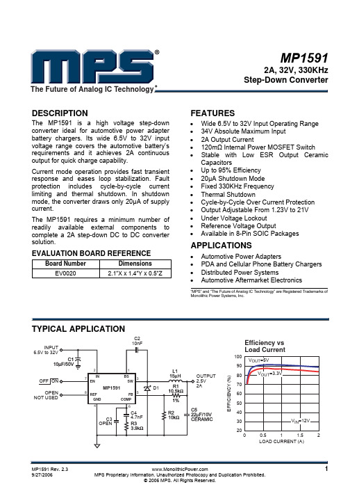
MP15912A, 32V, 330KHz Step-Down ConverterThe Future of Analog IC TechnologyDESCRIPTIONThe MP1591 is a high voltage step-down converter ideal for automotive power adapter battery chargers. Its wide 6.5V to 32V input voltage range covers the automotive battery’s requirements and it achieves 2A continuous output for quick charge capability.Current mode operation provides fast transient response and eases loop stabilization. Fault protection includes cycle-by-cycle current limiting and thermal shutdown. In shutdown mode, the converter draws only 20µA of supply current.The MP1591 requires a minimum number of readily available external components to complete a 2A step-down DC to DC converter solution.EVALUATION BOARD REFERENCEBoard NumberDimensions EV00202.1”X x 1.4”Y x 0.5”ZFEATURES• Wide 6.5V to 32V Input Operating Range • 34V Absolute Maximum Input • 2A Output Current• 120m Ω Internal Power MOSFET Switch• Stable with Low ESR Output CeramicCapacitors• Up to 95% Efficiency • 20µA Shutdown Mode • Fixed 330KHz Frequency • Thermal Shutdown• Cycle-by-Cycle Over Current Protection • Output Adjustable From 1.23V to 21V • Under Voltage Lockout • Reference Voltage Output• Available in 8-Pin SOIC PackagesAPPLICATIONS• Automotive Power Adapters• PDA and Cellular Phone Battery Chargers • Distributed Power Systems • Automotive Aftermarket Electronics“MPS” and “The Future of Analog IC Technology” are Registered Trademarks of Monolithic Power Systems, Inc.TYPICAL APPLICATIONC21009080706050403020E F F I C I E N C Y (%)0.51 1.52LOAD CURRENT (A)Efficiency vs Load CurrentMP1591 – 2A, 32V, 330KHz STEP-DOWN CONVERTERPACKAGE REFERENCE* For Tape & Reel, add suffix –Z (eg. MP1591DN–Z) For RoHS Compliant Packaging, add suffix –LF(eg. MP1591DN–LF–Z) ABSOLUTE MAXIMUM RATINGS (1) IN Supply Voltage........................–0.3V to +34V SW Voltage.............................–1V to V IN + 0.3V BS Voltage....................V SW – 0.3V to V SW + 6V All Other Pins.................................–0.3V to +6V Junction Temperature...............................150°C Lead Temperature....................................260°C Storage Temperature..............–65°C to +150°C Recommended Operating Conditions (2) Input Voltage...................................6.5V to 32V Operating Temperature.............–40°C to +85°C Thermal Resistance (3)θJA θJCSOIC8 (w/ Exposed Pad).......50......10...°C/W SOIC8.....................................90......45...°C/W Notes:1) Exceeding these ratings may damage the device.2) The device is not guaranteed to function outside of itsoperating conditions.3) Measured on approximately 1” square of 1 oz copper.ELECTRICAL CHARACTERISTICSV IN = 12V, T A = +25°C, unless otherwise noted.Parameter Symbol ConditionMinTypMaxUnits Shutdown Supply Current V EN= 0V 20 35 µASupply Current V EN = 5V, V FB = 1.4V 1.0 1.2 mAFeedback Voltage 6.5V ≤ V IN≤ 32V, V COMP < 2V 1.202 1.230 1.258VError Amplifier Voltage Gain 400 V/VError Amplifier Transconductance ∆I C = ±10µA 500 700 1100 µA/VHigh-Side Switch On Resistance (4) 120 mΩLow-Side Switch On Resistance (4)8.5 ΩHigh-Side Switch Leakage Current V EN = 0V, V SW = 0V 0 10 µACurrent Limit (5) 2.53.64.9A Current Sense to COMPTransconductance3.5 A/VOscillation Frequency 280 330 380 KHzShort Circuit Oscillation Frequency V FB = 0V 35 KHzMaximum Duty Cycle (4)V FB = 1.0V 90 %Minimum Duty Cycle (4)V FB = 1.5V 0 %EN Shutdown Threshold Voltage 0.8 1.2 1.6 VEnable Pull-Up Current V EN = 0V 1.8 µAEN UVLO Threshold V EN Rising 2.4 2.6 2.8 VEN UVLO Threshold Hysteresis 250 mVMP1591 – 2A, 32V, 330KHz STEP-DOWN CONVERTERELECTRICAL CHARACTERISTICS (continued)V IN = 12V, T A = +25°C, unless otherwise noted.MaxUnitsMinTypParameter Symbol ConditionThermal Shutdown (4) 160 °CREF Voltage I REF = 0 5.0 VREF Load Regulation (4)∆I REF = 0 to 1mA 100 mVREF Line Regulation (4)I REF = 100µA, V IN = 6.5 to 32V 30 mVNotes:4) These parameters are guaranteed by design, not production tested.5) Equivalent output current = 1.5A ≥ 50% Duty Cycle≤ 50% Duty Cycle2.0AAssumes ripple current = 30% of load current.Slope compensation changes current limit.PIN FUNCTIONSPin # Name Description1 BS High-Side Gate Drive Boost Input. BS supplies the drive for the high-side N-Channel MOSFETswitch. Connect a 10nF or greater capacitor from SW to BS to power the high-side switch.2 IN Power Input. IN supplies the power to the IC, as well as the step-down converter switches.Drive IN with a 6.5V to 32V power source. Bypass IN to GND with a suitably large capacitor toeliminate noise on the input to the IC. See Input Capacitor.3 SW Power Switching Output. SW is the switching node that supplies power to the output. Connectthe output LC filter from SW to the output load. Note that a capacitor is required from SW to BSto power the high-side switch.4 GND Ground. For the MP1591DN, connect the Exposed Pad to pin 4.5 FB Feedback Input. FB senses the output voltage to regulate that voltage. Drive FB with a resistivevoltage divider from the output voltage. The feedback threshold is 1.230V. See Setting theOutput Voltage.6 COMP Compensation Node. COMP is used to compensate the regulation control loop. Connect aseries RC network from COMP to GND to compensate the regulation control loop. In somecases, an additional capacitor from COMP to GND is required. See Compensation.7 EN Enable/UVLO. A voltage greater than 2.8V enables operation. For complete low currentshutdown the EN pin voltage needs to be less than 800mV.8 REF Reference Output. REF is the 5V reference voltage output. It can supply up to 1mA to externalcircuitry. If used, bypass REF to GND with 10nF or greater capacitor. Leave REF unconnectedif not used.MP1591 – 2A, 32V, 330KHz STEP-DOWN CONVERTEROPERATIONThe MP1591 is a current mode step-down regulator. It regulates input voltages from 6.5V to 32V down to an output voltage as low as 1.230V and is able to supply up to 2A of load current.The MP1591 uses current-mode control to regulate the output voltage. The output voltage is measured at FB through a resistive voltage divider and amplified through the internal error amplifier. The output current of the transconductance error amplifier is presented at COMP where a network compensates the regulation control system.The voltage at COMP is compared to the switch current measured internally to control the output voltage. The converter uses an internal N-Channel MOSFET switch to step-down the input voltage to the regulated output voltage. Since the MOSFET requires a gate voltage greater than the input voltage, a boost capacitor connected between SW and BS drives the gate. The capacitor is internally charged while SW is low. An internal 10Ω switch from SW to GND is used to insure that SW is pulled to GND when the switch is off to fully charge the BS capacitorCOMPIN EN GNDSWBSREF FBFigure 1—Functional Block DiagramMP1591 – 2A, 32V, 330KHz STEP-DOWN CONVERTERAPPLICATION INFORMATIONCOMPONENT SELECTIONSetting the Output VoltageThe output voltage is set using a resistive voltage divider from the output voltage to FB. The voltage divider divides the output voltage down by the ratio:)2R 1R (2R V V OUT FB +×=Where V FB is the feedback voltage and V OUT isthe output voltage. Thus the output voltage is:2R )2R 1R (230.1V OUT +×= A typical value for R2 can be as high as 100k Ω, but 10k Ω is recommended. Using that value, R1 is determined by:)230.1V (18.81R OUT −×≅For example, for a 3.3V output voltage, R2 is 10k Ω, and R1 is 17k Ω.Inductor (L1)The inductor is required to supply constant current to the output load while being driven by the switched input voltage. A larger value inductor results in less ripple current that results in lower output ripple voltage. However, the larger value inductor has a larger physical size, higher series resistance, and/or lower saturation current. Choose an inductor that does not saturate under the worst-case load conditions. A good rule to use for determining the inductance is to allow the peak-to-peak ripple current in the inductor to be approximately 30% of the maximum load current that the IC can provide. Also, make sure that the peak inductor current (the load current plus half the peak-to-peak inductor ripple current) is below the 2.3A minimum current limit.The inductance value can be calculated by the equation:)I f V ()V V (V 1L IN OUT IN OUT ∆××−×=Where V IN is the input voltage, f is the switching frequency and ∆I is the peak-to-peak inductor ripple current.Table 1 lists a number of suitable inductors from various manufacturers.Table 1—Inductor Selection GuidePackage Dimensions(mm) Vendor/ Model Core Type CoreMaterial W L H SumidaCR75 Open Ferrite 7.0 7.8 5.5 CDH74 Open Ferrite 7.3 8.0 5.2 CDRH5D28Shielded Ferrite 5.5 5.7 5.5 CDRH5D28Shielded Ferrite 5.5 5.7 5.5 CDRH6D28Shielded Ferrite 6.7 6.7 3.0 CDRH104R Shielded Ferrite 10.110.0 3.0Toko D53LC Type AShieldedFerrite 5.0 5.0 3.0 D75C Shielded Ferrite 7.6 7.6 5.1 D104C Shielded Ferrite 10.010.0 4.3 D10FL Open Ferrite 9.7 1.5 4.0 CoilcraftDO3308 Open Ferrite 9.4 13.0 3.0 DO3316 Open Ferrite 9.4 13.0 5.1Input Capacitor (C1)The input current to the step-down converter is discontinuous, and so a capacitor is required to supply the AC current to the step-down converter while maintaining the DC input voltage. A low ESR capacitor is required to keep the noise at the IC to a minimum. Ceramic capacitors are preferred, but tantalum or low ESR electrolytic capacitors may also suffice.MP1591 – 2A, 32V, 330KHz STEP-DOWN CONVERTERThe input capacitor value should be greater than 10µF. The capacitor can be electrolytic, tantalum or ceramic. However, since it absorbs the input switching current it requires an adequate ripple current rating. Its RMS current rating should be greater than approximately 1/2 of the DC load current.For insuring stable operation C1 should be placed as close to the IC as possible. Alternately, a smaller high quality ceramic 0.1µF capacitor may be placed closer to the IC and a larger capacitor placed farther away. If using this technique, it is recommended that the larger capacitor be a tantalum or electrolytic type. All ceramic capacitors should be placed close to the MP1591.Output Capacitor (C5)The output capacitor is required to maintain the DC output voltage. Low ESR capacitors are preferred to keep the output voltage ripple low. The characteristics of the output capacitor also affect the stability of the regulation control system. Ceramic, tantalum or low ESR electrolytic capacitors are recommended. In the case of ceramic capacitors, the impedance at the switching frequency is dominated by the capacitance, and so the output voltage ripple is mostly independent of the ESR. The output voltage ripple is estimated to be:2SWLCIN RIPPLE ff V 4.1V ⎟⎟⎠⎞⎜⎜⎝⎛××≅ Where V RIPPLE is the output ripple voltage, f LC isthe resonant frequency of the LC filter, f SW is the switching frequency.In the case of tantalum or low-ESR electrolytic capacitors, the ESR dominates the impedance at the switching frequency, and so the output ripple is calculated as:ESR RIPPLE R I V ×∆≅Where V RIPPLE is the output voltage ripple and R ESR is the equivalent series resistance of the output capacitors.Output Rectifier Diode (D1)The output rectifier diode supplies the current to the inductor when the high-side switch is off. To reduce losses due to the diode forward voltage and recovery times, use a Schottky rectifier. Table 2 provides some recommended Schottky rectifiers based on the maximum input voltage and current rating.Table 2—Diode Selection Guide2A Load Current 3A Load Current V IN (Max)Part Number Vendor PartNumberVendor15V 30BQ15 4B220 1 B320 1SK23 6 SK33 1, 620V SR22 6 SS32 3 20BQ030 4 B330 1 B230 1 B340L 1SK23 6 MBRD330 4, 5SR23 3, 6 SK33 1, 6 30V SS23 2, 3 SS33 2, 3 21DQ04 4 B340L 1 MBRS240L 5 MBRS340 4SK24 6 SK34 1, 6 34VSS24 2, 3 SS34 2, 3Table 3 lists manufacturer’s websites.Table 3—Schottky Diode Manufacturers# Vendor Web Site 1 Diodes, Inc.2 Fairchild Semiconductor 3 General Semiconductor 4 International Rectifier 5 On Semiconductor 6 Pan Jit InternationalChoose a rectifier whose maximum reverse voltage rating is greater than the maximum input voltage, and whose current rating is greater than the maximum load current.MP1591 – 2A, 32V, 330KHz STEP-DOWN CONVERTERCompensationThe system stability is controlled through the COMP pin. COMP is the output of the internal transconductance error amplifier. A series capacitor-resistor combination sets a pole-zero combination to control the characteristics of the control system. The DC loop gain is:LOAD CS VEA OUTREFVDC R G A V V A ×××=Where V REF is the feedback threshold voltage, 1.230V, A VEA is the transconductance error amplifier voltage gain, 400 V/V, and G CS is the current sense gain (roughly the output current divided by the voltage at COMP), 3.5 A/V. The system has 2 poles of importance; one is due to the compensation capacitor (C4) and the other is due to the output capacitor (C5). These are:)4C A 2(G f VEA MEA1P ××π=Where f P1 is the first pole, and G MEA is the error amplifier transconductance (770µS) and)5C R 2(1f LOAD 2P ××π=The system has one zero of importance due to the compensation capacitor (C4) and the compensation resistor (R3) which is)4C 3R 2(1f 1Z ××π=If large value capacitors with relatively high equivalent-series-resistance (ESR) are used, the zero due to the capacitance and ESR of the output capacitor can be compensated by a third pole set by R3 and C3)3C 3R 2(1f 3P ××π=The system crossover frequency f C, (the frequency where the loop gain drops to 1, or 0dB) is important. A good rule of thumb is to set the crossover frequency to approximately one tenth of the switching frequency. In this case, the switching frequency is 330KHz, so use a crossover frequency of 33KHz. Lower crossover frequencies result in slower response and worse transient load recovery. Higher crossover frequencies can result in instability. Choosing the Compensation Components The values of the compensation components given in Table 4 yield a stable control loop for the output voltage and given capacitor. Table 4—Compensation Values for Typical Output Voltage/Capacitor CombinationsV OUT C5R3 C3 C42.5V 22µF Ceramic3.9k Ω None4.7nF 3.3V 22µF Ceramic5.1k Ω None 3.9nF 5V 22µF Ceramic 7.5k Ω None 2.7nF 12V 22µF Ceramic 18k Ω None 1.2nF 2.5V 47µF SP-Cap 8.2k Ω None 2.2nF 3.3V 47µF SP-Cap 10k Ω None 2.2nF 5V 47µF SP-Cap 16k Ω None 1.5nF 12V 47µF SP-Cap 36k Ω None 1nF 2.5V 560µF/6.3V, AL30m Ω ESR 100k Ω 150pF 1nF 3.3V 560µF/6.3V, AL 30m Ω ESR 120k Ω 120pF 1nF 5V 470µF/10V, AL 30m Ω ESR 150k Ω 82pF 1nF 12V220µF/25V, AL 30m Ω ESR180k Ω 33pF 1nFNote: “AL” = ElectrolyticMP1591 – 2A, 32V, 330KHz STEP-DOWN CONVERTERTo optimize the compensation components that are not listed in Table 4, use the following procedure.Choose the compensation resistor to set the desired crossover frequency. Determine the value by the following equation:REFCS EA COUT V G G f V 5C 23R ×××××π=Putting in the know constants and setting the crossover frequency to the desired 33KHz:OUT 7V 5C 1088.63R ×××≅Choose the compensation capacitor to set the zero below one fourth of the crossover frequency. Determine the value by the following equation:3R 1093.1f 3R 24C 5C−×≈××π> Determine if the second compensationcapacitor, C3, is required. It is required if the ESR zero of the output capacitor occurs at less than four times the crossover frequency, or1f R 5C 8C ESR ≥×××πIf this is the case, then add the second compensation resistor. Determine the value by the equation:3R R 5C 3C )MAX (ESR ×=Where R ESR(MAX)is the maximum ESR of the output capacitor.Example:V OUT = 5V, C5 = 22µF Ceramic (ESR = 10m Ω)R3 ≈ 6.88x10⁷ (22x10-6) (5) = 7568Ω Use the nearest standard value of 7.5k Ω.C4 > 1.93x10⁻⁵ / 7.5K = 2.57nFUse standard value of 2.7nF.8π x C5 x R ESR x f C = 0.22, which is less than 1. Therefore, no second compensation capacitor (C3) is required.External Bootstrap DiodeIt is recommended that an external bootstrap diode be added when the system has a 5V fixed input or the power supply generates a 5V output. This helps improve the efficiency of the regulator. The bootstrap diode can be a low cost one such as IN4148 or BAT54.10nFFigure 2—External Bootstrap Diode This diode is also recommended for high duty cycle operation (whenINOUTV V >65%) and high output voltage (V OUT >12V) applications.MP1591 – 2A, 32V, 330KHz STEP-DOWN CONVERTERTYPICAL APPLICATION CIRCUITSC2Figure 3—MP1591 with Murata 22µF / 10V Ceramic Output CapacitorC2Figure 4—MP1591 with Panasonic 47µF / 6.3V Special Polymer Output CapacitorMP1591 – 2A, 32V, 330KHz STEP-DOWN CONVERTERPACKAGE INFORMATIONSOIC8DETAIL "A" 5) DRAWING CONFORMS TO JEDEC MS-012, VARIATION AA.6) DRAWING IS NOT TO SCALE.MP1591 – 2A, 32V, 330KHz STEP-DOWN CONVERTERNOTICE: The information in this document is subject to change without notice. Users should warrant and guarantee that thirdparty Intellectual Property rights are not infringed upon when integrating MPS products into any application. MPS will not assume any legal responsibility for any said applications.MP1591 Rev. 2.3 119/27/2006 MPS Proprietary Information. Unauthorized Photocopy and Duplication Prohibited.© 2006 MPS. All Rights Reserved.SOIC8E (WITH EXPOSED PAD)TOP VIEW FRONT VIEWBOTTOM VIEWNOTE:1) CONTROL DIMENSION IS IN INCHES. DIMENSION IN BRACKET IS IN MILLIMETERS.2) PACKAGE LENGTH DOES NOT INCLUDE MOLD FLASH, PROTRUSIONS OR GATE BURRS.3) PACKAGE WIDTH DOES NOT INCLUDE INTERLEAD FLASH OR PROTRUSIONS.4) LEAD COPLANARITY (BOTTOM OF LEADS AFTER FORMING) SHALL BE 0.004" INCHES MAX.5) DRAWING CONFORMS TO JEDEC MS-012, VARIATION BA.6) DRAWING IS NOT TO SCALE.RECOMMENDED LAND PATTERNPIN 1 IDDETAIL "A"o元器件交易网。

GM2001无电感5V输出电荷泵型降压稳压芯片1、产品简介GM2001是一款5V输出电荷泵型降压稳压芯片,输入电压范围宽达6~28V,最大输出电流能力达150mA,内部采用固定900KHz开关频率,同时芯片内部还集成了短路保护、过流保护、过热保护等单元提升可靠性,ESD HBM高达±6000V。
与传统的降压芯片相比,GM2001无需外围的电感和肖特基二极管,应用方案简洁,仅需要3个外围电容。
同时由于无电感器件,芯片的EMI要大幅度低于有电感的开关电源方案,并且在输出电压纹波方面也具有优越的性能。
而与LDO类型的稳压芯片相比,GM2001在效率方面具有极高优势,当输入电压高于10.5V时,转换效率会增加一倍,最高转换效率高达81%,但输出电压噪声又不会增加过多,因此GM2001可以直接取代LDO。
尤其在智能电表和水表及其通信模块等工业领域,GM2001是一款具有优越性价比的稳压电源芯片。
2、应用范围■工业控制■电表、水表、气表■汽车电子3、特色■工作电压:6~28V■输出电压:5V±5%■输出电流:150mA max■ESD HBM±6KV■固定频率:900KHz■低纹波:<8mV■过流保护■过热保护■短路保护■温度范围-40℃to+85℃■应用成本低:无需电感、肖特基二极管、外围器件极少4、封装类型■EMSOP85、功能引脚定义图1、GM2001Top View 序号名称说明1VIN输入引脚2NC3GND接地4CP飞电容正端5CN飞电容负端6NC7NC8VOUT输出引脚注意:EP必须在PCB设计时接露铜散热区6、典型应用电路图2典型应用电路图7、极限参数符号说明大小单位VCC最大输入端电压30VTj最大结温170℃Θja热阻40℃/W Tstg储存温度-60~160℃Pd最大消耗功率(ESOP8) 1.5WESD HBM6000V8、电气特性(各外围参数如图2所示,VDD=12V,TA=+25℃,除非特别注明)参数符号条件最小典型最大单位输入电压VCC628V输出电压VOUT VCC:7~28V 4.75 5.3V电压精度△Vout±5%静态电流Iin空载 1.1mA输出电流Iout100150mA负载调整Vrl负载电流0~100mA 3.7mV/mA 负载电流50~100mA1mV/mA 输入调整Vri VCC:7~28V1mV/V 开关频率Fosc900KHz电源抑制PSRR1Hz~10Mhz50dB输出纹波Riple负载电流=100mA57mV负载电流=15mA1mV短路电流Ishort输出短路到地22mA过流保护Ip200mA热保护点Tp150℃Thys20℃热保护迟滞9、典型特性图3、转换效率VS.输入电压(Iout=100mA)图4、转换效率VS.输出电流(VIN=12V)图5、输入端纹波(Iout=100mA)图6、输出端纹波(Iout=100mA)图7、负载响应CH1:Iout25mA/Div CH2:Vout20mV/Div100us/Div图8、输入响应图9、开关频率VS.温度图10、电源抑制比图11、输出纹波频谱(Iout=100mA)图12、输出纹波频谱(Iout=10mA)10、应用说明概述GM2001是一款电荷泵降压型稳压芯片,可以提供稳定的5V输出,最大输出电流能力达150mA。
MP2105DJ-LF-PMP21051MHz, 800mA Synchronous Step-Down ConverterThe Future of Analog IC Technology DESCRIPTIONThe MP2105 is a 1MHz constant frequency,current mode, PWM step-down converter. The device integrates a main switch and a synchronous rectifier for high efficiency without an external Schottky diode. It is ideal for powering portable equipment that runs from a single cell Lithium-Ion (Li+) battery. The MP2105 can supply 800mA of load current from a 2.5V to 6V input voltage. The output voltage can be regulated as low as 0.6V. The MP2105 can also run at 100% duty cycle for low dropout applications.The MP2105 is available in a low profile (1mm) 5-pin, TSOT and 10-pin, MSOP packages.FEATURES• High Efficiency: Up to 95%• 1MHz Constant Switching Frequency • 800mA Available Load Current • 2.5V to 6V Input Voltage Range • Output Voltage as Low as 0.6V • 100% Duty Cycle in Dropout • Current Mode Control • Short Circuit Protection • Thermal Fault Protection • <0.1μA Shutdown Current• Space Saving 5-Pin TSOT23 and 10-pinMSOP PackagesAPPLICATIONS• Cellular and Smart Phones• Microprocessors and DSP Core Supplies • PDAs • MP3 Players• Digital Still and Video Cameras • Portable InstrumentsAll MPS parts are lead-free and adhere to the RoHS directive. For MPS green status, please visit MPS website under Products, Quality Assurance page.“MPS” and “The Future of Analog IC Technology” are registered trademarks of Monolithic Power Systems, Inc.TYPICAL APPLICATIONE F F I C I E N C Y (%)101001000LOAD CURRENT (mA)MP2105-EC01Efficiency vs Load CurrentMP2105 – 1MHz 800mA SYNCHRONOUS STEP-DOWN CONVERTERORDERING INFORMATIONPart Number Package Top Marking Free Air Temperature (T A) MP2105DJ*TSOT23-5 C5 –40°C to +85°CMP2105DK**MSOP10 2105D –40°C to +85°C* For Tape & Reel, add suffix –Z (g. MP2105DJ–Z).For RoHS compliant packaging, add suffix –LF (e.g. MP2105DJ–LF–Z)** For Tape & Reel, add suffix –Z (g. MP2105DK–Z).For RoHS compliant packaging, add suffix –LF (e.g. MP2105DK–LF–Z)PACKAGE REFERENCEABSOLUTE MAXIMUM RATINGS (1) V IN to GND..................................–0.3V to +6.5V V SW to GND...........................–0.3V to V IN +0.3V V FB, V EN to GND..........................–0.3V to +6.5V Continuous Power Dissipation (T A = +25°C) (2) TSOT23-5………………………………....0.56W MSOP10…………………………………....0.83W Junction Temperature.............................+150°C Lead Temperature..................................+260°C Storage Temperature .............–65°C to +150°C Recommended Operating Conditions (3) Supply Voltage V IN.............................2.5V to 6V Output Voltage V OUT...........................0.6V to 6V Operating Junct. Temp............-40°C to +125°C Thermal Resistance (4)θJA θJCTSOT23-5..............................220....110..°C/W MSOP10................................150.....65...°C/W Notes:1) Exceeding these ratings may damage the device.2) The maximum allowable power dissipation is a function of themaximum junction temperature T J (MAX), the junction-to-ambient thermal resistance θJA, and the ambient temperature T A. The maximum allowable continuous power dissipation at any ambient temperature is calculated by P D (MAX) = (T J (MAX)-T A)/θJA. Exceeding the maximum allowable power dissipation will cause excessive die temperature, and the regulator will go into thermal shutdown. Internal thermal shutdown circuitry protects the device from permanent damage.3) The device is not guaranteed to function outside of itsoperating conditions.4) Measured on JESD51-7, 4-layer PCB.MP2105 – 1MHz 800mA SYNCHRONOUS STEP-DOWN CONVERTER ELECTRICAL CHARACTERISTICS (5)V IN = V EN = 3.6V, T A = +25°C, unless otherwise noted.Parameter SymbolCondition MinTypMaxUnitsSupply Current V EN = V IN, V FB = 0.65V 440 600 μA Shutdown Current V EN = 0V, V IN = 6V 0.10 1 μAIN Undervoltage Lockout Threshold RisingEdge 2.15 2.30 2.40 VIN Undervoltage LockoutHysteresis55 mVT A = +25°C 0.588 0.600 0.612Regulated FB Voltage V FB–40°C ≤ T A≤ +85°C 0.582 0.600 0.618VFB Input Bias Current V FB = 0.65V –50 0.5 +50 nA PFET On Resistance I SW=100mA 0.42 ΩNFET On Resistance I SW=–100mA 0.26 ΩSW Leakage Current V EN = 0V, V IN = 6V,V SW = 0V or 6V–1 +1 μAPFET Current Limit Duty Cycle = 100%,Current Pulse Width < 1ms1.2 1.6 AOscillator Frequency f OSC0.85 1.05 1.3 MHz Thermal Shutdown TripThreshold145 °CEN Trip Threshold –40°C ≤ T A≤+85°C 0.3 0.96 1.5 V EN Input Current V EN = 0V to 6V –1 +1 μA Notes:5) 100% production test at +25°C. Specifications over the temperature range are guaranteed by design and characterization.MP2105 – 1MHz 800mA SYNCHRONOUS STEP-DOWN CONVERTERPIN FUNCTIONSMSOP Pin # TSOT Pin #Name Description8 1 ENRegulator Enable Control Input. Drive EN above 1.5V to turn on the MP2105.Drive EN below 0.3V to turn it off (shutdown current < 0.1μA).3 2 GND Ground.9 3 SWPower Switch Output. Inductor connection to drains of the internal PFET andNFET switches.1 4 IN Supply Input. Bypass to GND with a 2.2μF or greater ceramic capacitor.5 5 FBFeedback Input. Connect FB to the center point of the external resistor divider.The feedback threshold voltage is 0.6V.2, 4, 6, 7 NC No Connect 10 PGND Power GroundMP2105 – 1MHz 800mA SYNCHRONOUS STEP-DOWN CONVERTERTYPCIAL PERFORMANCE CHARACTERISTICSV IN = 3.3V, V OUT = 1.8V, L1 = 4.7μH, C1 = 4.7μF, C3 = 10μF, T A = +25°C, unless otherwise noted.MP2105-TPC03Load Transient(I OUT =0mA to 500mA step)Light Load Operation(I OUT =0mA)F E ED B A C K V O L T AG E (V )-40+200+40+60+80+100-40+200-20+40+60+80+100TEMPERATURE (°C)MP2105-TPC01Feedback Voltage vs TemperatureE F F I C I E N C Y (%)101001000LOAD CURRENT (mA)MP2105-EC01E F F I C I E N C Y (%)LOAD CURRENT (mA)MP2105-TPC041.101.081.061.041.021.000.980.960.94S W I T C H I N G F R E Q U E N C Y (M H z )TEMPERATURE (°C)MP2105-TPC02Switching Frequency vs TemperatureMP2105-EC02V OUT 100mV/div.I OUT 0.5A/div.V OUT 10mV/div.I L0.2A/div.SW 2V/div.MP2105 – 1MHz 800mA SYNCHRONOUS STEP-DOWN CONVERTERTYPCIAL PERFORMANCE CHARACTERISTICS (continued)V IN = 3.3V, V OUT = 1.8V, L1 = 4.7μH, C1 = 4.7μF, C3 = 10μF, T A = +25°C, unless otherwise noted.MP2105-TPC09Short Circuit Protection(No Load)MP2105-TPC07Heavy Load OperationI OUT= 800mAMP2105-TPC10Short Circuit Recovery (No Load)MP2105-TPC08Startup from ShutdownV OUT 10mV/div.I L0.2A/div.L =0SW 2V/div.V OUT 1V/div.I L0.5A/div.V OUT 1V/div.I L0.5A/div.V EN 2V/div.V OUT 1V/div.I L0.5A/div.MP2105 – 1MHz 800mA SYNCHRONOUS STEP-DOWN CONVERTEROPERATIONThe MP2105 is a constant frequency current mode PWM step-down converter. The MP2105 is optimized for low voltage, Li-Ion battery powered applications where high efficiency and small size are critical. The MP2105 uses an external resistor divider to set the output voltage from 0.6V to 6V. The device integrates both a main switch and a synchronous rectifier, which provides high efficiency and eliminatesan external Schottky diode. The MP2105 can achieve 100% duty cycle. The duty cycle D of a step-down converter is defined as:%100V V %100f T D INOUTOSC ON ×≈××= where T ON is the main switch on time, and f OSC is the oscillator frequency (1MHz).INENFBGNDSWMP2105_BD01Figure 1—Function Block DiagramMP2105 – 1MHz 800mA SYNCHRONOUS STEP-DOWN CONVERTERCurrent Mode PWM ControlSlope compensated current mode PWM control provides stable switching and cycle-by-cycle current limit for superior load and line response and protection of the internal main switch and synchronous rectifier. The MP2105 switches at a constant frequency (1MHz) and regulates the output voltage. During each cycle the PWM comparator modulates the power transferred to the load by changing the inductor peak current based on the feedback error voltage. During normal operation, the main switch is turned on for a certain time to ramp the inductor current at each rising edge of the internal oscillator, and switched off when the peak inductor current is above the error voltage. When the main switch is off, the synchronous rectifier will be turned on immediately and stay on until either the next cycle starts. Dropout OperationThe MP2105 allows the main switch to remain on for more than one switching cycle and increases the duty cycle while the input voltage is dropping close to the output voltage. When the duty cycle reaches 100%, the main switch is held on continuously to deliver current to the output up to the PFET current limit. The output voltage then is the input voltage minus the voltage drop across the main switch and the inductor.Short Circuit ProtectionThe MP2105 has short circuit protection. When the output is shorted to ground, the oscillator frequency is reduced to prevent the inductor current from increasing beyond the PFET current limit. The PFET current limit is also reduced to lower the short circuit current. The frequency and current limit will return to the normal values once the short circuit condition is removed and the feedback voltage reaches 0.6V.Maximum Load CurrentThe MP2105 can operate down to 2.5V input voltage; however the maximum load current decreases at lower input due to large IR drop on the main switch and synchronous rectifier. The slope compensation signal reduces the peak inductor current as a function of the duty cycle to prevent sub-harmonic oscillations at duty cycles greater than 50%. Conversely the current limit increases as the duty cycle decreaseMP2105 – 1MHz 800mA SYNCHRONOUS STEP-DOWN CONVERTERPPLICATION INFORMATIONOutput Voltage SettingThe external resistor divider sets the output voltage (see Figure 3). The feedback resistor R1 also sets the feedback loop bandwidth with the internal compensation capacitor (see Figure 1). Choose R1 around 500k Ω for optimal transient response. R2 is then given by:1V6.0V 1R 2R OUT−=Table 1—Resistor Selection vs. OutputVoltage SettingV OUT R1 R2 1.2V 499k Ω (1%) 499k Ω (1%) 1.5V 499k Ω (1%) 332k Ω (1%) 1.8V 499k Ω (1%) 249k Ω (1%) 2.5V 499k Ω (1%)158k Ω (1%)Inductor SelectionA 1μH to 10μH inductor with DC current rating at least 25% higher than the maximum load current is recommended for most applications. For best efficiency, the inductor DC resistance shall be <200m Ω. See Table 2 for recommended inductors and manufacturers. For most designs, the inductance value can be derived from the following equation:()OSCL IN OUT IN OUT f I V V V V L ×Δ×−×=where ΔI L is Inductor Ripple Current. Choose inductor ripple current approximately 30% of the maximum load current, 800mA.The maximum inductor peak current is:2I I I LLOAD )MAX (L Δ+= Under light load conditions below 100mA, larger inductance is recommended for improved efficiency. Table 3 lists inductors recommended for this purpose.Table 2—Suggested Surface Mount InductorsManufacturer Part Number Inductance (μH)Max DCR (Ω)SaturationCurrent (A)DimensionsL x W x H (mm3)Coilcraft D01605T-472 4.7 0.150 1.20 5.4 x 4.2 x 1.8 Toko D52LC 4.7 0.087 1.14 5 x 5 x 2 Sumida CR43-4R7 4.7 0.109 1.15 4.3 x 4.8 x 3.5Table 3—Inductors for Improved Efficiency at 25mA, 50mA, under 100mA Load.Manufacturer Part Number Inductance (μH)Max DCR (Ω)SaturationCurrent (A)I RMS (A)Coilcraft DO1605T-103MX10 0.3 1.0 0.9Murata LQH4C100K04 10 0.2 1.2 0.8 Sumida CR32-100 10 0.2 1.0 0.7 Sumida CR54-100 10 0.1 1.2 1.4Input Capacitor SelectionThe input capacitor reduces the surge current drawn from the input and switching noise from the device. The input capacitor impedance at the switching frequency shall be less than input source impedance to prevent high frequency switching current passing to the input. Ceramic capacitors with X5R or X7R dielectrics are highly recommended because of their low ESR and small temperature coefficients. For most applications, a 4.7μF capacitor is sufficient. Output Capacitor SelectionThe output capacitor keeps output voltage ripple small and ensures regulation loop stable. The output capacitor impedance shall be low at the switching frequency. Ceramic capacitors with X5R or X7R dielectrics are recommended. The output ripple ΔV OUT is approximately:()⎟⎟⎠⎞⎜⎜⎝⎛××+×××−×≤Δ3Cf81ESRLfVVVVVOSCOSCINOUTINOUTOUTPCB layout guidePCB layout is very important to achieve stable operation. It is highly recommended to duplicate EVB layout for optimum performance.If change is necessary, please follow these guidelines and take figure 2 for reference.1) Keep the path of switching current short andminimize the loop area formed by Input cap,high-side MOSFET and low-side MOSFET. 2) Bypass ceramic capacitors are suggested tobe put close to the Vin Pin. 3) Ensure all feedback connections are shortand direct. Place the feedback resistors andcompensation components as close to thechip as possible.4) Route SW away from sensitive analog areassuch as FB.5) Connect IN, SW, and especially GNDrespectively to a large copper area to coolthe chip to improve thermal performance andlong-term reliability.INPUT2.5V - 6VOFF ONFigure 2 —MP2105 Typical Application CircuitTop Layer Bottom Layer Figure 3—MP2105 Suggested Layout (TQFN)PACKAGE INFORMATIONTSOT23-5NOTICE: The information in this document is subject to change without notice. Please contact MPS for current specifications. Users should warrant and guarantee that third party Intellectual Property rights are not infringed upon when integrating MPS products into any application. MPS will not assume any legal responsibility for any said applications.MSOP10BOTTOM VIEWFRONT VIEW SIDE VIEWGAUGE PLANETOP VIEWNOTE:1) CONTROL DIMENSION IS IN INCHES. DIMENSION IN BRACKET IS IN MILLIMETERS.2) PACKAGE LENGTH DOES NOT INCLUDE MOLD FLASH, PROTRUSION OR GATE BURR.3) PACKAGE WIDTH DOES NOT INCLUDE INTERLEAD FLASH OR PROTRUSION.4) LEAD COPLANARITY (BOTTOM OF LEADS AFTER FORMING) SHALL BE 0.004" INCHES MAX.5) PIN 1 IDENTIFICATION HAS THE HALF OR FULL CIRCLE OPTION. 6) DRAWING MEETS JEDEC MO-817, VARIATION BA. 7) DRAWING IS NOT TO SCALE.RECOMMENDED LAND PATTERNMP2105DJ-LF-P。
87A、150V N沟道增强型场效应管SVGP159R3NL5A N沟道增强型功率MOS场效应晶体管采用士兰的LVMOS 工艺技术制造。
先进的工艺及元胞结构使得该产品具有较低的导通电阻、优越的开关性能及很高的雪崩击穿耐量。
该产品可广泛应用于不间断电源及逆变器系统的电源管理领域。
特点♦87A,150V,R DS(on)(典型值)=7.9 mΩ@V GS=10V♦低栅极电荷量♦低反向传输电容♦开关速度快♦提升了dv/dt能力♦100%雪崩测试♦无铅管脚镀层♦符合RoHS环保标准关键特性参数产品规格分类极限参数(除非特殊说明,T=25︒C)A热特性电气参数(除非特殊说明,T=25︒C)J静态参数动态参数反向二极管特性参数注:1. 脉冲时间5µs;2. 耗散功率值会随着温度变化而变化,当大于25︒C时耗散功率值随着温度每上升1度减少1.14W/︒C;3. 脉冲测试:脉冲宽度≤300μs,占空比≤2%;4. 基本上不受工作温度的影响。
典型特性曲线典型特性曲线(续)典型特性曲线(续)典型测试电路V DSV GS 10V栅极电荷量测试电路及波形图开关时间测试电路及波形图LDDV V E AS 测试电路及波形图V DDV LBV DSSI ASV DDtpTimeV DS(t)I D(t)E AS =12LI AS 2BV DSS BV DSS V DD封装外形图重要注意事项:1. 士兰保留说明书的更改权,恕不另行通知。
2. 客户在下单前应获取我司最新版本资料,并验证相关信息是否最新和完整。
产品应用前请仔细阅读说明书,包括其中的电路操作注意事项。
3. 我司产品属于消费类电子产品或其他民用类电子产品。
4. 在应用我司产品时请不要超过产品的最大额定值,否则会影响整机的可靠性。
任何半导体产品特定条件下都有一定的失效或发生故障的可能,买方有责任在使用我司产品进行系统设计、试样和整机制造时遵守安全标准并采取安全措施,以避免潜在失败风险可能造成人身伤害或财产损失情况的发生。
EV1593DN-00A (MP1593)4.75V to 28V Input, Up to 3A Output Step-Down DC/DC ConverterEVALUATION BOARD - INITIAL RELEASEMonolithic Power SystemsGENERAL DESCRIPTIONThe EV1593DN-00A is the Evaluation Board forMPS’ MP1593 Step-Down DC/DC Converter. It features a wide supply range of 4.75V to 28V and a continuous output current up to 3A. The output voltage is set to 3.3V, but can be easily adjusted to other levels from 1.22V. A 385KHz high switching frequency allows the use of small, low cost capacitors and inductors. Current mode control and an integrated power MOSFET minimize component count, board area, and solution cost. Fault condition protection includes cycle-by-cycle current limiting, thermal shutdown, and under-voltage lockout. Internal soft-start reduces the turn-on stress. The small but thermally enhanced 8-pin SOIC package minimizes board area and provides excellent thermal management.ELECTRICAL SPECIFICATIONParameter Symbol Value Units Supply Voltage V IN 4.75 – 28VOutput Voltage V OUT 3.3 V Output CurrentI OUT 0 – 3AFEATURES• Up to 3A Output Current• Wide 4.75 to 28V Operating Input Range • Monolithic Buck with 100m Ω Internal FET • Fixed 385KHz Frequency• All Ceramic Input and Output Capacitors • Programmable Soft-Start• Programmable Input Under-Voltage LockoutAPPLICATIONS• Distributed Power Systems • Battery Charger• Pre-Regulator for Linear Regulators, “MPS”, “Monolithic Power Systems”, and “The Future of Analog ICTechnology” are Registered Trademarks of Monolithic Power Systems, Inc.EV1593DN-00A EVALUATION BOARD(2.1”X x 1.3”Y x 0.4”Z)Board NumberMPS IC NumberEV1593DN-00A MP1593E F F I C I E N C Y (%)10095908580757065605550LOAD CURRENT (mA)EV1593_TAC _EC01Efficiency vsLoad Current500100015002000250030003500EV1593DN-00A – 4.75V-28V INPUT, UP TO 3A OUTPUT STEP-DOWN CONVERTEREVALUATION BOARD - INITIAL RELEASEEVALUATION BOARD SCHEMATICEV1593_S01SWGNDGNDVIN EN SSVOUTEV1593DN-00A BILL OF MATERIALSQty Ref DescriptionPackage Manufacturer Part Number 1 C1 Ceramic Capacitor, 22nF, 50V, X7R 0805 Any2 C2, C8 Ceramic Capacitor, 10µF, 50V, Y5V 1210 Murata GRM32DF51H106ZA01L 1 C3 Ceramic Capacitor, 8.2nF, 50V, X7R 0603 Any 0 C4, C7 Open2 C5, C9 Ceramic Capacitor, 22µF, 16V, X5R 1210 Taiyo Yuden EMK3Z5BJ226MM 1 C6 Ceramic Capacitor, 0.1µF, 50V, X7R 0805 Any 1 L1 Inductor, 10µH, 4A Sumida CDRH8D43-100NC 0 D1 Schottky Diode, 40V, 3A SMA Diodes Inc. B340A 1 U1 28V, 3A, Step Down Converter SOIC8 MPS MP1593DN 1 R1 Resistor, 16.9k Ω, 1% 0603 Any 1 R2 Resistor, 5.6k Ω, 5% 0603 Any 1 R3 Resistor, 10k Ω, 1% 0603 Any 0 R4 Open 0 R5 OpenEV1593DN-00A – 4.75V-28V INPUT, UP TO 3A OUTPUT STEP-DOWN CONVERTEREVALUATION BOARD - INITIAL RELEASETYPICAL PERFORMANCE CHARACTERISTICS10095908580757065605550E F F I C I E N C Y (%)500100015002000250030003500LOAD CURRENT (mA)EV1593_TPC05Efficiency vs Load CurrentLOAD CURRENT (mA)EV1593_TPC06Efficiency vs Load Current500100015002000250030003500V OUT 1V/Div.I L1A/Div.I L1A/Div.V OUT10mV/Div.V SW 10V/Div.V IN100mV/Div.EV1593-WF03Soft-StartWaveforms V OUT 1V/Div.I L1A/Div.4ms/Div.V IN = 12V, V OUT = 3.3V, 1A - 2A STEPEV1593-WF01Load Transient WaveformsEV1593-WF04Switching WaveformsEV1593-WF02Turn Off WaveformsEV1593DN-00A – 4.75V-28V INPUT, UP TO 3A OUTPUT STEP-DOWN CONVERTEREVALUATION BOARD - INITIAL RELEASE PRINTED CIRCUIT BOARD LAYOUTFigure 1—Top Silk Layer Figure 2—Top LayerFigure 3— Bottom LayerEV1593DN-00A – 4.75V-28V INPUT, UP TO 3A OUTPUT STEP-DOWN CONVERTEREVALUATION BOARD - INITIAL RELEASENOTICE: MPS believes the information in this document to be accurate and reliable. However, it is subject to change withoutnotice. Contact MPS for current specifications. MPS encourages users of its products to ensure that third party Intellectual Property rights are not infringed upon when integrating MPS products into any application. MPS cannot assume any legal responsibility for any said applications.EV1593DN-00A (MP1593) Rev. 1.0 Monolithic Power Systems, Inc. 5QUICK START GUIDE1. Connect the positive terminal of the load to VOUT pins, and the negative terminal of the load toGND pins 2. Preset the power supply output to 4.75V – 28V and turn off the power supply.3. Connect the positive terminal of the power supply output to the VIN pin and the negativeterminal of the power supply output to the GND pin 4. Turn the power supply on. The MP1593 will automatically startup.5. To use the Enable function, apply a digital input to EN pin. Drive EN higher than 2.5V to turn onthe regulator, drive EN less than 0.7V to turn it off. 6. An input under voltage lockout (UVLO) function can be implemented by the addition of a resistordivider R4 and R5.The EN threshold is 2.5V, so V IN UVLO threshold is V 5.25R 4R 1×⎟⎠⎞⎜⎝⎛+.RECOMMENDED COMPONENTS FOR STANDARD OUTPUT VOLTAGESThe output voltage of this board is set to 3.3V.This board is laid out to accommodate most commonly used inductors and output capacitors and to be programmed for most standard output voltages. The following table lists recommended components for some standard output voltages.Listed compensation components (R2, C3) values are based on the output capacitor installed on this board. For other capacitors, refer to the Application Information section in the MP1593 datasheet.Table 1—Recommended Components for Standard Output VoltagesVOUT R1 R2 C3 L1 1.8V 4.75k Ω 3k Ω 4.7nF 4.7µH 2.5V 10.5k Ω 3.9k Ω 5.6nF 4.7-6.8µH 3.3V 16.9k Ω 5.6k Ω 8.2nF 6.8-10µH 5V 30.9k Ω 7.5k Ω 10nF 10-15µH 12V 88.7k Ω 10k Ω 3.3nF 15-22µH。
MP15912A, 32V, 330KHz Step-Down ConverterThe Future of Analog IC TechnologyTMTMDESCRIPTIONThe MP1591 is a high voltage step-down converter ideal for automotive power adapter battery chargers. Its wide 6.5V to 32V input voltage range covers the automotive battery’s requirements and it achieves 2A continuous output for quick charge capability.Current mode operation provides fast transient response and eases loop stabilization. Fault protection includes cycle-by-cycle current limiting and thermal shutdown. In shutdown mode, the converter draws only 20µA of supply current.The MP1591 requires a minimum number of readily available external components to complete a 2A step-down DC to DC converter solution.EVALUATION BOARD REFERENCEBoard NumberDimensions EV00202.1”X x 1.4”Y x 0.5”ZFEATURES• Wide 6.5V to 32V Input Operating Range • 34V Absolute Maximum Input • 2A Output Current• 120m Ω Internal Power MOSFET Switch• Stable with Low ESR Output CeramicCapacitors• Up to 95% Efficiency • 20µA Shutdown Mode • Fixed 330KHz Frequency • Thermal Shutdown• Cycle-by-Cycle Over Current Protection • Output Adjustable From 1.23V to 21V • Under Voltage Lockout • Reference Voltage Output• Available in 8-Pin SOIC PackagesAPPLICATIONS• Automotive Power Adapters• PDA and Cellular Phone Battery Chargers • Distributed Power Systems • Automotive Aftermarket Electronics“MPS” and “The Future of Analog IC Technology” are Trademarks of Monolithic Power Systems, Inc.TYPICAL APPLICATIONC21009080706050403020E F F I C I E N C Y (%)0.51 1.52LOAD CURRENT (A)MP1591_EC01Efficiency vs Load CurrentPACKAGE REFERENCE* For Tape & Reel, add suffix –Z (eg. MP1591DN–Z)For Lead Free, add suffix –LF (eg. MP1591DN–LF–Z) ABSOLUTE MAXIMUM RATINGS (1) IN Supply Voltage........................–0.3V to +34V SW Voltage.............................–1V to V IN + 0.3V BS Voltage....................V SW – 0.3V to V SW + 6V All Other Pins.................................–0.3V to +6V Junction Temperature...............................150°C Lead Temperature....................................260°C Storage Temperature..............–65°C to +150°C Recommended Operating Conditions (2) Input Voltage...................................6.5V to 32V Operating Temperature.............–40°C to +85°C Thermal Resistance (3)θJA θJCSOIC8 (w/ Exposed Pad).......50......10...°C/W SOIC8.....................................90......45...°C/W Notes:1) Exceeding these ratings may damage the device.2) The device is not guaranteed to function outside of itsoperating conditions.3) Measured on approximately 1” square of 1 oz copper.ELECTRICAL CHARACTERISTICSV IN = 12V, T A = +25°C, unless otherwise noted.Parameter Symbol ConditionMinTypMaxUnits Shutdown Supply Current V EN= 0V 20 35 µASupply Current V EN = 5V, V FB = 1.4V 1.0 1.2 mAFeedback Voltage 6.5V ≤ V IN≤ 32V, V COMP < 2V 1.202 1.230 1.258VError Amplifier Voltage Gain 400 V/VError Amplifier Transconductance ∆I C = ±10µA 500 700 1100 µA/VHigh-Side Switch On Resistance (4) 120 mΩLow-Side Switch On Resistance (4)8.5 ΩHigh-Side Switch Leakage Current V EN = 0V, V SW = 0V 0 10 µACurrent Limit (5) 2.53.64.9A Current Sense to COMPTransconductance3.5 A/VOscillation Frequency 280 330 380 KHzShort Circuit Oscillation Frequency V FB = 0V 35 KHzMaximum Duty Cycle (4)V FB = 1.0V 90 %Minimum Duty Cycle (4)V FB = 1.5V 0 %EN Threshold Voltage 0.8 1.2 1.6 VEnable Pull-Up Current V EN = 0V 1.8 µAUnder Voltage Lockout Threshold V IN Rising 2.4 2.6 2.8 VUnder Voltage Lockout ThresholdHysteresis250 mVELECTRICAL CHARACTERISTICS (continued)V IN = 12V, T A = +25°C, unless otherwise noted.MaxUnitsTypMinParameter Symbol ConditionThermal Shutdown (4) 160 °CREF Voltage I REF = 0 5.0 VREF Load Regulation (4)∆I REF = 0 to 1mA 100 mVREF Line Regulation (4)I REF = 100µA, V IN = 6.5 to 32V 30 mVNotes:4) These parameters are guaranteed by design, not production tested.5) Equivalent output current = 1.5A ≥ 50% Duty Cycle≤ 50% Duty Cycle2.0AAssumes ripple current = 30% of load current.Slope compensation changes current limit.PIN FUNCTIONSPin # Name Description1 BS High-Side Gate Drive Boost Input. BS supplies the drive for the high-side N-Channel MOSFETswitch. Connect a 10nF or greater capacitor from SW to BS to power the high-side switch.2 IN Power Input. IN supplies the power to the IC, as well as the step-down converter switches.Drive IN with a 6.5V to 32V power source. Bypass IN to GND with a suitably large capacitor toeliminate noise on the input to the IC. See Input Capacitor.3 SW Power Switching Output. SW is the switching node that supplies power to the output. Connectthe output LC filter from SW to the output load. Note that a capacitor is required from SW to BSto power the high-side switch.4 GND Ground. For the MP1591DN, connect the Exposed Pad to pin 4.5 FB Feedback Input. FB senses the output voltage to regulate that voltage. Drive FB with a resistivevoltage divider from the output voltage. The feedback threshold is 1.230V. See Setting theOutput Voltage.6 COMP Compensation Node. COMP is used to compensate the regulation control loop. Connect aseries RC network from COMP to GND to compensate the regulation control loop. In somecases, an additional capacitor from COMP to GND is required. See Compensation.7 EN Enable Input. EN is a digital input that turns the regulator on or off. Drive EN high to turn on theregulator and low to turn it off. For automatic startup, leave EN unconnected.8 REF Reference Output. REF is the 5V reference voltage output. It can supply up to 1mA to externalcircuitry. If used, bypass REF to GND with 10nF or greater capacitor. Leave REF unconnectedif not used.OPERATIONThe MP1591 is a current mode step-down regulator. It regulates input voltages from 6.5V to 32V down to an output voltage as low as 1.230V and is able to supply up to 2A of load current.The MP1591 uses current-mode control to regulate the output voltage. The output voltage is measured at FB through a resistive voltage divider and amplified through the internal error amplifier. The output current of the transconductance error amplifier is presented at COMP where a network compensates the regulation control system.The voltage at COMP is compared to the switch current measured internally to control the output voltage. The converter uses an internal N-Channel MOSFET switch to step-down the input voltage to the regulated output voltage. Since the MOSFET requires a gate voltage greater than the input voltage, a boost capacitor connected between SW and BS drives the gate. The capacitor is internally charged while SW is low. An internal 10Ω switch from SW to GND is used to insure that SW is pulled to GND when the switch is off to fully charge the BS capacitor.IN EN GNDSWBSREF Figure 1—Functional Block DiagramAPPLICATION INFORMATIONCOMPONENT SELECTIONSetting the Output VoltageThe output voltage is set using a resistive voltage divider from the output voltage to FB. The voltage divider divides the output voltage down by the ratio:)2R 1R (2R V V OUT FB +×=Where V FB is the feedback voltage and V OUT isthe output voltage. Thus the output voltage is:2R )2R 1R (230.1V OUT +×= A typical value for R2 can be as high as 100k Ω, but 10k Ω is recommended. Using that value, R1 is determined by:)230.1V (18.81R OUT −×≅For example, for a 3.3V output voltage, R2 is 10k Ω, and R1 is 17k Ω.Inductor (L1)The inductor is required to supply constant current to the output load while being driven by the switched input voltage. A larger value inductor results in less ripple current that results in lower output ripple voltage. However, the larger value inductor has a larger physical size, higher series resistance, and/or lower saturation current. Choose an inductor that does not saturate under the worst-case load conditions. A good rule to use for determining the inductance is to allow the peak-to-peak ripple current in the inductor to be approximately 30% of the maximum load current. Also, make sure that the peak inductor current (the load current plus half the peak-to-peak inductor ripple current) is below the 2.3A minimum current limit.The inductance value can be calculated by the equation:)I f V ()V V (V 1L IN OUT IN OUT ∆××−×=Where V IN is the input voltage, f is the switching frequency and ∆I is the peak-to-peak inductor ripple current.Table 1 lists a number of suitable inductors from various manufacturers.Table 1—Inductor Selection GuidePackage Dimensions(mm) Vendor/ Model Core Type CoreMaterial W L H SumidaCR75 Open Ferrite 7.0 7.8 5.5 CDH74 Open Ferrite 7.3 8.0 5.2 CDRH5D28Shielded Ferrite 5.5 5.7 5.5 CDRH5D28Shielded Ferrite 5.5 5.7 5.5 CDRH6D28Shielded Ferrite 6.7 6.7 3.0 CDRH104R Shielded Ferrite 10.110.0 3.0Toko D53LC Type AShieldedFerrite 5.0 5.0 3.0 D75C Shielded Ferrite 7.6 7.6 5.1 D104C Shielded Ferrite 10.010.0 4.3 D10FL Open Ferrite 9.7 1.5 4.0 CoilcraftDO3308 Open Ferrite 9.4 13.0 3.0 DO3316 Open Ferrite 9.4 13.0 5.1Input Capacitor (C1)The input current to the step-down converter is discontinuous, and so a capacitor is required to supply the AC current to the step-down converter while maintaining the DC input voltage. A low ESR capacitor is required to keep the noise at the IC to a minimum. Ceramic capacitors are preferred, but tantalum or low ESR electrolytic capacitors may also suffice.The input capacitor value should be greaterthan 10µF. The capacitor can be electrolytic, tantalum or ceramic. However, since it absorbs the input switching current it requires an adequate ripple current rating. Its RMS current rating should be greater than approximately 1/2 of the DC load current.For insuring stable operation C1 should be placed as close to the IC as possible. Alternately, a smaller high quality ceramic 0.1µF capacitor may be placed closer to the IC and a larger capacitor placed farther away. If using this technique, it is recommended that the larger capacitor be a tantalum or electrolytic type. All ceramic capacitors should be placed close to the MP1591.Output Capacitor (C5)The output capacitor is required to maintain the DC output voltage. Low ESR capacitors are preferred to keep the output voltage ripple low. The characteristics of the output capacitor also affect the stability of the regulation control system. Ceramic, tantalum or low ESR electrolytic capacitors are recommended. In the case of ceramic capacitors, the impedance at the switching frequency is dominated by the capacitance, and so the output voltage ripple is mostly independent of the ESR. The output voltage ripple is estimated to be:2SWLCIN RIPPLE ff V 4.1V ⎟⎟⎠⎞⎜⎜⎝⎛××≅ Where V RIPPLE is the output ripple voltage, f LC isthe resonant frequency of the LC filter, f SW is the switching frequency.In the case of tantalum or low-ESR electrolytic capacitors, the ESR dominates the impedance at the switching frequency, and so the output ripple is calculated as:ESR RIPPLE R I V ×∆≅Where V RIPPLE is the output voltage ripple and R ESR is the equivalent series resistance of the output capacitors.Output Rectifier Diode (D1)The output rectifier diode supplies the current to the inductor when the high-side switch is off. To reduce losses due to the diode forward voltage and recovery times, use a Schottky rectifier. Table 2 provides some recommended Schottky rectifiers based on the maximum input voltage and current rating.Table 2—Diode Selection Guide2A Load Current 3A Load Current V IN (Max)Part Number Vendor PartNumberVendor15V 30BQ15 4B220 1 B320 1SK23 6 SK33 1, 620V SR22 6 SS32 3 20BQ030 4 B330 1 B230 1 B340L 1SK23 6 MBRD330 4, 5SR23 3, 6 SK33 1, 6 30V SS23 2, 3 SS33 2, 3 21DQ04 4 B340L 1 MBRS240L 5 MBRS340 4SK24 6 SK34 1, 6 34VSS24 2, 3 SS34 2, 3Table 3 lists manufacturer’s websites.Table 3—Schottky Diode Manufacturers# Vendor Web Site 1 Diodes, Inc.2 Fairchild Semiconductor 3 General Semiconductor 4 International Rectifier 5 On Semiconductor 6 Pan Jit InternationalChoose a rectifier whose maximum reverse voltage rating is greater than the maximum input voltage, and whose current rating is greater than the maximum load current.CompensationThe system stability is controlled through the COMP pin. COMP is the output of the internal transconductance error amplifier. A series capacitor-resistor combination sets a pole-zero combination to control the characteristics of the control system. The DC loop gain is:LOAD CS VEA OUTREFVDC R G A V V A ×××=Where V REF is the feedback threshold voltage, 1.230V, A VEA is the transconductance error amplifier voltage gain, 400 V/V, and G CS is the current sense gain (roughly the output current divided by the voltage at COMP), 3.5 A/V. The system has 2 poles of importance; one is due to the compensation capacitor (C4) and the other is due to the output capacitor (C5). These are:)4C A 2(G f VEA MEA1P ××π=Where f P1 is the first pole, and G MEA is the error amplifier transconductance (770µS) and)5C R 2(1f LOAD 2P ××π=The system has one zero of importance due to the compensation capacitor (C4) and the compensation resistor (R3) which is)4C 3R 2(1f 1Z ××π=If large value capacitors with relatively high equivalent-series-resistance (ESR) are used, the zero due to the capacitance and ESR of the output capacitor can be compensated by a third pole set by R3 and C3)3C 3R 2(1f 3P ××π=The system crossover frequency f C, (the frequency where the loop gain drops to 1, or 0dB) is important. A good rule of thumb is to set the crossover frequency to approximately one tenth of the switching frequency. In this case, the switching frequency is 330KHz, so use a crossover frequency of 33KHz. Lower crossover frequencies result in slower response and worse transient load recovery. Higher crossover frequencies can result in instability. Choosing the Compensation Components The values of the compensation components given in Table 4 yield a stable control loop for the output voltage and given capacitor. Table 4—Compensation Values for Typical Output Voltage/Capacitor CombinationsV OUT C5R3 C3 C42.5V 22µF Ceramic3.9k Ω None4.7nF 3.3V 22µF Ceramic5.1k Ω None 3.9nF 5V 22µF Ceramic 7.5k Ω None 2.7nF 12V 22µF Ceramic 18k Ω None 1.2nF 2.5V 47µF SP-Cap 8.2k Ω None 2.2nF 3.3V 47µF SP-Cap 10k Ω None 2.2nF 5V 47µF SP-Cap 16k Ω None 1.5nF 12V 47µF SP-Cap 36k Ω None 1nF 2.5V 560µF/6.3V, AL30m Ω ESR 100k Ω 150pF 1nF 3.3V 560µF/6.3V, AL 30m Ω ESR 120k Ω 120pF 1nF 5V 470µF/10V, AL 30m Ω ESR 150k Ω 82pF 1nF 12V220µF/25V, AL 30m Ω ESR180k Ω 33pF 1nFNote: “AL” = ElectrolyticTo optimize the compensation components that are not listed in Table 4, use the following procedure.Choose the compensation resistor to set the desired crossover frequency. Determine the value by the following equation:REFCS EA COUT V G G f V 5C 23R ×××××π=Putting in the know constants and setting the crossover frequency to the desired 33KHz:OUT 7V 5C 1088.63R ×××≅Choose the compensation capacitor to set the zero below one fourth of the crossover frequency. Determine the value by the following equation:3R 1093.1f 3R 24C 5C−×≈××π> Determine if the second compensationcapacitor, C3, is required. It is required if the ESR zero of the output capacitor occurs at less than four times the crossover frequency, or1f R 5C 8C ESR ≥×××πIf this is the case, then add the second compensation resistor. Determine the value by the equation:3R R 5C 3C )MAX (ESR ×=Where R ESR(MAX) is the maximum ESR of the output capacitor.Example:V OUT = 5V, C5 = 22µF Ceramic (ESR = 10m Ω)R3 ≈ 6.88x10⁷ (22x10-6) (5) = 7568Ω Use the nearest standard value of 7.5k Ω.C4 > 1.93x10⁻⁵ / 7.5K = 2.57nFUse standard value of 2.7nF.8π x C5 x R ESR x f C = 0.22, which is less than 1. Therefore, no second compensation capacitor (C3) is required.External Bootstrap DiodeIt is recommended that an external bootstrap diode be added when the system has a 5V fixed input or the power supply generates a 5V output. This helps improve the efficiency of the regulator. The bootstrap diode can be a low cost one such as IN4148 or BAT54.10nFFigure 2—External Bootstrap DiodeThis diode is also recommended for high duty cycle operation (whenINOUTV V >65%) and high output voltage (V OUT >12V) applications.TYPICAL APPLICATION CIRCUITSC2Figure 3—MP1591 with Murata 22µF / 10V Ceramic Output CapacitorC2Figure 4—MP1591 with Panasonic 47µF / 6.3V Special Polymer Output CapacitorPACKAGE INFORMATIONSOIC8 OR SOIC8N (WITH EXPOSED PAD)NOTE:1) Control dimension is in inches. Dimension in bracket is millimeters.2) Heat Slug Option Only (N Package)NOTICE: The information in this document is subject to change without notice. Please contact MPS for current specifications. Users should warrant and guarantee that third party Intellectual Property rights are not infringed upon when integrating MPS products into any application. MPS will not assume any legal responsibility for any said applications.。