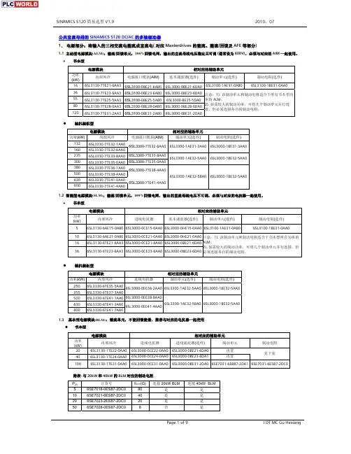
带中央定位双联电位器RK09L122002M选型规格书
- 格式:pdf
- 大小:543.14 KB
- 文档页数:4
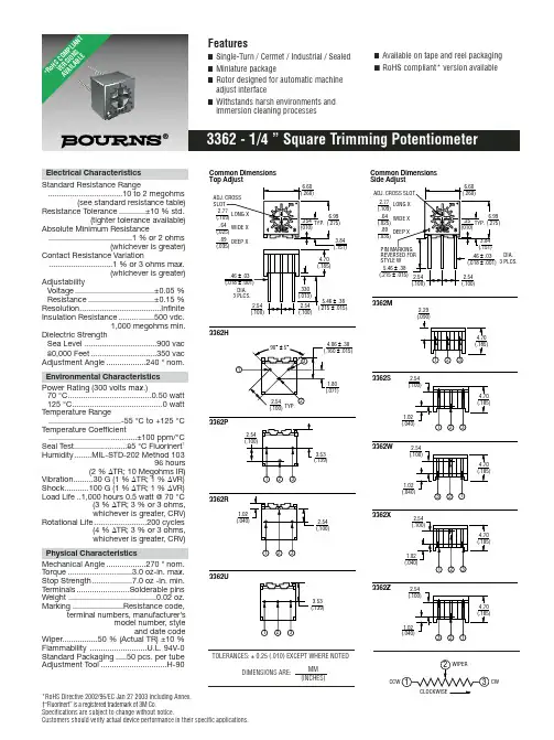
*RoHS Directive 2002/95/EC Jan 27 2003 including Annex.†“Fluorinert” is a registered trademark of 3M Co.Specifications are subject to change without notice.Customers should verify actual device performance in their specific applications.Electrical Characteristics Standard Resistance Range..................................10 to 2 megohms(see standard resistance table)Resistance Tolerance............±10 % std.(tighter tolerance available)Absolute Minimum Resistance......................................1 % or 2 ohms(whichever is greater)Contact Resistance Variation.............................1 % or 3 ohms max.(whichever is greater)AdjustabilityVoltage....................................±0.05 %Resistance..............................±0.15 %Resolution.....................................Infinite Insulation Resistance................500 vdc.1,000 megohms min.Dielectric StrengthSea Level .................................900 vac 80,000 Feet..............................350 vac Adjustment Angle..................240 °nom.Environmental Characteristics Power Rating (300 volts max.)70 °C......................................0.50 watt 125 °C.........................................0 watt Temperature Range.................................-55 °C to +125 °C Temperature Coefficient........................................±100 ppm/°C Seal Test........................85 °C Fluorinert †-STD-202 Method 10396 hours(2 % ∆TR; 10 Megohms IR)Vibration.........30 G (1 % ∆TR; 1 % ∆VR)Shock...........100 G (1 % ∆TR; 1 % ∆VR)Load Life ..1,000 hours 0.5 watt @ 70 °C(3 % ∆TR; 3 % or 3 ohms,whichever is greater, CRV)Rotational Life........................200 cycles(4 % ∆TR; 3 % or 3 ohms,whichever is greater, CRV)Physical CharacteristicsMechanical Angle..................270 °nom.Torque .............................3.0 oz-in. max.Stop Strength..................7.0 oz -in. min.Terminals........................Solderable pins Weight ........................................0.02 oz.Marking .......................Resistance code,terminal numbers, manufacturer’smodel number, styleand date codeWiper................50 % (Actual TR) ±10 %Flammability ..........................U.L. 94V-0Standard Packaging.....50 pcs. per tube Adjustment Tool..............................H-902.293362H3362M3362ZDIA.3362CLOCKWISEDIMENSIONS ARE:MM (INCHES)TOLERANCES: ±0.25 (.010) EXCEPT WHERE NOTED*Ro H S C O M P L I A N T V E R S I O N S A V A I L A B L ESpecifications are subject to change without notice.Customers should verify actual device performance in their specific applications.Resistance Resistance (Ohms)Code 1010020200505001001012002015005011,0001022,0002025,00050210,00010320,00020325,00025350,000503100,000104200,000204250,000254500,0005041,000,0001052,000,000205Standard Resistance TablePopular distribution resistance values listed in boldface. Special resistances available.REV. 04/06How to Order3362 P - 1 - 502 T __ LFModel StyleStandard or Modified Product Indicator-1 = Standard Product Resistance Code Optional Suffix LetterT =Knob*Packaging DesignatorBlank =Tube (Standard)R =Tape and Reel(M, U and P Pin Styles Only)A =Ammo Pack(M, U and P Pin Styles Only)TerminationsLF =100 % Tin-plated (RoHS compliant)Blank =90 % Tin / 10 % Lead-plated(Standard)*Knob option is available only in standard Tube packaging for terminal styles H, P , R and U.Consult factory for other available options.Packaging Specifications ALL PINS IN-LINE ON CENTERDIMENSIONS:1000/REEL/BOX2.54(.100) MM(INCHES) TOP ADJUST3362U-1, 3362P-1SIDE VIEW 3362U-1SIDE VIEW 3362P-1ALL PINS IN-LINE ON CENTERDIMENSIONS:750/REEL 1000/BOX2.54(.100) MM(INCHES) Meets EIA Specification 468.Top adjust models 3362H, P , R and U are available with a knob for finger adjustment.Add suffix letter “T” to order code.DIMENSIONS: MM/(INCHES)TOLERANCES: ±.25/(±.010) EXCEPT WHERE NOTEDProduct Dimensions。
电-气阀门定位器YT-1000系列使 用 说 明 书YTC Ver 1.02电-气阀门定位器 YT-1000系列说明书概要2安全注意事项2使用注意事项2质保期限2产品简介3标牌内容3特点4选型代码4主要参数5结构图6动作原理7外形尺寸8YT-1000L的外形尺寸图8 YT-1000R的外形尺寸图9安装10注意事项10安装时必要的工具10 YT-1000L的安装10利用支架安装YT-1000L11 YT-1000R的安装14利用支架安装YT-1000R15配管18注意事项18空压条件18配管条件18执行机构和气管的连接19电源连接-耐压防爆型 21耐压防爆型电线管的连接21耐压封闭型电缆的连接21接线端子连接22电源连接-本质安全型 22接线端子的连接22调节23零点调节23量程调节23自动/手动开关(旁路开关)24底座调节24节流孔调节25产品维护和检查25故障诊断和措施26目 录说明书概要z请充分阅读此说明书后,进行产品的安装,调试和使用。
z此说明书的内容未经事先通知的情况下可变。
z此说明书的内容未经我公司同意不得任意更改或替换。
z在此说明书未经说明的事项中出现的问题,请跟我公司或代理商联系。
z此说明书指定的参数适用于指定的型号和使用条件,有可能不能满足特殊的条件。
z为了产品的性能改进或升级,产品的参数,结构,部件等发生变动时,有可能没有反映到此说明书。
安全注意事项z为了安装人员,产品,系统的安全,安装本产品时请务必遵守本说明书注明的安全事项。
如果不正确遵守本说明书的安全事项,我公司不能保证其安全。
z因用户任意进行改造或维修本产品而发生的人身伤害或物质损失,我公司不给予赔偿。
需要维修或改造本产品时,请事先跟我公司联系。
z本产品是控制阀附件。
操作或运行时必须熟记相应控制阀的使用说明。
使用注意事项z搬运,安装或使用中,对产品过大的震动或撞击会成为产品故障的原因。
z超过规定参数范围使用也会成为产品故障的原因。
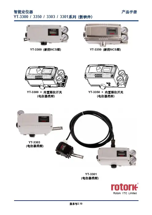
智能定位器产品手册YT-3300 / 3350 / 3303 / 3301系列(新软件)YT-3300 (新的NCS型)YT-3350 (新的NCS型)YT-3300 + 内置限位开关YT-3350 + 内置限位开关(电位器类型)(电位器类型)YT-3303YT-3303(电位器类型)YT-3301(电位器类型)Rotork YTC Limited目录1引言 (6)1.1一般用户信息 (6)1.2制造商保修 (6)1.3防爆警告(仅适用于本质安全型定位器) (7)2产品说明 (8)2.1常规信息 (8)2.2主要特点和功能 (8)2.3标签说明 (9)2.4产品代号 (15)YT-3300 / 3350 系列遵循以下后缀符号规则。
(15)YT-3303 系列遵循以下后缀符号规则。
(16)YT-3301 系列遵循以下后缀符号规则。
(17)2.5产品规格 (19)YT-3300 / 3303 / 3350规格 (19)YT-3301规格 (20)2.6证书 (22)2.7部件和组件 (26)YT-3300 / 3350 (26)YT-3303 (27)YT-3301 (28)2.8产品尺寸 (29)YT-3300 (29)YT-3350 (30)YT-3303 (31)YT-3301 (32)3安装 (33)3.1安全 (33)3.2安装工具 (33)3.3直行程定位器安装 (34)标准反馈杆型直行程定位器安装 (34)YT-3300L / 3350L适配器杆型的安装(无导管执行器) (40)3.4角行程定位器安装 (43)YT-3300R / 3350R组件 (43)YT-3303R组件 (44)YT-3301R远程传感器组件 (44)角行程支架信息(仅YT-3300R / 3350R / 3303R) (45)角行程定位器安装步骤 (46)4连接- 空气 (49)4.1安全 (49)4.2供给压力条件 (49)4.3管路连接 (49)4.4连接- 执行器管路 (50)单作用执行器 (50)双作用执行器 (51)5连接- 电源 (52)5.1安全 (52)5.2连接 (53)标准端子 (53)带微型限位开关选件的端子 (54)带感应式接近式限位开关选件的端子 (55)5.3接地 (56)6调节 (57)6.1限位开关调节 (57)6.2A/M开关调节 (58)6.3孔口件安装 (59)板型孔口件安装(YT-3303除外) (59)可变孔口件调节(仅YT-3303) (59)7选配型副PCB安装 (60)7.1安装步骤 (60)8维护 (62)8.1供给压力 (62)8.2密封件 (62)9自动校准和PCB操作 (63)9.1警告 (63)9.2LCD显示器和按钮 (63)LCD显示器和符号 (63)按钮和功能 (64)9.3菜单层级 (65)9.4运行模式监控 (66)9.5配置和操作 (67)9.6校准(CALIb) (71)动作类型(SINGLE / dOUBLE) (72)自动校准1(AUTO 1) (72)自动校准2(AUTO 2) (73)自动校准3(AUTO 3) (74)行程零点(TVL ZERO)和行程终点(TVL ENd) (75)9.7手动操作(MAN OPER) (76)通过设置位置进行手动操作(MAN SP) (76)利用MV进行手动操作(MAN MV) (76)9.8控制参数(CTL PARM) (77)死区(dEAdbANd) (77)向前P参数(KP UP)和向后P参数(KP dN) (78)向前积分时间参数(TI UP)和反向积分时间参数(TI dN) (78)向前D参数(Kd UP)和向后D参数(Kd dN) (79)GAP参数(GAP) (79)GAP P参数(GP) (80)GAP I参数(GI) (80)GAP D parameter (Gd) (80)自动死区模式(AUTO db) (81)性能模式(PER STbL / NORM / FAST) (81)9.9输入配置(IN CFG) (82)信号方向(SIG NORM / REVS) (82)分程模式(SPLIT 4.20 / 4.12 / 12.20 / CSt) (83)自定义分程模式零点(CST ZERO) (83)自定义分程模式终点(CST ENd) (84)阀门流量特性曲线(CHAR LIN / EQ / USER 5P / USER 21P) (84)用户设置5个特性点(USER 5P) (85)用户设置21个特性点(USER 21P) (86)用力打开(TSHUT OP) (87)用力关闭(TSHUT CL) (88)目标位置上升速率(RAMP UP)和目标位置下降速率(RAMP dN) (89)9.10输出配置(OUT CFG) (91)位置发送器方向(PTM NORM / REVS) (91)位置发送器零点/终点(PTM ZERO / ENd) (92)HART反馈方向(HT NORM / REVS) (93)反算(bACKCAL oFF / on) (94)9.11设备配置(dEV CFG) (95)动作设置(ACT) (95)直行程反馈杆设置模式(LEVT STd / AdT) (95)直行程差值(ITP oFF / on) (96)参数锁定(Write Protect,W UNLOCK / LOCK) (96)实际位置查看模式(View Mode,VI NORM / REVS) (96)轮询地址设置(POL AddR) (97)出厂重置(dEFAULT oFF / on) (97)定位器自测试(SELFTEST) (98)9.12诊断模式(dIAGNd) (99)默认警报设置 (100)程序状态(PS) (101)设备状态(dS) (102)查看监控计数(VI CNTS) (103)诊断限值配置(LIMT CFG) (104)重置警报状态(RST ALRM OFF / on) (105)查看事件日志(EVT LOG) (106)局部行程测试记录(查看PST结果记录,PST RSLT) (107)PST配置(PST CFG) (108)运行PST(PST NOW) (109)定期PST测试(PST计划,PST SCHd oFF / on) (109)9.13位置信息(INFO) (110)9.14自动校准过程中显示的错误代码 (112)9.15状态和警报代号 (113)10主要软件地图 (115)1 引言1.1 一般用户信息感谢您购买Rotork YTC Limited产品。
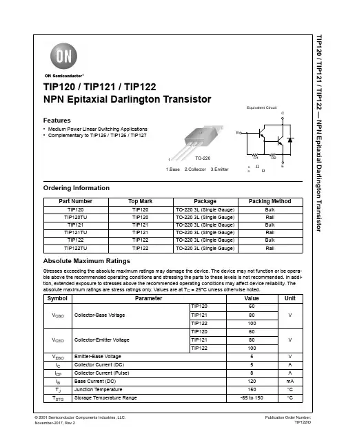
TIP120 / TIP121 / TIP122 — NPN Epitaxial Darlington TransistorTIP120 / TIP121 / TIP122NPN Epitaxial Darlington TransistorFeatures•Medium Power Linear Switching Applications •Complementary to TIP125 / TIP126 / TIP127Ordering InformationAbsolute Maximum RatingsStresses exceeding the absolute maximum ratings may damage the device. The device may not function or be opera-ble above the recommended operating conditions and stressing the parts to these levels is not recommended. In addi-tion, extended exposure to stresses above the recommended operating conditions may affect device reliability. The absolute maximum ratings are stress ratings only. Values are at T C = 25°C unless otherwise noted.Part NumberTop MarkPackagePacking MethodTIP120TIP120TO-220 3L (Single Gauge)Bulk TIP120TU TIP120TO-220 3L (Single Gauge)Rail TIP121TIP121TO-220 3L (Single Gauge)Bulk TIP121TU TIP121TO-220 3L (Single Gauge)Rail TIP122TIP122TO-220 3L (Single Gauge)Bulk TIP122TUTIP122TO-220 3L (Single Gauge)RailSymbolParameterValueUnitV CBOCollector-Base VoltageTIP12060VTIP12180TIP122100 V CEO Collector-Emitter Voltage TIP12060V TIP12180TIP122100 V EBO Emitter-Base Voltage 5V I C Collector Current (DC)5A I CP Collector Current (Pulse)8A I B Base Current (DC)120mA T J Junction Temperature 150°C T STGStorage Temperature Range-65 to 150°C1.Base2.Collector3.Emitter1TO-220Equivalent CircuitBECR1R2Ω≅ Ω≅Note:1.Pulse test: pw ≤ 300 μs, duty cycle ≤ 2%.V CE (sat) Collector-Emitter Saturation Voltage V I C = 5 A, I B = 20 mA 4.0 V BE (on) Base-Emitter On Voltage (1) V CE = 3 V, I C = 3 A 2.5V C obOutput CapacitanceV CB = 10 V, I E = 0, f = 0.1 MHz200pFON Semiconductor and are trademarks of Semiconductor Components Industries, LLC dba ON Semiconductor or its subsidiaries in the United States and/or other countries.ON Semiconductor owns the rights to a number of patents, trademarks, copyrights, trade secrets, and other intellectual property. A listing of ON Semiconductor’s product/patent coverage may be accessed atON Semiconductor makes no warranty, representation or guarantee regarding the suitability of its products for any particular purpose, nor does ON Semiconductor assume any liability arising out of the application or use of any product or circuit, and specifically disclaims any and all liability, including without limitation special, consequential or incidental damages.PUBLICATION ORDERING INFORMATION。
双模导航定位模块TAU1102数据手册V1.4免责声明本文档提供有关深圳华大北斗科技有限公司(以下简称“华大北斗”)的产品信息,以支持客户使用华大北斗产品进行产品设计开发与产品应用。
在使用本文档前,请您务必仔细阅读并透彻理解本声明。
您使用本文档的行为将被视为对本声明全部内容的认可和接受。
在法律允许的范围内,华大北斗对本文档所包含的信息、软件、产品和服务不提供任何相关陈述、担保和承诺。
所有此类信息、软件、产品和服务均按“原样”提供,并未附加任何类型的陈述、担保或承诺,包括对于产品适销性、特定用途适用性、所有权和不侵权的所有默示担保和承诺。
华大北斗将在任何情况下,都不对用户或者任何人士承担任何间接的、偶然的、附带的、特殊的、后果性(其中包括其他收入或利润损失)、惩罚性的或惩戒性的损害赔偿责任或受公平或禁令救济(无论是基于违反合同、侵权、疏忽、严格责任或其他)所产生的任何责任或索赔。
本文档及其包含的所有内容为华大北斗所有,受中国法律及适用的国际公约中有关著作权法律的保护。
未经明确的书面授权,任何人不得以任何形式复制、转载、改动、散布或以其它方式使用本文档部分或全部内容,违者将被依法追究责任。
华大北斗拥有随时修改本文档的权利,本文档内容如有更改,恕不另行通知。
更多产品信息与文档更新,请访问。
版权所有©深圳华大北斗科技有限公司,2021年。
保留所有权利。
目录1产品概述 (7)1.1产品简介 (7)1.2产品特性 (7)1.3产品图片 (7)1.4系统框图 (8)1.5性能指标 (8)2模块引脚定义 (10)3电气特性 (12)3.1极限条件 (12)3.2IO端口特性 (12)3.2.1PRRSTX、PRTRG端口特性 (12)3.2.2USB端口特性 (12)3.2.3其他IO端口特性 (13)3.3直流特性 (13)3.3.1工作条件 (13)3.3.2功耗 (13)4功能描述 (14)4.1电源 (14)4.2天线 (14)4.3复位与工作模式控制 (14)4.4串口通讯 (15)5机械规格 (16)6参考设计 (17)6.1原理图参考设计 (17)6.1.1TAU1102-1216A00 (17)6.1.2TAU1102-1216B00 (18)6.2PCB封装参考 (19)6.3LAYOUT注意事项 (19)7软件接口 (20)7.1NMEA消息格式 (20)7.1.1GGA - Global Positioning System Fix Data (20)7.1.2GLL-Geographic Position – Latitude/Longitude (21)7.1.3GSA-GNSS DOP and Active Satellites (21)7.1.4GSV-GNSS Satellites in View (22)7.1.5RMC-Recommended Minimum Specific GNSS Data (23)7.1.6VTG-Course over Ground and Ground Speed (23)7.1.7ZDA-Time & Date (24)7.1.8GST- GNSS Pseudorange Error Statistics (24)7.1.9TXT-ANT & USR message (25)7.2专属二进制消息 (25)7.3模式配置 (26)7.3.1CFG-SIMPLERST (26)8包装与处理 (27)8.1包装须知 (27)8.2包装 (27)8.2.1模块包装 (27)8.2.2运输包装 (28)8.3存储 (28)8.4ESD处理 (29)8.4.1ESD注意事项 (29)8.4.2ESD防护措施 (29)8.4.3湿敏等级 (29)9文档版本修订记录 (30)图目录图1 TAU1102产品图 (7)图2 TAU1102系统框图 (8)图3 引脚定义图 (10)图4 工作模式切换 (15)图5 最短复位时长 (15)图6模块机械尺寸图 (16)图7 TAU1102-1216A00参考设计 (17)图8 TAU1102-1216B00参考设计 (18)图9 TAU1102封装参考 (19)图11卷盘 (28)表目录表格1 TAU102-1216A00和TAU1102-1216B00差异 (7)表格2 性能指标 (8)表格3 引脚定义说明 (11)表格4 极限条件 (12)表格5 PRRSTX、PRTRG端口特性 (12)表格6 USB端口特性 (12)表格7 其他IO端口特性 (13)表格8 工作条件 (13)表格9 功耗 (13)表格10 天线状态NMEA输出 (14)表格11最短复位时长 (15)表格12尺寸 (16)表格13 NMEA 输出消息 (20)表格14 GGA 数据格式 (20)表格15 Position Fix Indicators (21)表格16 GLL Data Format (21)表格17 GSA Data Format (21)表格18 Mode 1 (22)表格19 Mode 2 (22)表格21 RMC Data Format (23)表格22 VTG Data Format (24)表格23 ZDA Data Format (24)表格24 GST Data Format (24)表格25 TXT Data Format (25)表格26 TAU1102专有命令集 (25)表格27 包装结构 (27)表格28 包装规格汇总 (28)1产品概述1.1产品简介TAU1102是一款低成本、高性价比的双模定位模块,搭载了华大北斗的CYNOSURE II GNSS SoC 芯片,支持接收BDS B1、GPS L1等卫星信号。

0198441113771, V 1.00, 09.2009LXM32M交流伺服驱动装置产品手册V1.00, 09.2009重要说明LXM32M 重要说明本手册属于产品的一部分。
请仔细阅读本手册,并遵照其中的说明。
请保管好本手册。
请务必向每位产品用户提供本手册及所有与产品有关的文件。
请仔细阅读并注意所有安全提示及"开始之前 — 安全信息"一章。
并非所有产品在所有国家或地区都有供应。
有关产品的供应状况,请查阅最新的产品目录。
保留如有技术内容修改而不另行通知的权利。
所有说明均为供参考的技术参数,并非所许诺的产品特性。
大多数未带有任何专用商标的产品名称也应视为其各自所有者的商标。
92.9,.1V,1773111448910 2交流伺服驱动装置0198441113771, V 1.00, 09.2009LXM32M 目录交流伺服驱动装置3目录重要说明. . . . . . . . . . . . . . . . . . . . . . . . .2目录. . . . . . . . . . . . . . . . . . . . . . . . . . .3关于本手册. . . . . . . . . . . . . . . . . . . . . . . .9其它参考文献. . . . . . . . . . . . . . . . . . . . . . 101序言. . . . . . . . . . . . . . . . . . . . . . . . . . . . . . . . . . . . . . . . . . . . . . . 111.1设备概述. . . . . . . . . . . . . . . . . . . . 111.2组件与接口. . . . . . . . . . . . . . . . . . . 121.3型号代码. . . . . . . . . . . . . . . . . . . . 132开始之前 - 安全信息 . . . . . . . . . . . . . . . . . . . . . . . . . . . . . . . . . 152.1操作人员资质. . . . . . . . . . . . . . . . . . 152.2指定用途. . . . . . . . . . . . . . . . . . . . 152.3危险等级. . . . . . . . . . . . . . . . . . . . 162.4基本信息. . . . . . . . . . . . . . . . . . . . 172.5DC 总线电压测量 . . . . . . . . . . . . . . . . 182.6安全功能. . . . . . . . . . . . . . . . . . . . 182.7标准和术语. . . . . . . . . . . . . . . . . . . 193技术参数 . . . . . . . . . . . . . . . . . . . . . . . . . . . . . . . . . . . . . . . . . . . 213.1环境条件. . . . . . . . . . . . . . . . . . . . 213.2机械参数. . . . . . . . . . . . . . . . . . . . 233.2.1尺寸图. . . . . . . . . . . . . . . . . . . . 233.3电气参数. . . . . . . . . . . . . . . . . . . . 253.3.1输出级. . . . . . . . . . . . . . . . . . . . 253.3.224VDC 控制系统电源. . . . . . . . . . . . . . 313.3.3信号. . . . . . . . . . . . . . . . . . . . . 323.3.4安全功能. . . . . . . . . . . . . . . . . . . 393.3.5制动电阻. . . . . . . . . . . . . . . . . . . 403.3.6内部电源滤波器. . . . . . . . . . . . . . . . 423.3.7电源滤波器 (配件) . . . . . . . . . . . . . 433.3.8电源扼流圈(配件). . . . . . . . . . . . . .443.4要求:UL 508C . . . . . . . . . . . . . . . . . 453.5认证. . . . . . . . . . . . . . . . . . . . . . 453.6一致性声明. . . . . . . . . . . . . . . . . . . 464交流伺服驱动装置目录LXM32M0198441113771, V 1.00, 09.20093.7功能安全性认证证书. . . . . . . . . . . . . . . 474基础知识. . . . . . . . . . . . . . . . . . . . . . . . . . . . . . . . . . . . . . . . . . . .494.1安全功能. . . . . . . . . . . . . . . . . . . . 495设计 . . . . . . . . . . . . . . . . . . . . . . . . . . . . . . . . . . . . . . . . . . . . . . .515.1电磁兼容性(EMC). . . . . . . . . . . . . . . . 525.2电缆. . . . . . . . . . . . . . . . . . . . . . 555.2.1所需电缆一览表 . . . . . . . . . . . . . . . 565.3剩余电流动作保护器. . . . . . . . . . . . . . . 575.4在 IT 网络中使用. . . . . . . . . . . . . . . . 575.5DC 总线并联连接 . . . . . . . . . . . . . . . . 585.6电源扼流圈. . . . . . . . . . . . . . . . . . . 595.7电源滤波器. . . . . . . . . . . . . . . . . . . 605.7.1关闭 Y 电容器. . . . . . . . . . . . . . . . 615.8确定制动电阻参数. . . . . . . . . . . . . . . . 625.8.1内部制动电阻 . . . . . . . . . . . . . . . . 625.8.2外接制动电阻 . . . . . . . . . . . . . . . . 635.8.3参数选择帮助 . . . . . . . . . . . . . . . . 635.9STO 安全功能 ("Safe Torque Off"). . . . . . . . 675.9.1定义 . . . . . . . . . . . . . . . . . . . . 675.9.2功能 . . . . . . . . . . . . . . . . . . . . 675.9.3关于使用安全功能的要求 . . . . . . . . . . . 675.9.4STO 应用示例 . . . . . . . . . . . . . . . . 695.10逻辑类型. . . . . . . . . . . . . . . . . . . . 705.11监控功能. . . . . . . . . . . . . . . . . . . . 715.12可配置的输入和输出. . . . . . . . . . . . . . . 716安装 . . . . . . . . . . . . . . . . . . . . . . . . . . . . . . . . . . . . . . . . . . . . . . .736.1机械安装. . . . . . . . . . . . . . . . . . . . 736.1.1设备装配 . . . . . . . . . . . . . . . . . . 746.1.2安装电源滤波器、电源扼流圈和制动电阻 . . . . 766.2电气安装. . . . . . . . . . . . . . . . . . . . 786.2.1安装程序概况 . . . . . . . . . . . . . . . . 796.2.2连接概况 . . . . . . . . . . . . . . . . . . 806.2.3连接接地螺钉 . . . . . . . . . . . . . . . . 816.2.4电机相位连接(CN10,电机) . . . . . . . . . 816.2.5止动闸连接(CN11,闸) . . . . . . . . . . . 856.2.6DC 总线连接(CN9,DC 总线). . . . . . . . . 866.2.7制动电阻连接(CN8,Braking Resistor). . . . 876.2.8连接输出级电源 (CN1) . . . . . . . . . . . . 896.2.9电机编码器连接 (CN3) . . . . . . . . . . . . 936.2.10PTO 连接(CN4,连续脉冲输出) . . . . . . . . 956.2.11PTI 连接(CN5,连续脉冲输入) . . . . . . . . 966.2.12连接控制系统电源和 STO (CN2、DC 电源和 STO) 1006.2.13数字输入/输出 (CN6) 端口. . . . . . . . . . 1020198441113771, V 1.00, 09.2009LXM32M目录交流伺服驱动装置56.2.14连接装有调试软件的 PC (CN7) . . . . . . . . 1046.2.15安装和移除插件(Slot 1、Slot 2、Slot 3). . 1066.3检查安装情况. . . . . . . . . . . . . . . . . 1087调试. . . . . . . . . . . . . . . . . . . . . . . . . . . . . . . . . . . . . . . . . . . . . . 1097.1基本信息. . . . . . . . . . . . . . . . . . . 1097.2概述. . . . . . . . . . . . . . . . . . . . . 1117.2.1调试步骤. . . . . . . . . . . . . . . . . . 1117.2.2调试工具. . . . . . . . . . . . . . . . . . 1117.3集成的 HMI . . . . . . . . . . . . . . . . . . 1127.3.1显示和操作. . . . . . . . . . . . . . . . . 1137.3.2菜单结构. . . . . . . . . . . . . . . . . . 1147.3.3进行设置. . . . . . . . . . . . . . . . . . 1157.4调试软件. . . . . . . . . . . . . . . . . . . 1167.5调试步骤. . . . . . . . . . . . . . . . . . . 1177.5.1"首次设置" . . . . . . . . . . . . . . . . 1177.5.2运行状态(状态图). . . . . . . . . . . . . 1187.5.3设置主要参数和极限值. . . . . . . . . . . . 1197.5.4数字输入/输出. . . . . . . . . . . . . . . 1227.5.5限位开关信号检测. . . . . . . . . . . . . . 1247.5.6测试 STO 安全功能 . . . . . . . . . . . . . 1257.5.7止动闸. . . . . . . . . . . . . . . . . . . 1267.5.8转动方向检查. . . . . . . . . . . . . . . . 1287.5.9编码器参数值设置. . . . . . . . . . . . . . 1297.5.10设置制动电阻的参数. . . . . . . . . . . . . 1327.5.11执行自动调整. . . . . . . . . . . . . . . . 1347.5.12自动调整功能的高级设置. . . . . . . . . . . 1367.6利用阶跃响应优化控制器. . . . . . . . . . . . 1387.6.1控制器结构. . . . . . . . . . . . . . . . . 1387.6.2优化. . . . . . . . . . . . . . . . . . . . 1397.6.3优化转速控制器. . . . . . . . . . . . . . . 1407.6.4检查及优化默认设置. . . . . . . . . . . . . 1447.6.5优化位置控制器. . . . . . . . . . . . . . .1457.7存储卡 (Memory-Card). . . . . . . . . . . . . 1477.7.1用存储卡进行数据交换. . . . . . . . . . . . 1497.8复制当前设备设置. . . . . . . . . . . . . . . 1508运行. . . . . . . . . . . . . . . . . . . . . . . . . . . . . . . . . . . . . . . . . . . . . . 1518.1访问通道. . . . . . . . . . . . . . . . . . . 1528.2运行状态. . . . . . . . . . . . . . . . . . . 1548.2.1状态图. . . . . . . . . . . . . . . . . . . 1548.2.2状态转变. . . . . . . . . . . . . . . . . . 1568.2.3显示运行状态. . . . . . . . . . . . . . . . 1578.2.4转变运行状态. . . . . . . . . . . . . . . .1588.3运行模式. . . . . . . . . . . . . . . . . . . 1598.3.1启动和转换运行模式. . . . . . . . . . . . . 1598.3.2运行模式 Jog. . . . . . . . . . . . . . . . 1596交流伺服驱动装置目录LXM32M0198441113771, V 1.00, 09.20098.3.3运行模式Electronic Gear. . . . . . . . . . . 1638.3.4运行模式 Profile Torque . . . . . . . . . . . 1708.3.5运行模式Profile Velocity . . . . . . . . . . 1728.3.6运行模式 Profile Position . . . . . . . . . . 1748.3.7运行模式基准点定位 . . . . . . . . . . . . . 1778.4功能. . . . . . . . . . . . . . . . . . . . . . 1888.4.1运动方向的配置 . . . . . . . . . . . . . . . 1888.4.2PTO 接口的配置 . . . . . . . . . . . . . . . 1898.4.3比例配置 . . . . . . . . . . . . . . . . . . 1908.4.4数字信号输入和输出的配置 . . . . . . . . . . 1948.4.5比例的配置 . . . . . . . . . . . . . . . . . 2068.4.6设备内部信号监控的功能 . . . . . . . . . . . 2218.4.7目标值处理功能 . . . . . . . . . . . . . . . 2308.4.8运动监控的功能 . . . . . . . . . . . . . . . 2409示例 . . . . . . . . . . . . . . . . . . . . . . . . . . . . . . . . . . . . . . . . . . . . . .2599.1一般提示. . . . . . . . . . . . . . . . . . . . 2599.2使用插件进行操作的示例. . . . . . . . . . . . . 26010诊断与排除故障 . . . . . . . . . . . . . . . . . . . . . . . . . . . . . . . . . . . . .26110.1状态查询/状态显示. . . . . . . . . . . . . . . 26110.1.1通过集成的HMI 诊断 . . . . . . . . . . . . . 26210.1.2通过调试软件诊断 . . . . . . . . . . . . . . 26310.1.3通过现场总线诊断 . . . . . . . . . . . . . . 26310.1.4现场总线状态LED. . . . . . . . . . . . . . . 26310.2故障存储器. . . . . . . . . . . . . . . . . . . 26410.2.1通过现场总线读取故障存储器 . . . . . . . . . 26410.2.2通过调试软件读取故障存储器 . . . . . . . . . 26610.3集成的HMI 上的特别菜单. . . . . . . . . . . . . 26710.3.1读取和确认警告 . . . . . . . . . . . . . . . 26710.3.2读取和确认故障 . . . . . . . . . . . . . . . 26810.3.3确认插件插槽上的变更 . . . . . . . . . . . . 26910.3.4确认电机的更换 . . . . . . . . . . . . . . . 27010.4诊断与故障查找. . . . . . . . . . . . . . . . . 27010.4.1按照故障位分类的警告和故障 . . . . . . . . . 27010.4.2警告和故障表 . . . . . . . . . . . . . . . . 27311参数 . . . . . . . . . . . . . . . . . . . . . . . . . . . . . . . . . . . . . . . . . . . . . .28711.1参数显示. . . . . . . . . . . . . . . . . . . . 28711.1.1现场总线的小数处理 . . . . . . . . . . . . . 28811.2参数列表. . . . . . . . . . . . . . . . . . . . 28912附件与备件 . . . . . . . . . . . . . . . . . . . . . . . . . . . . . . . . . . . . . . . . .36712.1调试工具. . . . . . . . . . . . . . . . . . . . 36712.2存储卡. . . . . . . . . . . . . . . . . . . . . 36712.3其他模块. . . . . . . . . . . . . . . . . . . . 36712.4应用铭牌. . . . . . . . . . . . . . . . . . . . 3670198441113771, V 1.00, 09.2009LXM32M目录交流伺服驱动装置712.5带插头的 CANopen 电缆 . . . . . . . . . . . . 36712.6CANopen 插头、分配器、终端电阻. . . . . . . . 36812.7CANopen 电缆. . . . . . . . . . . . . . . . . 36812.8适用于编码器信号 LXM05/LXM15 到 LXM32的适配器电缆. . . . . . . . . . . . . . . . . 36912.9PTO 和 PTI 电缆 . . . . . . . . . . . . . . . 36912.10电机电缆. . . . . . . . . . . . . . . . . . . 36912.10.1电机电缆,1.5mm2 . . . . . . . . . . . . . 36912.10.2电机电缆,2.5mm2 . . . . . . . . . . . . . 37012.10.3电机电缆,4mm2 . . . . . . . . . . . . . . 37012.11编码器电缆. . . . . . . . . . . . . . . . . . 37112.12插头. . . . . . . . . . . . . . . . . . . . . 37212.13外部制动电阻. . . . . . . . . . . . . . . . . 37212.14配件 DC 总线. . . . . . . . . . . . . . . . . 37312.15电源扼流圈. . . . . . . . . . . . . . . . . . 37312.16外部电源滤波器. . . . . . . . . . . . . . . . 37312.17备件、插头、风扇、盖板. . . . . . . . . . . . 37313售后服务、维护与废弃物处理. . . . . . . . . . . . . . . . . . . . . . . . . . 37513.1售后服务地址. . . . . . . . . . . . . . . . . 37513.2维护. . . . . . . . . . . . . . . . . . . . . 37513.2.1安全功能 STO 的使用寿命 . . . . . . . . . . 37513.3更换设备. . . . . . . . . . . . . . . . . . . 37613.4更换插件. . . . . . . . . . . . . . . . . . . 37713.5更换电机. . . . . . . . . . . . . . . . . . . 37813.6发运、仓储、废弃物处理. . . . . . . . . . . . 37914术语表. . . . . . . . . . . . . . . . . . . . . . . . . . . . . . . . . . . . . . . . . . . . 38114.1单位及其换算表. . . . . . . . . . . . . . . . 38114.1.1长度. . . . . . . . . . . . . . . . . . . . 38114.1.2质量. . . . . . . . . . . . . . . . . . . . 38114.1.3力. . . . . . . . . . . . . . . . . . . . . 38114.1.4功率. . . . . . . . . . . . . . . . . . . . 38114.1.5转动. . . . . . . . . . . . . . . . . . . . 38214.1.6转矩. . . . . . . . . . . . . . . . . . . . 38214.1.7转动惯量. . . . . . . . . . . . . . . . . . 38214.1.8温度. . . . . . . . . . . . . . . . . . . . 38214.1.9导线横截面. . . . . . . . . . . . . . . . .38214.2术语和缩写. . . . . . . . . . . . . . . . . . 383目录LXM32M92.9,.1V,1773111448910 8交流伺服驱动装置0198441113771, V 1.00, 09.2009LXM32M 关于本手册交流伺服驱动装置9关于本手册本手册适用于所有LXM32M 标准产品。
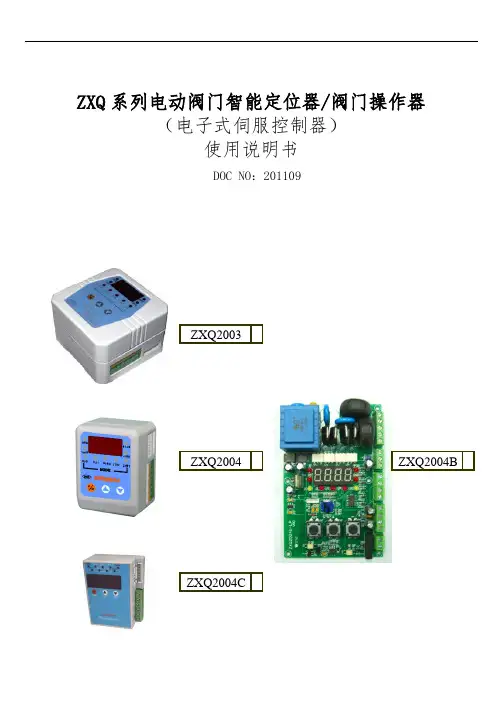
ZXQ系列电动阀门智能定位器/阀门操作器(电子式伺服控制器)使用说明书DOC NO:201109ZXQ2003ZXQ2004BZXQ2004ZXQ2004C目录一、概述 (2)二、主要技术指标 (2)三、定位器面板 (3)四、接线方式 (5)五、设定操作方法 (6)六、错误代码列表 (9)附录:其它标定操作(出厂后如需此项操作,请在厂家指导下使用) (9)如顾客所购买的是本公司Z型(机电一体)执行器,部定位器无需对执行器转角标定,接线无误即可正常使用。
ZXQ系列电动阀门智能定位器是以工业单片机为核心的智能信号采集控制系统,体积小巧,可选择安装在电动执行器的接线盒或以DIN导轨方式固定在外,能直接接收工业仪表或计算机等输出的4~20mA DC信号(其它输入信号类型可在出厂前定制),与电位器反馈的电动执行器配套对各种阀门或装置进行精确定位操作,能对电动执行器的转角(或位移)进行自由标定,同时输出4~20mA DC的执行器转角位置(或位移)反馈转换信号,可精确设定执行器转角位置的下限限位值和上限限位值,定位器采用3个按键操作,9个LED灯可直接显示定位器模态,4位数码LED通过按键切换显示阀位实际开度值、阀位设定开度值、定位器壳温度,操作方便。
●控制精度:0.1%~3.0%(通过U4参数可调)●可接电动执行器反馈信号:电位器500Ω~10KΩ●可接收外部控制信号(DC):4~20mA (1~5V、0~10V、开关量等出厂前定制)●输入阻抗:250Ω;●通过修改U1参数可设定:①DRTA/正动作,RVSA/逆动作模态②输入信号中断时“中断”模态—OPEN(开)、STOP(停)、SHUT(闭) ●可选:可控硅输出(AC,1000V,25A)●输出执行器位置信号:低漂移输出4~20mA DC对应执行器全闭至全开,信号完全与输入隔离(光电隔离),输出负载≤500Ω●环境温度:0~80℃,相对湿度:≤90%RH●有超温保护功能: 定位器壳温度≥70℃时,定位器停止对执行器的开闭控制●外形尺寸:ZXQ2003→77mm(底面长)×76mm(底面宽)×51mm(高/厚);ZXQ2004→74 mm(底面长)×57mm(底面宽)×45mm(高/厚)ZXQ2004B→119mm(底面长)×76mm(底面宽)×26mm(高/厚)ZXQ2004C→62mm(底面长)×48mm(底面宽)×26mm(高/厚)●可通过按键自由标定输入信号所对应执行器的动作区间(一般标定为电动执行器全闭、全开位置)●可设定最大阀位限制值与最小阀位限制值●密码锁,防止误操作●防执行器频繁启动功能●带故障报警代码指示功能(E-0X)●按输入信号和执行器转角位置进行智能步距调整精确定位■参照下图定位器接线端子和定位器外壳上的接线图连接好电动执行器和电源连线,注意连接时的极性,为减少电机干扰,应将电动执行器的电机控制线和反馈信号线分开走线;定位器的弱电信号线应尽量短些,若必须使用较长的连线时,应采用屏蔽信号线,外屏蔽与控制柜外壳妥善接地。
带带stk61说明书第一篇:产品概述STK61是一款高性能的嵌入式控制器,适用于各种电子设备和工业自动化应用。
该控制器集成了先进的处理器和多种接口,可以实现实时控制和数据处理。
该控制器具备可编程的功能,用户可以通过编程的方式实现自定义的功能和控制策略。
第二篇:技术规格- 处理器:32位ARM Cortex-M4-主频:72MHz- 存储器:256KB Flash,32KB RAM-通信接口:UART、I2C、SPI、CAN-数模转换器:12位ADC,8通道-脉宽调制:PWM输出,6通道-定时器:多个通用定时器-中断控制器:多级优先级中断-控制接口:GPIO,可编程IO接口-电源:3.3VDC,功耗低第三篇:外观和连接STK61控制器采用紧凑的设计,尺寸为80mm x 60mm。
控制器底部有一个标准的20针引脚接口,可以直接插入主板或者外围设备中。
接口分布合理,易于使用。
控制器上方有一个显示屏和若干按键,用于用户界面的操作。
第四篇:软件开发环境第五篇:控制器功能STK61控制器具备多种功能和特性,方便用户进行各种应用开发:- 高性能处理器:STK61集成了32位ARM Cortex-M4处理器,主频达到72MHz,可以处理复杂的算法和逻辑。
-多种通信接口:STK61支持UART、I2C、SPI、CAN等多种通信接口,方便用户与其他设备进行数据交换和通信。
-多种定时器:STK61提供多个通用定时器,可以用于实现各种时间控制。
-多级优先级中断:STK61的中断控制器支持多级优先级中断,可以实现实时响应和任务调度。
-可编程IO接口:STK61具备可编程IO接口,用户可以根据自己的需求进行灵活的IO控制。
-低功耗设计:STK61采用了低功耗设计,可以延长电池寿命,节约能源。
第六篇:应用领域STK61控制器适用于各种电子设备和工业自动化场景,包括但不限于以下应用领域:-家用电器控制:STK61可以用于家电产品的控制和交互,如电视、空调、冰箱等。
MT-1220 / MT-12253 1/2 Digital MultimeterUser’s Manual2nd Edition, 2020©2020 Copyright by Prokit’s Industries Co., Ltd.※General InformationThe meter is a multi-function instrument with high measurement accuracy, fast response, and high safety level. Embedded with a special IC up to2000 counts, this IC is composed of high-precision A/D converter withhigh-speed digital processor. It is with accurate measurement, highresolution, fast operation, complete software calibration, no change inlong-term use in accuracy, which is suitable for professional engineers,maintenance engineers, teaching, etc.Please read carefully this operation manual and pay attention to safetyguidelines before operating this meter.1.1 Safety Information1.1.1 Safety Instructions●Before operating this meter, the operator must observe all standardsafety procedures in the two respects below:A. Safety procedures against electric shockB. Safety procedures against unintended use●To ensure your personal safety, please use the test lead thataccompanies the meter. Before operating this meter, ensure that the test lead is flawless.1.1.2 Safety Considerations●When the meter is used in the vicinity of the equipment that producesstrong electromagnetic interferences, the reading on the meter will growunstable and even produce serious errors.●Don't operate the meter or pen-shaped meter whose appearance isdamaged.●The safety function of the meter will become null if the meter is notproperly operated.●The meter must be operated with great care when working in the vicinityof an exposed conductor or bus line.●The meter is prohibited from being used in the vicinity of any explosivegas, vapor or dust.●The measurement must be made with correct input terminals andfunctions and within the allowable measuring range.●T o prevent the meter from being damaged, the value to be input shall notexceed the extremes allowed by each measuring range.●When the meter has already been connected to the line being measured,the operator is prohibited from touching the input terminal that is not inservice.●When the voltage measured exceeds DC60V or AC30V (valid value),the operator shall be careful enough to avoid electric shock.●When making measurement with a test lead, place your fingers behindits protective ring.●When switching to another measuring range, be sure that test lead hasalready been taken off the measured circuit.●For all DC functions, to prevent potential electric shock as a result ofincorrect reading, please first use AC functions to check the absence of any AV voltage. Then, select DC voltage measuring range equivalent to or greater than that for AC voltage.●Before the tests on electric resistance, diode, continuity, the operatormust cut off the power supply to the circuit to be measured, anddischarge all high-voltage capacitors within the circuit to be measured.●The electric resistance measurement or continuity test cannot be carriedout in any live electrical circuit.●Before the current measurement, the operator must first examine theprotective tube of the meter. Before connecting the meter to the circuit to be measured, the operator must first power off the aforesaid circuit.●Before repairing TV sets or measuring power switching circuit, theoperator must be careful enough to prevent high amplitude voltageimpulse from damaging the meter.●This meter uses 3 x 1.5V AAA batteries that must be correctly installedinto the battery compartment.●When appears, the batteries must be replaced immediately. Thelow level of a battery will result in incorrect reading on the meter, which is likely to bring electric shock or personal injury to the operator.●In measurement, category II voltage shall not exceed 600V respectively.●The meter shall not be in service if its case (or part of its case) is dismantled.1.1.3 Safety Symbol:The safety symbols that appear on the meter's body and in this OperationEquipment with double insulation or reinforcedinsulation protectionAC (alternating current)DC (direct current)GroundCAT. II 600 VConform with European Union standard1.1.4 Maintenance Practices for Safety●The operator must first pull out the test lead when the meter's case isopened or the battery cover is dismantled.●The designated replacement parts must be used at the moment ofmaintenance.●The operator must cut off all relevant power supplies before opening themeter. At the same time, the operator must avoid damage to the meter's elements by ensure that he himself doesn't carry any static.●The meter can only be calibrated, repaired and maintained byprofessionals.●When the meter's case is opened, the operator must understand the factthat the presence of some capacitance may promise the dangerousvoltages even if the power supply to the meter is cut off.●The operator should stop using and maintain the meter immediately ifany abnormality has been observed on the meter. The operator mustsee to it that the meter cannot be in service unless it is provedconforming.●When the meter is left idle for a long period, the operator shall removethe battery and place it in a place free from high temperature andhumidity.1.2 Input Protection Measures●The meter can sustain the maximum input voltage of 600V (DC/AC) atthe moment of voltage measurement.●The limit voltage is 250 ACV or the equivalent RMS voltage when theresistance, continuity or diode is under measuring.●The protective tube (F200mA/250V) is used for protection purpose whenmA current measurements are carried out. The protective tube(F10A/250V) is used for protection purpose when A currentmeasurements are carried out.2. General Description 2.1 Schematic Diagram①. LED light②.Non-contact voltage indicator ③.LCD screen ④.Buzzer ⑤.Backlight & LED key ⑥. Rotary switch ⑦.Input socket ⑧. Data hold key ⑨.hFE socket 2.2 Symbols Description battery when the low battery symbol appears. Auto power off Negative input polarityInput voltage ACInput voltage DCDiode test or Continuity testData hold NCVNon-contact AC voltage detection ③ ① ② ④ ⑤ ⑥⑦⑧ ⑨2.5 Accessories1. Operation Manual X 1 pce2. Test lead X 1 pair3. Operational Guidelines3.1 Auto Power OffIf no operations are made in 15 minutes following the initialization, the meter will sound to remind the operator to automatically cut off power supply and enter the state of dormancy. The meter can be rebooted when the operator presses any key in the auto power off mode.3.2 Measurement guidelines3.2.1 AC Voltage and DC Voltage MeasurementThe meter provides DC voltage measuring ranges as follows: 200.0mV, 2.000V, 20.00V, 200.0V and 600V, and AC voltage measuring ranges:current.●Turn the rotary switch to the position ~V or V.●Connect the test lead in black and test lead in red to COM input socketand V input socket respectively.●Use another two ends of the test lead to measure the voltage of thecircuit to be measured. (In parallel connection with the circuit to bemeasured)●Read the measured voltage value on LCD screen. When DC voltagemeasurement is attempted, the display unit will show the voltage polarity of the circuit connected to the pen-shaped meter in red.3.2.2 Electric Resistance MeasurementOhm is the unit of electric resistance (Ω).The measuring ranges of electric resistance of this meter are 200.0Ω,●Connect the test lead in black and test lead in red to COM input socketand V/Ωinput socket respectively.●Use another two ends of the test lead to measure the electricresistance of the circuit to be measured.●Read the measured electric resistance value on LCD screen.Notes:●The measured value of the electric resistance of the circuit differs a bitfrom the rated value of the electric resistance.●To ensure measurement accuracy, in attempting a low resistancemeasurement, first put two pen-shaped meters in short circuit andcapture the resistance reading of these short circuits. Then subtractthe aforesaid reading from the measured resistance.●When the meter is in open circuit, the display unit will show "OL" thatindicates the measured value is over the measuring range.●Turn the rotary switch to the position .●Connect the test leads in black and in red to COM input socket andV/Ωinput socket respectively.●Connect the test leads in black and in red to the positive and negativepoles of the diode to be tested respectively.●The meter displays the forward bias value of the diode to be tested. Ifthe polarity of the test lead is reversed, the meter will display "OL".Steps for a continuity test:●Connect the test lead in black and test lead in red to COM input socketand V/Ωinput socket respectively.●Use another two ends of the test lead to measure the resistance of thecircuit to be measured. If the measured distance the beeper will sound continuously, and the LED will be on.●Check the transistor is NPN or PNP type, insert the emitter, base andcollector separately to the correct hole, the approximate value will bedisplayed on LCD.3.2.5 Current MeasurementThe meter provides DC current measuring ranges as follows: 2mA,●Connect the test lead in black to COM input socket. Connect the testlead in red to a mA input socket when the measured current is less than 200mA; connect the test lead in red to a 10A input socket when themeasured current is 200mA~10A.●Disconnection of the circuit to be measured Connect the test lead inblack to the end of disconnected circuit (the voltage is lower) andconnect the test lead in red to the end of the disconnected circuit(voltage is higher).●Connect the power to the circuit and capture the displayed reading. Ifthe display unit only shows "OL", it means the input is over theselected measuring range. At this moment, turn the rotary switch to a higher measuring range.3.2.6 Temperature Measurement●Turn the rotary switch to the appropriate position (℃).●Insert the cathode of thermocouple’s cold end to " COM" jack andanod e to " V/Ω" terminal, put the working end on or in the testedobject, temperature value can be read on LCD in Celsius.3.2.7 NCV Test (Non-contact Voltage Detection)Turn the rotary switch to NCV position, and place the top of the meter approach the conductor. If the meter detects the AC voltage, the indicators for signal density (high, medium and low) will be on in accordance with thedetected density, while the beeper will sounds alarms at differentfrequencies.Note:●Voltage may still remain in the absence of any indication. The operatorshall not rely on non-contact voltage detector to check the presence ofvoltage. The detection operation may be affected by various factors,including socket design, insulation thickness and type.●When the voltage is input into the meter's input terminal, the voltagesensor LED may be on as a result of induced voltage.●External sources of interference (like flashlight and motor) may triggernon-contact voltage detection.4. Technical Parameters4.1 Overall Parameters●Operating environment:600V CAT II, Pollution level: 2Altitude: < 2000 mWorking temperature & humidity: 0~40O C(The requirements will not be considered when temperature is less than 10℃and relative humidity is below 80%).Storage temperature & humidity: -10~60O C(Batteries shall be removed when RH is below 70%).●Coefficient of temperature: 0.1⨯accuracy/ O C (<18 O C or >28 O C).●Allowable max voltage between terminal to be measured and ground:600V DC or AC (valid value)●Protection of protective tube: mA position: protective tube F200mA/250V; A position protective tube F 10A/250V●Rotation rate: approximately 3 revolutions/second●Display unit: 2000 counts displayed on LCD screen. Automaticallydisplay the symbol for unit in accordance with measurement functionposition.●Outrange indication: the LCD screen will display "OL".●Battery Low indication: “” will appear when the battery's voltage isbelow the normal working voltage.●Input polarity indication: “-” will automatically appear.●Power: 3 x 1.5V AAA battery●Dimensions: 148mm(L)×79mm(W)×48mm(H).●Weight: Approximately 210g (not included batteries or test leads)4.2 Precision IndicatorAccuracy: ±(% reading + digit)The accuracy warranty will run for 1 year upon the ex-factory date. Reference conditions: Ambient temperature is between 18℃and 28℃and relative humidity is no more than 80%.Maximal input voltage: 600V DC or AC valid valueMaximal input voltage: 600V DC or AC valid valueFrequency response: 40Hz-400HzOpen-circuit voltage: 2.4VThe buzzer beeps when the resistance is less than30Overload protection: 250V DC/ACprotective tube for mA measuring range (F200mA/250V) ;protective tube for 10A measuring range (F10A/250V) .When the measured current is over 5A, the duration of continuousmeasurement shall not be over 10 seconds. The current measurement shall be carried out 1 minute after the completion of previous measurement.Overload protection: 250V DC/AC5. Meter MaintenanceThis section provides the basic information on maintenance, including the descriptions about replacement of protective tubes and batteries. Do not attempt the meter maintenance unless you are experienced in maintenance and have read the information on calibration, performance test andmaintenance.the meter's shell. Don't attempt the use of any abrading or chemical solvent. The dirty or damp input socket may affect reading.Steps for cleaning input sockets:● Disenable the meter and pull all test leads out of the input socket.● Clean up all dirty substances on sockets.● Use a new cotton ball with a detergent or lubricant to clean each socket, because lubricant can prevent the socket vulnerable to dampness from pollution.5.2 Battery & Fuse ReplacementTo avoid any electric shock or personal injury as a result ofincorrect reading, replace batteries once the symbol “”appear on the display unit.To avoid any electric shock or personal injury, don't attempt toopen the battery cover to replace batteries, unless you havealready powered off the device and carried out an examinationto ensure that the test lead has been disconnected from thecircuit to be measured.Battery Replacement:1. Turn off the power of the meter.2. Disconnect all test leads from the input socket.3. Use a screwdriver to remove the screw of battery cover.4. Take off the battery cover.5. Take out the old batteries carefully and replace with 3 pcs 1.5 V AAA newbatteries.6. Fix the battery cover.Fuse ReplacementWhen fuse is blown, replace with the same type of fuse.1. Turn off the power of the meter and take out the holster.2. Use a screwdriver to remove the screw of back cover.3. Take off the back cover.4. Remove the blown fuse and replace with the same type of fuse5. Screw the back cover6. Put the holster back.MT-1220/MT-1225 3 1/2數位電表使用說明書1.概述MT-12系列是測量精度高,回應速度快,安全可靠的多用數字儀錶,內嵌有2000計數的專用晶片,此晶片為高精度AD搭配高速數字處理器組成,具有測量準確,解析度高,運算速度快特點。
产品编号
RK09L122002M
电阻体数2联
安装⽅向Horizontal type
軸受固定⽅法螺纹固定
操作部形状平轴
操作部长度15mm
中央定位有
总阻值50kΩ
电阻规律1B
使⽤温度范围-10℃ to +70℃
电性能总阻值允许差±20%
额定功率0.05W
最⾼使⽤电压50V AC, 10V DC
剩余电阻50Ω max.
绝缘电阻100MΩ min. 250V DC
耐电压300V AC for 1 minute
机械性能全旋转⾓度300°±5°
旋转扭矩2 to 25mN·m
终端⽌挡强度0.5N·m
轴推拉强度80N max.
耐振性能10 to 55 to 10Hz/分, 全振幅1.5mm, X.Y.Z 3⽅向各2⼩时
耐久性能操作寿命15,000 cycles
最⼩订货单位(pcs.)⽇本1,000
9型⾦属轴铰接型 RK09L系列
出⼝2,000
照⽚
外形图
安装孔尺⼨图
⾃插⼊侧看
轴承与机架固定尺⼨
是附加到各产品上的零部件。
附加零部件
包装规格
托盘
包装数(pcs.)1箱/⽇本1,000
1箱/出⼝包装2,000
出⼝包装箱尺⼨(mm)364×473×176
焊接条件
浸焊⽅式的参考举例
预热焊接⾯表⾯温度100℃ max.
加热时间2 min. max.
浸焊焊接温度260±5℃ max.
焊接时间5±1s
焊接次数2 time max.
⼿⼯焊接⽅式的参考举例
烙铁头温度350℃ max.
焊接时间3s max.
焊接次数1 time
表⽰本系列共通的注释。
1. 本产品⽬录中产品的颜⾊,与实物的颜⾊有所差异。
2. 请以最⼩订购单位的N(整数)倍来订货。
3. 除了产品⼀览之外,还备有丰富的可适⽤产品规格。
4. 汽车⽤时,请进⾏洽谈。