丹佛斯EVR系列电磁阀样本
- 格式:pdf
- 大小:2.48 MB
- 文档页数:52
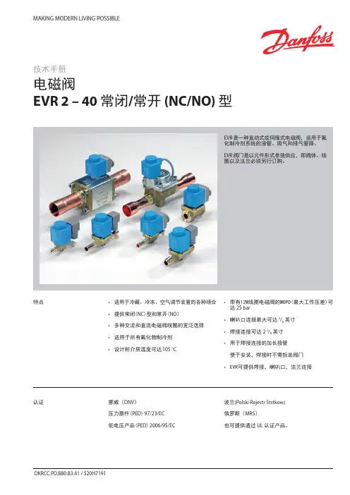
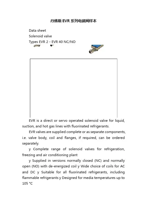
丹佛斯EVR系列电磁阀样本Data sheetSolenoid valveTypes EVR 2 - EVR 40 NC/NOEVR is a direct or servo operated solenoid valve for liquid, suction, and hot gas lines with fluorinated refrigerants.EVR valves are supplied complete or as separate components, i.e. valve body, coil and flanges, if required, can be ordered separately.y Complete range of solenoid valves for refrigeration, freezing and air conditioning planty Supplied in versions normally closed (NC) and normally open (NO) with de-energized coil y Wide choice of coils for AC and DC y Suitable for all fluorinated refrigerants, including flammable refrigerants y Designed for media temperatures up to 105 °Cy MOPD up to 25 bar with 12 W coil y Flare connections up to 5/8 in y Solder connections up to 2 1/8 iny Extended ends on solder versions make the installation easy. It is not necessary to dismantle the valve when soldering in y Available in flare, solder and flange connection versions FeaturesDet norske Veritas, DNVPressure Equipment Directive (PED) 97/23/EC Low Voltage Directive (LVD) 2006/95/ECPolski Rejestr Statków, Polen Maritime Register of Shipping, MRS Versions with UL approval can be supplied to order.ApprovalsData sheet Solenoid valve, types EVR 2 ? EVR 40 NC/NOTechnical data1) MOPD (Max. Opening Pressure Differential) for media in gas form is approx. 1 bar greater.2)Min. diff. pressure 0.07 bar is needed to stay open.RefrigerantsR22/R407C, R404A/R507, R410A, R134a, R407A, R23, R32, R290, R600, and R600a. For other refrigerants, contact Danfoss.Special note for R32, R290, R600, and R600a : Use only for system in compliance withstandard EN13463-1. Ignition risk is evaluated inaccordance with standard EN13463-1.Only EVR 2 - EVR 20 with solder connections andwithout manual stem can be applied in systemswith R32, R290, R600, and R600a as the workingfluid. For countries where safety standards are not an indispensable part of the safety system Danfoss recommends the installer to seek third partyapproval for systems containing R32, R290, R600, Note, please follow specific selection criteria stated in the datasheet for these particular refrigerants.Temperature of medium-40 –105 °C with 10 W or 12 W coil.Max. 130 °C during defrosting.Ambient temperature and enclosure for coil See separate data sheet for coils and ATEX coils.Capacity The capacity of the valve depends on the flow direction, see K v values from the table.The K v value is the water flow in [m 3/h] at a pressure drop across valve of 1 bar, ρ = 1000 kg/m 3.See extended capacity tables later in this datasheet.Table of contentsTechnical data...................................................................................................................... .......................................................2Rated capacity [kW] .................................................................................................................................................................3Ordering .............................................................. .........................................................................................................................4C apacity,Liquid .................................................................................................................. .......................................................7Capacity,Suction ............................................................................................................... ......................................................11Capacity, Hot gas ....................................................................................................................... .............................................19Design .............................................................. .. (40)Function.............................................................................................................. .......................................................................42Material specifications ................................................................................................... ......................................................43Dimensions and weights .. (45) Data sheet Solenoid valve, types EVR 2 ? EVR 40 NC/NORated liquid and suction vapour capacity is based on evaporating temperature t e = -10 °C, liquid temperature ahead of valve t l = 25 °C, pr essure drop in valve ?p = 0.15 bar.Rated hot gas capacity is based on condensing temperature t c = 40 °C, pressure drop across valve ?p = 0.8 bar, hot gas temperature t h = 65 °C,and subcooling of refrigerant ?tsub = 4 K.Rated capacity [kW]Data sheet Solenoid valve, types EVR 2 ? EVR 40 NC/NOOrdering (continued)EVR solder connections, Normally Closed (NC) - separate valve bodiesData sheet Solenoid valve, types EVR 2 ? EVR 40 NC/NOThe normal range of coils can be used for the NO valves, with the exception of the double frequency versions of 110 V, 50/60 Hz and 220 V, 50/60 Hz.Ordering (continued)EVR solder connections, Normally Open (NO) - separate valve bodiesValve bodies are supplied without flare nuts. Separate flare nuts:– 1/4 in or 6 mm, code no. 011L1101 – 3/8 in or 10 mm, code no. 011L1135 – 1/2 in or 12 mm, code no. 011L1103 – 5/8 in or 16 mm, code no. 011L1167OrderingEVR flare connections, Normally Closed (NC) - separate valve bodiesSee separate data sheet for coils.The normal range of coils can be used for the NO valves, with the exception of the double frequency versions of 110 V, 50/60 Hz and 220 V, 50/60 Hz.Data sheet Solenoid valve, types EVR 2 ? EVR 40 NC/NO Ordering (continued)Separate valve bodies, normally closed (NC)See separate data sheet for coils.Flange setsAccessoriesEVR 15 without manual operation, code no. 032F1224? in weld flange set, code no. 027N1115+ coil with terminal box, 220 V, 50 Hz, code no. 018F6701See separate data sheet for coils.ExampleCapacities are based on:– liquid temperaturet l = 25 °C ahead of valve, – evaporating temperature t e = -10 °C, superheat 0 K.Correction factorsWhen sizing valves, the plant capacity must be multiplied by a correction factor depending on liquid temperature t l ahead of valve/evaporator.When the corrected capacity is known,the selection can be made from the table.R22/R407CCorrection factors based on liquid temperature t lLiquidCapacities are based on:– liquid temperaturet l = 25 °C ahead of valve, – evaporating temperature t e = -10 °C, superheat 0 K.Correction factorsWhen sizing valves, the plant capacity must be multiplied by a correction factor depending on liquid temperature t l ahead ofWhen the corrected capacity is known,the selection can be made from the table.Correction factors based on liquid temperature t lR404A/R507Liquid (continued)Capacities are based on:– liquid temperaturet l = 25 °C ahead of valve, – evaporating temperature t e = -10 °C, superheat 0 K.Correction factorsWhen sizing valves, the plant capacity must be multiplied by a correction factor depending on liquid temperature t l ahead ofWhen the corrected capacity is known,the selection can be made from the table. Correction factors based on liquid temperature t lR290Liquid (continued)Data sheet Solenoid valve, types EVR 2 ? EVR 40 NC/NOCapacities are based on:– liquid temperaturet l = 25 °C ahead of valve, – evaporating temperature t e = -10 °C, superheat 0 K.Correction factorsWhen sizing valves, the plant capacity must be multiplied by a correction factor depending on liquid temperature t l ahead of valve/evaporator.When the corrected capacity is known,the selection can be made from the table.Correction factors based on liquid temperature t lR600Capacity Liquid (continued)Data sheetSolenoid valve, types EVR 2 ? EVR 40 NC/NOR22/R407CCorrection factorsWhen sizing valves, the evaporator capacity must be multiplied by a correction factor depending on liquid temperature t l ahead of expansion valve.When the corrected capacity is known, the selection can be made from the table.Correction factors for evaporating temperature tlCapacities are based on liquid temperature t l = 25 °C ahead of evaporator. The table values refer to the evaporator capacity and are given as a function ofevaporating temperature t e and pressure drop ?p across valve.Capacities are based on dry, saturated vapour ahead of valve.During operation with superheated vapour ahead of valve, the capacities are reduced by 4% for each 10 K superheat.Capacity SuctionData sheet Solenoid valve, types EVR 2 ? EVR 40 NC/NOCapacities are based on liquid temperature t l = 25 °C ahead of evaporator. The table values refer to the evaporator capacity and are given as a function ofevaporating temperature t e and pressure drop ?p across valve.Capacities are based on dry, saturated vapour ahead of valve.During operation with superheated vapour ahead of valve, the capacities are reduced by 4% for each 10 K superheat.Correction factors based on evaporating temperature t lCorrection factorsWhen sizing valves, the evaporator capacity must be multiplied by a correction factor depending on liquid temperature t l ahead of expansion valve.When the corrected capacity is known,the selection can be made from the table.R134aCapacity Suction(continued)Data sheet Solenoid valve, types EVR 2 ? EVR 40 NC/NOCorrection factors based on evaporating temperature t lCorrection factors When sizing valves, the evaporator capacity must be multiplied by a correction factor depending on liquid temperature t l ahead of expansion valve.When the corrected capacity is known,the selection can be made from the table.R404A/R507Capacities are based on liquid temperature t l = 25 °C ahead of evaporator. The table values refer to the evaporator capacity and are given as a function ofevaporating temperature t e and pressure drop ?p across valve.Capacities are based on dry, saturated vapour ahead of valve.During operation with superheated vapour ahead of valve, the capacities are reduced by 4% for each 10 K superheat.Capacity Suction(continued)Data sheet Solenoid valve, types EVR 2 ? EVR 40 NC/NOCorrection factors based on evaporating temperature t lCorrection factorsWhen sizing valves, the evaporator capacity must be multiplied by a correction factor depending on liquid temperature t l ahead of expansion valve.When the corrected capacity is known,the selection can be made from the table.R32Capacities are based on liquid temperature t l = 25 °C ahead of evaporator. The table values refer to the evaporator capacity and are given as a function ofevaporating temperature t e and pressure drop ?p across valve.Capacities are based on dry, saturated vapour ahead of valve.During operation with superheated vapour ahead of valve, the capacities are reduced by 4% for each 10 K superheat.Capacity Suction(continued)Data sheet Solenoid valve, types EVR 2 ? EVR 40 NC/NOCorrection factors based on evaporating temperature t lCorrection factorsWhen sizing valves, the evaporator capacity must be multiplied by a correction factor depending on liquid temperature t l ahead of expansion valve.When the corrected capacity is known,the selection can be made from the table.R290Capacities are based on liquid temperature t l = 25 °C ahead of evaporator. The table values refer to the evaporator capacity and are given as a function ofevaporating temperature t e and pressure drop ?p across valve.Capacities are based on dry, saturated vapour ahead of valve.During operation with superheated vapour ahead of valve,the capacities are reduced by 4% for each 10 K superheat.Capacity Suction(continued)Data sheet Solenoid valve, types EVR 2 ? EVR 40 NC/NOCorrection factors based on evaporating temperature t lCorrection factorsWhen sizing valves, the evaporator capacity must be multiplied by a correction factor depending on liquid temperature t l ahead of expansion valve.When the corrected capacity is known,the selection can be made from the table.R600Capacities are based on liquid temperature t l = 25 °C ahead of evaporator. The table values refer to the evaporator capacity and are given as a function ofevaporating temperature t e and pressure drop ?p across valve.Capacities are based on dry, saturated vapour ahead of valve.During operation with superheated vapour ahead of valve, the capacities are reduced by 4% for each 10 K superheat.Capacity Suction(continued)Data sheet Solenoid valve, types EVR 2 ? EVR 40 NC/NOCorrection factors based on evaporating temperature t lCorrection factorsWhen sizing valves, the evaporator capacity must be multiplied by a correction factor depending on liquid temperature t l ahead of expansion valve.When the corrected capacity is known,the selection can be made from the table.R600aCapacities are based on liquid temperature t l = 25 °C ahead of evaporator. The table values refer to the evaporator capacity and are given as a function ofevaporating temperature t e and pressure drop ?p across valve.Capacities are based on dry, saturated vapour ahead of valve.During operation with superheated vapour ahead of valve, the capacities are reduced by 4% for each 10 K superheat.Capacity Suction(continued)Data sheet Solenoid valve, types EVR 2 ? EVR 40 NC/NO Hot gas defrostingWith hot gas defrosting it is not normally possible to select a valve from condensing temperature t c and evaporating temperature t e .This is because the pressure in the evaporator as a rule quickly rises to a value near that of the condensing pressure. It remains at this value until the defrosting is finished.In most cases therefore, the valve will be selected from condensing temperature t c and pressure drop ?p across the valve, as shown in the example for heat recovery.Heat recovery The following is given: y Refrigerant = R22/R407Cy Evaporating temperature t e = -30 °C y Condensingtemperature t c = 40 °Cy Hot gas temperature ahead of valve t h = 85 °Cy Heat recovery condenser yield Q h = 8 kWThe capacity table for R22/R407C with t c = 40 °C gives the capacity for an EVR 10 as 8.9 kW, when pressure drop ?p is 0.2 bar.The required capacity is calculated as :Q table = f evaporator x f hot_temperature x Q hThe correction factor for t e = -30 °C is given in the table as 0.95.The correction for hot gas temperature t h = 85 °C has been calculated as 4% which corresponds to a factor of 1.04.Q h must be corrected with factors found: With ?p = 0.2 baris Q h = 8.71 x 0.95 x 1.04 = 8.6 kW.With ?p = 0.1 bar, Q h becomes only 6.19 x 0.95 x 1.04 = 6.1 kW.An EVR 6 would also be able to give the required capacity, but with ?p at approx. 1 bar. The EVR 6 is therefore too small.The EVR 15 is so large that it is doubtful whether the necessary ?p of approx. 0.1 bar could be obtained.An EVR 15 would therefore be too large.Result: An EVR 10 is the correct valve for the given conditions.Capacity Suction (continued)Data sheetSolenoid valve, types EVR 2 ? EVR 40 NC/NOR22/R407CAn increase in hot gas temperature t h of 10 K, based on t h = t c +25 °C, reduces valve capacity approx. 2% and vice versa.A change in evaporating temperature t e changes valve capacity; see correction factor table below.Correction factorsWhen sizing valves, the table value mustbe multiplied by a correction factor depending on evaporating temperature t e .Correction factors for evaporating temperature teCapacity Hot gas。
装配说明� ���
目录� ��
EVR2 - 40 预防措施 (15)
当测试压力时 (16)
线圈 (17)
正确的产品 (18)
注释
Af0_0006
装配说明� ���
应。
如果不对应,则可能会烧毁线圈。
始终确
保阀门与线圈相匹配。
当更换 EVR 20 NC 中的线圈时(NC = 常闭),
请注意:
- 使用交流线圈的阀体有一个方形衔铁。
衔铁。
- 使用直流线圈的阀体有一个圆形衔铁。
衔铁。
安装错误的线圈会导致较小的MOPD M OPD 。
请查看顶
部螺母上的数据。
应尽可能始终选择单频线圈,
因为单频线圈发热量要低于双频线圈。
对于阀门在大多数工作时间内必须保持闭合
(未通电)的系统,应使用 NC (常闭)电磁
阀。
对于阀门在大多数工作时间内必须保持开
启(未通电)的系统,应使用 NO (常开)电
磁阀。
不能使用 NC (常闭)电磁阀来替换NO
NO (常开)电磁阀,反之亦然。
每个可夹式线圈上有两个标签(请参见图
解)。
粘贴式标签粘在线圈的一侧,另一个打孔式标签
在线圈安装到位前贴在衔铁上。
衔铁上。
上。
Af0_0015
Af0_0020
(“以前的”线圈型号)(新型“可夹式”线圈)“可夹式”线圈)可夹式”线圈)式”线圈)”线圈)线圈)。

MAKING MODERN LIVING POSSIBLE
安装指导
EVRA系列电磁阀
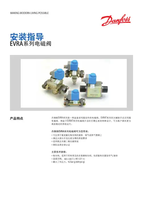
产品特点丹佛斯EVRA系列是一种直接或伺服动作的电磁阀;EVRAT系列则为辅助开启式伺服
电磁阀。
得益于EVRAT系列电磁阀开启时无需压差的特殊设计,可为客户提供更为
高效稳定的系统运行。
丹佛斯EVRA系列电磁阀可为您带来:
◈可应用于氨或氟化制冷剂的液体、吸气或热气管路上
◈满足大部分开启压差为零的系统要求
◈适用高压冷媒二氧化碳系统
◈国际品质全球认证
主要技术参数:
◈制冷剂:适用于所有常见的非易燃制冷剂,包括氨和非腐蚀性气/液体
◈温度范围:-40/+105℃ (-40/+221℉)
◈最大工作压力:42 bar g (609 psi g)。
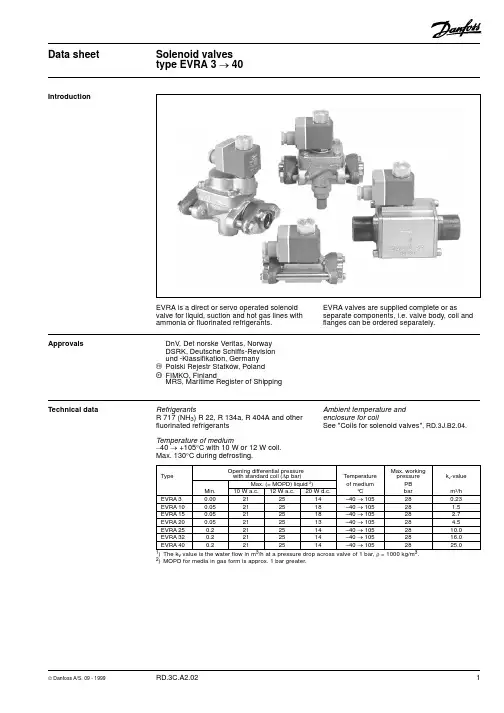
Data sheetSolenoid valves type EVRA 3 ® 40IntroductionEVRA is a direct or servo operated solenoid valve for liquid, suction and hot gas lines with ammonia or fluorinated refrigerants.EVRA valves are supplied complete or asseparate components, i.e. valve body, coil and flanges can be ordered separately.ApprovalsDnV, Det norske Veritas, Norway DSRK, Deutsche Schiffs-Revision und -Klassifikation, Germany P Polski Rejestr Statków, Poland W FIMKO, FinlandMRS, Maritime Register of ShippingTechnical dataRefrigerantsR 717 (NH 3) R 22, R 134a, R 404A and other fluorinated refrigerantsTemperature of medium-40 ® +105°C with 10 W or 12 W coil.Max. 130°C during defrosting.Ambient temperature and enclosure for coilSee "Coils for solenoid valves", RD.3J.B2.04.1)The k vvalue is the water flow in m 3/h at a pressure drop across valve of 1 bar, r = 1000 kg/m 3.2)MOPD for media in gas form is approx. 1 bar greater.Opening differential pressure Max. working Typewith standard coil (D p bar)Temperature pressurek v -value Max. (= MOPD) liquid 2)of medium PBMin.10 W a.c.12 W a.c.20 W d.c.°C barm 3/h EVRA 30.00212514–40 ® 105280.23EVRA 100.05212518–40 ® 10528 1.5EVRA 150.05212518–40 ® 10528 2.7EVRA 200.05212513–40 ® 10528 4.5EVRA 250.2212514–40 ® 1052810.0EVRA 320.2212514–40 ® 1052816.0EVRA 400.2212514–40 ® 1052825.0Data sheet Solenoid valves, type EVRA 3 ® 40Technical data (continued)1)Rated liquid and suction vapour capacity is based on evaporating temperature t e = -10°C, liquid temperature ahead of valve t l = +25°C,and pressure drop across valve D p = 0.15 bar.Rated capacity 1) [kW]TypeLiquidSuction vapourHot gasR717R22R134a R404AR717R22R134a R404AR717R22R134a R404A EVRA321.8 4.6 4.3 3.2 6.5 2.1 1.7 1.7EVRA10142.030.227.821.19.0 3.4 2.5 3.142.613.911.011.3EVRA15256.054.450.138.016.1 6.2 4.4 5.576.724.919.820.3EVRA20426.090.683.563.326.910.37.39.2128.041.532.933.9EVRA25947.0201.0186.0141.059.722.816.320.4284.092.373.275.3EVRA321515.0322.0297.0225.095.536.526.132.6454.0148.0117.0120.0EVRA402368.0503.0464.0351.0149.057.040.851.0710.0231.0183.0188.0CoilsSee "Coils for solenoid valves", RD.3J.B2.02.AccessoriesStrainer FA for direct mounting, see "FA".ExampleEVRA 15 complete valve with terminal box,220 V, 50 Hz, code no. 032F6218+ 3/4 in. weld flange set, code no. 027N1120.ExampleEVRA 15 valve body with manual operation,code no. 032F6215+ 3/4 in. weld flange set, code no. 027N1120+ coil with terminal box, 220 V, 50 Hz,code no. 018Z6701(see "Coils for solenoid valves").Flange set3/8027N11121/2027N11155/816027L1117027L11163/4027N11207/822027L1123027L11223/4027N12207/822027L1223027L12221027N122511/828027L1229027L12281027N122511/4027N1130Connection in.mmin.mmin.Solder Weld Code no.Valve typeEVRA 3,10 and 15EVRA 20and 25Separate valve bodiesCode no.TypeConnectionRequired Steel GGG-40.3GG-25GGG-40.3coil typeValve house with necessary flange gasket and bolts;Weld connection (without coil)(without coil and flanges)Valves with manual operation EVRA 10 a.c. / d.c.-032F6210--EVRA 15Se table a.c. / d.c.-032F6215--EVRA 20Flange set a.c.-032F6220--EVRA 20 d.c.-032F6221--EVRA 25 a.c. / d.c.-032F6225--EVRA 3211/4 in. a.c. / d.c.-042H1121042H1126EVRA 4011/2 in. a.c. / d.c.-042H1123042H1128Valves without manual operation EVRA 3Se table a.c. / d.c.032F3050---EVRA 10Flange set a.c. / d.c.-032F6211--EVRA 25 a.c. / d.c.-032F6226--EVRA 3211/4 in. a.c. / d.c.--042H1122042H1127EVRA 4011/2 in.a.c. / d.c.--042H1124042H1129Ordering Complete valves without flangesCode no. 1)TypeConnectionSteel GGG-40.3Steel GGG-40.310 W coil with 1 m cable10 W coil with terminal boxValves without manual operation EVRA 3Se table Flange set032F3102-032F3013-EVRA 10-032F6207-032F6208Valves with manual operation EVRA 10-032F6212-032F6213EVRA 15Se table Flange set -032F6217-032F6218EVRA 20-032F6222-032F62231)Valve body with gaskets, bolts and 10 W a.c. coil. Please specify code no., voltage and frequency. Voltage and frequency can also be given in the form of an appendix number, see table "Appendix numbers", under EVR.Rated hot gas capacity is based on condensing tempera-ture t c = +40°C,pressure drop across valve D p = 0.8 bar,hot gas temperature t h = +65°C,and subcooling of refrigerant D t sub = 4 K.Data sheet Solenoid valves, type EVRA 3 ® 40Capacity Liquid capacity Q l kWR 717 (NH 3)EVRA 317.825.130.835.639.8EVRA 10116.0164.0201.0232.0259.0EVRA 15209.0295.0362.0418.0467.0EVRA 20348.0492.0603.0696.0778.0EVRA 25773.01093.01340.01547.01729.0EVRA 321237.01749.02144.02475.02766.0EVRA 401933.02734.03349.03867.04322.0TypeLiquid capacity Q e kW at pressure drop across valve D p bar0.10.20.30.40.5R 22EVRA 3 3.8 5.3 6.67.68.5EVRA 1024.734.942.749.355.1EVRA 1544.462.876.988.899.2EVRA 2073.9105.0128.0148.0165.0EVRA 25165.0232.0285.0329.0368.0EVRA 32263.0372.0455.0526.0588.0EVRA 40411.0581.0712.0822.0919.0R 134aEVRA 3 3.5 4.9 6.07.07.8EVRA 1022.732.239.445.550.8EVRA 1540.957.970.981.891.5EVRA 2068.296.5118.0136.0153.0EVRA 25152.0214.0263.0303.0339.0EVRA 32243.0343.0420.0485.0542.0EVRA 40379.0536.0656.0758.0847.0R 404AEVRA 3 2.6 3.7 4.6 5.3 5.9EVRA 1017.224.329.834.438.5EVRA 1531.043.853.762.069.3EVRA 2051.773.089.5103.0116.0EVRA 25115.0162.0199.0230.0257.0EVRA 32184.0260.0318.0367.0411.0EVRA 40287.0406.0497.0574.0642.0Capacities are based on liquid temperature t l = +25°C ahead of valve, evaporating temperature t e = -10°C, and superheat 0 K.Correction factorsWhen sizing valves, the plant capacity must be multiplied by a correction factor depending on liquid temperature t l ahead of valve/evaporator.When the corrected capacity is known, the selection can be made from the table.t l °C -100+10+20+25+30+40+50R 717 (NH 3)0.840.880.920.97 1.0 1.03 1.09 1.16R 22, R 134a 0.760.810.880.96 1.0 1.05 1.16 1.31R 404A0.700.760.840.941.01.071.241.47Data sheet Solenoid valves, type EVRA 3 ® 40Capacity (continued)Suction vapour capacity Q e kWTypeSuction vapour capacity Q e kW at evaporating temperature t e °C –40–30–20–10+10R 717 (NH 3)0.1 3.4 4.5 5.97.38.910.6EVRA 100.15 4.0 5.47.09.010.913.00.2 4.5 6.17.910.012.615.00.1 6.18.110.713.216.019.1EVRA 150.157.29.712.516.119.623.40.28.011.014.218.022.627.00.110.213.517.821.926.631.9EVRA 200.1512.116.120.926.932.639.00.213.418.323.729.937.745.10.122.630.039.548.759.270.8EVRA 250.1526.735.946.359.772.586.70.229.840.552.766.483.7100.00.136.247.863.277.994.7113.0EVRA 320.1542.757.474.195.5116.0139.00.247.764.884.3106.0134.0160.00.156.574.898.8122.0148.0177.0EVRA 400.1566.889.8116.0149.0181.0217.00.274.5101.0132.0166.0209.0251.0R 220.1 1.4 1.8 2.3 2.8 3.4 4.0EVRA 100.15 1.6 2.1 2.7 3.4 4.1 4.90.2 1.8 2.4 3.1 3.8 4.8 5.60.1 2.5 3.2 4.1 5.0 6.17.2EVRA 150.15 2.9 3.8 4.8 6.27.48.80.2 3.3 4.3 5.5 6.88.610.20.1 4.1 5.3 6.88.410.112.0EVRA 200.15 4.9 6.48.110.312.314.70.2 5.57.29.211.414.316.90.19.111.815.218.622.426.6EVRA 250.1510.914.217.922.827.432.60.212.216.120.425.331.737.60.114.618.924.329.835.842.6EVRA 320.1517.422.728.836.543.852.20.219.625.732.640.550.760.20.122.829.538.146.556.066.5EVRA 400.1527.235.445.057.068.681.50.230.540.251.063.379.294.0Capacities are based on liquid temperature t l = +25°C ahead of evaporator.The table values refer to theevaporator capacity and are given as a function of evaporatingtemperature t e and pressure drop D p across valve.Capacities are based on dry,saturated vapour ahead of valve.During operation with superheated vapour ahead of valve, thecapacities are reduced by 4% for each 10 K superheat.Pressure drop across valve D p bart l °C -100+10+20+25+30+40+50R 717 (NH 3)0.840.880.920.97 1.0 1.03 1.09 1.16R 220.760.810.880.961.01.051.161.31Correction factorsWhen sizing valves, the evaporator capacity must be multiplied by a correction factor depending on liquid temperature t l ahead of expansion valve.When the corrected capacity is known, the selection can be made from the table.Data sheet Solenoid valves, type EVRA 3 ® 40Capacity (continued)Suction vapour capacity Q e kWR 134a0.10.87 1.2 1.6 2.1 2.6 3.2EVRA 100.150.99 1.4 1.9 2.4 3.2 3.90.2 1.1 1.6 2.1 2.8 3.5 4.50.1 1.6 2.1 2.8 3.8 4.7 5.7EVRA 150.15 1.8 2.5 3.4 4.4 5.77.00.2 2.0 2.8 3.8 5.0 6.38.10.1 2.6 3.6 4.7 6.37.89.5EVRA 200.15 3.0 4.2 5.67.39.511.70.2 3.3 4.7 6.48.310.513.50.1 5.87.910.513.917.221.1EVRA 250.15 6.69.312.516.321.125.90.27.310.414.118.523.429.90.19.312.616.822.227.733.8EVRA 320.1510.614.920.026.133.841.40.211.716.622.629.637.447.80.114.519.826.334.843.352.8EVRA 400.1516.523.331.340.852.864.80.218.326.035.346.358.574.8R 404A0.1 1.2 1.5 2.0 2.5 3.1 3.7EVRA 100.15 1.4 1.8 2.4 3.1 3.8 4.60.2 1.6 2.1 2.7 3.4 4.3 5.30.1 2.1 2.7 3.6 4.5 5.5 6.6EVRA 150.15 2.5 3.3 4.3 5.5 6.88.20.2 2.8 3.7 4.9 6.17.89.50.1 3.5 4.6 6.07.59.211.1EVRA 200.15 4.1 5.57.19.211.313.60.2 4.6 6.28.110.213.015.80.17.710.113.316.620.424.6EVRA 250.159.112.115.820.425.030.30.210.313.818.022.728.835.00.112.316.221.326.632.639.4EVRA 320.1514.619.425.332.640.048.50.216.522.028.836.346.156.00.119.325.333.341.551.061.5EVRA 400.1522.930.339.551.062.575.60.225.834.545.056.872.187.5Capacities are based on liquid temperature t l = +25°C ahead of evaporator.The table values refer to theevaporator capacity and are given as a function of evaporatingtemperature t e and pressure drop D p across valve.Capacities are based on dry,saturated vapour ahead of valve.During operation with superheated vapour ahead of valve, thecapacities are reduced by 4% for each 10 K superheat.Correction factorsWhen sizing valves, the evaporator capacity must be multiplied by a correction factor depending on liquid temperature t l ahead of expansion valve.When the corrected capacity is known, the selection can be made from the table.TypeSuction vapour capacity Q e kW at evaporating temperature t e °C –40–30–20–10+10Pressure drop across valve D p bart l °C -100+10+20+25+30+40+50R 134a 0.760.810.880.96 1.0 1.05 1.16 1.31R 404A0.700.760.840.941.01.071.241.47Data sheet Solenoid valves, type EVRA 3 ® 40Capacity (continued)R 717 (NH 3)Hot gas capacity Q h kW+20+30+40+50+600.1 1.8 2.1 2.3 2.5 2.60.2 2.6 2.9 3.2 3.5 3.7EVRA 30.4 3.8 4.2 4.6 4.9 5.30.8 5.1 6.0 6.57.17.61.67.48.39.19.910.90.112.013.414.716.017.20.217.119.020.922.724.4EVRA 100.424.527.129.732.234.70.834.039.042.646.149.51.648.553.859.164.371.30.121.724.126.428.831.00.230.834.237.540.844.0EVRA 150.444.148.853.558.062.40.861.270.376.783.089.11.687.496.9106.0116.0128.00.136.140.144.048.051.70.251.457.062.668.073.2EVRA 200.473.581.389.196.7104.00.8102.0117.0128.0138.0148.01.6146.0161.0177.0193.0214.00.180.289.198.0107.0115.00.2114.0127.0139.0151.0163.0EVRA 250.4163.0181.0198.0215.0231.00.8227.0260.0284.0307.0330.01.6324.0358.0394.0429.0475.00.1128.0143.0157.0171.0184.00.2183.0203.0223.0242.0260.0EVRA 320.4261.0289.0317.0344.0370.00.8362.0416.0455.0492.0528.01.6518.0574.0631.0688.0761.00.1201.0223.0244.0267.0287.00.2286.0317.0348.0378.0407.0EVRA 400.4408.0452.0495.0537.0578.00.8566.0650.0710.0769.0825.01.6809.0897.0986.01074.01188.0TypeD p bar Hot gas capacity Q e kWEvaporating temp. t e = -10°C. Hot gas temp. t h = t c + 25°C. Subcooling D t sub = 4 K.Correction factorWhen sizing valves, the table value must be multiplied by a correction factor depending on evaporating temperature t e .Pressure drop across valveCondensing temperature t c °Ct e °C-40-30-20-100+10R 717 (NH 3)0.890.910.961.01.061.10An increase in hot gas temperature t h of 10 K, based on t h = t c +25°C,reduces valve capacity approx. 2%and vice versa.A change in evaporatingtemperature t e changes valvecapacity; see correction factor table below.Data sheet Solenoid valves, type EVRA 3 ® 40Capacity (continued)R 22Hot gas capacity Q h kW+20+30+40+50+600.10.680.720.760.780.790.20.97 1.0 1.1 1.1 1.1EVRA 30.4 1.4 1.5 1.5 1.6 1.60.8 1.9 2.0 2.1 2.3 2.31.6 2.7 2.9 3.0 3.1 3.20.1 4.4 4.7 4.9 5.1 5.20.2 6.3 6.77.07.27.3EVRA 100.49.09.610.010.310.40.812.413.213.914.714.91.617.518.619.620.220.50.18.08.58.99.29.30.211.412.112.613.013.2EVRA 150.416.317.218.018.518.70.822.323.124.926.526.81.631.533.535.236.436.90.113.314.114.815.315.50.219.020.121.021.722.0EVRA 200.427.128.730.030.931.20.837.138.441.544.244.61.652.555.958.660.661.50.129.631.432.934.034.40.242.144.646.748.248.8EVRA 250.460.263.866.668.669.40.882.587.992.398.299.21.6117.0124.0130.0135.0137.00.147.450.252.654.455.00.267.471.474.777.178.1EVRA 320.496.3102.0107.0110.0111.00.8132.0140.0148.0157.0159.01.6187.0199.0209.0216.0219.00.174.078.582.385.086.00.2105.0112.0117.0121.0122.0EVRA 400.4151.0159.0167.0172.0174.00.8206.0222.0231.0246.0248.01.6291.0310.0326.0337.0342.0TypeD p bar Hot gas capacity Q e kWEvaporating temp. t e = -10°C. Hot gas temp. t h = t c + 25°C. Subcooling D t sub = 4 K.Correction factorWhen sizing valves, the table value must be multiplied by a correction factor depending on evaporating temperature t e .Pressure drop across valveCondensing temperature t c °Ct e °C -40-30-20-100+10R 220.900.940.971.01.031.05An increase in hot gas temperature t h of 10 K, based on t h = t c +25°C,reduces valve capacity approx. 2%and vice versa.A change in evaporatingtemperature t e changes valvecapacity; see correction factor table below.Data sheet Solenoid valves, type EVRA 3 ® 40Capacity (continued)R 134aHot gas capacity Q h kW+20+30+40+50+600.10.540.570.60.610.60.20.770.820.850.860.85EVRA 30.4 1.1 1.2 1.2 1.2 1.20.8 1.5 1.6 1.7 1.8 1.81.6 2.2 2.3 2.4 2.5 2.40.1 3.5 3.7 3.9 4.0 3.90.2 5.0 5.3 5.5 5.6 5.6EVRA 100.47.07.77.98.07.90.89.910.511.011.611.41.614.315.115.716.015.90.1 6.4 6.77.07.17.10.29.19.610.010.110.0EVRA 150.412.613.814.214.414.30.817.919.019.820.820.51.625.727.228.228.828.60.110.611.211.711.811.80.215.116.016.616.816.7EVRA 200.421.022.923.724.023.80.829.831.633.034.734.21.642.845.347.147.947.60.123.624.925.926.426.20.233.635.536.837.437.1EVRA 250.446.651.052.753.452.90.866.270.273.277.076.01.695.2101.0105.0107.0106.00.137.639.841.442.141.80.253.856.858.959.859.4EVRA 320.474.781.684.385.484.60.8106.0112.0117.0123.0122.01.6152.0161.0167.0170.0169.00.158.862.364.765.865.30.284.188.892.193.592.8EVRA 400.4117.0127.0132.0134.0132.00.8166.0176.0183.0192.0190.01.6238.0252.0262.0266.0265.0TypeD p bar Hot gas capacity Q e kWEvaporating temp. t e = -10°C. Hot gas temp. t h = t c + 25°C. Subcooling D t sub = 4 K.Correction factorWhen sizing valves, the table value must be multiplied by a correction factor depending on evaporating temperature t e .Pressure drop across valveCondensing temperature t c °Ct e °C -40-30-20-100+10R 134a0.880.920.981.01.041.08An increase in hot gas temperature t h of 10 K, based on t h = t c +25°C,reduces valve capacity approx. 2%and vice versa.A change in evaporatingtemperature t e changes valvecapacity; see correction factor table below.Data sheet Solenoid valves, type EVRA 3 ® 40Capacity (continued)R 404AHot gas capacity Q h kW+20+30+40+50+600.10.620.630.620.590.540.20.870.890.880.830.76EVRA 30.4 1.2 1.3 1.3 1.2 1.10.8 1.7 1.7 1.7 1.7 1.51.6 2.4 2.5 2.4 2.3 2.10.1 4.0 4.1 4.0 3.8 3.50.2 5.7 5.8 5.7 5.5 5.0EVRA 100.48.18.28.27.87.00.811.111.411.311.110.11.615.716.015.815.213.90.17.37.47.3 6.9 6.30.210.210.410.39.88.9EVRA 150.414.614.814.714.012.70.820.120.420.320.018.11.628.328.828.427.425.00.112.112.312.111.510.50.217.117.317.216.314.9EVRA 200.424.424.724.523.321.10.833.434.033.933.330.21.647.148.047.445.641.60.126.827.426.925.623.30.237.938.438.236.333.0EVRA 250.454.254.954.551.747.00.874.275.675.374.067.21.6105.0107.0105.0101.092.50.143.043.843.040.937.30.260.661.461.158.152.8EVRA 320.486.787.887.282.775.20.8119.0121.0120.0118.0107.01.6167.0171.0168.0162.0148.00.167.068.567.364.058.30.294.896.095.590.882.5EVRA 400.4136.0137.0136.0129.0117.00.8186.0189.0188.0185.0168.01.6262.0266.0263.0253.0231.0TypeD p bar Hot gas capacity Q e kWEvaporating temp. t e = -10°C. Hot gas temp. t h = t c + 25°C. Subcooling D t sub = 4 K.Correction factorWhen sizing valves, the table value must be multiplied by a correction factor depending on evaporating temperature t e .Pressure drop across valveCondensing temperature t c °Ct e °C -40-30-20-100+10R 404A0.860.880.931.01.031.07An increase in hot gas temperature t h of 10 K, based on t h = t c +25°C,reduces valve capacity approx. 2%and vice versa.A change in evaporatingtemperature t e changes valvecapacity; see correction factor table below.Data sheet Solenoid valves, type EVRA 3 ® 40Capacity (continued)Hot gas capacity G h kg/sHot gas capacity G h kg/s at pressure drop across valve D p bar TypeHot gastemperaturet h°CCondensingtemperaturet c°C0.512345678+250.0030.0050.0060.0070.0070.0070.0070.0070.007 EVRA 3+350.0040.0050.0070.0090.0090.010.010.010.01+450.0050.0060.0090.010.0110.0120.0130.0130.013+250.0220.030.040.0450.0480.0480.0480.0480.048 EVRA 10+350.0260.0360.0480.0560.0610.0640.0650.0650.065+450.0300.0410.0560.0660.0740.0790.0830.0850.086+250.0400.0540.0720.0810.0860.0870.0870.0870.087 EVRA 15+350.0460.0640.0860.10.1090.1150.1170.1170.117+450.0530.0740.1010.120.1330.1420.1490.1530.155+250.0660.090.120.120.1440.1450.1450.1450.145 EVRA 20+90+350.0770.1070.1440.1670.1820.1910.1950.1950.195+450.0890.1240.1690.1990.2110.2370.2480.2550.258+250.1430.1970.260.2960.3130.3160.3160.3160.316 EVRA 25+350.1680.2320.3130.3640.3970.4170.4250.4250.425+450.1940.2690.3680.4340.4820.516 1.540.5550.561+250.2330.3220.4240.4830.5110.516EVRA 32+350.2740.3790.5110.5940.6480.6810.694+450.3160.4390.6010.7090.7870.8420.8820.9060.916+250.3620.5030.6630.7550.7980.806EVRA 40+350.4290.5920.7980.929 1.013 1.064 1.084+450.4950.6860.939 1.107 1.23 1.316 1.378 1.416 1.431R 717 (NH3)+250.0080.0110.0140.0160.0170.0170.0170.0170.017 EVRA 3+350.0090.0120.0170.0190.0210.0220.0220.0220.022+450.0100.0140.0190.0220.0250.0260.0270.0280.028+250.0510.0690.0920.1040.1090.1110.1110.1110.111 EVRA 10+350.0580.080.1080.1250.1360.1420.1440.1440.144+450.0660.0920.1250.1460.1620.1720.1790.1830.183+250.0910.1250.1650.1870.1970.1990.1990.1990.199 EVRA 15+350.1050.1440.1940.2250.2440.2560.2580.2580.258+450.1190.1650.2240.2630.2910.310.3220.3290.330+250.1520.2080.2750.3110.3280.3320.3320.3320.332 EVRA 20+90+350.1740.2410.3230.3750.4070.4250.4310.4310.431+450.1930.2750.3740.4390.4850.5160.5370.5480.55+250.3310.4530.5990.6770.7150.7220.7220.7220.722 EVRA 25+350.380.5240.7040.8160.8860.9250.9380.9380.938+450.4310.5980.8140.956 1.056 1.125 1.169 1.192 1.197+250.5390.7390.976 1.106 1.168 1.179EVRA 32+350.6190.856 1.15 1.331 1.446 1.509 1.531+450.7040.978 1.329 1.562 1.723 1.837 1.909 1.947 1.955+250.843 1.155 1.525 1.728 1.825 1.843EVRA 40+350.968 1.338 1.798 2.08 2.26 2.358 2.393+45 1.1 1.528 2.078 2.44 2.693 2.87 2.383 3.043 3.055R 22An increase in hot gas temperature t h of 10K reduces valve capacity approx. 2% and vice versa.Capacity (continued)Hot gas capacity G h kg/sHot gas capacity G h kg/s at pressure drop across valve D p bar TypeHot gastemperaturet h°CCondensingtemperaturet c°C0.512345678+250.0070.0090.0110.0120.012EVRA 3+350.0090.0110.0140.0160.0160.0160.016+450.010.0120.0180.020.0210.0210.0210.0210.021+250.0480.060.0740.0770.077EVRA 10+350.0550.0710.0920.1030.1040.104+450.060.0840.1110.1270.1340.1350.1350.1350.135+250.0810.1080.1340.140.14EVRA 15+350.0940.1290.1660.1920.1870.1870.187+450.1080.1510.20.2280.2410.2440.2440.2440.244+250.1340.180.2230.2330.233EVRA 20+60+350.1570.2150.2760.3070.3120.3120.312+450.1810.2520.3330.3810.4030.4070.4070.4070.407+250.2920.3910.4860.5060.506EVRA 25+350.3410.4670.6020.6680.6790.6790.679+450.3930.5490.7250.830.8760.8850.8850.8850.885+250.4780.6380.793 1.8260.826EVRA 32+350.5560.7630.994 1.091 1.108 1.108 1.108+450.6410.897 1.197 1.354 1.432 1.446 1.446 1.446 1.446+250.7470.998 1.24 1.291 1.291EVRA 40+350.87 1.192 1.553 1.704 1.731 1.731 1.731+45 1.002 1.402 1.87 2.117 2.237 2.259 2.259 2.259R 134a+250.010.0130.0180.0210.0220.0230.0230.0230.023 EVRA 3+350.0110.0150.020.0240.0270.0280.0290.0290.03+450.0120.0170.0230.0280.0320.0340.0350.0360.037+250.0630.0870.1160.1340.1450.1480.1490.1490.149 EVRA 10+350.0720.10.1340.1580.1740.1840.190.190.192+450.0810.1120.1530.1820.2030.2280.2280.2370.239+250.1130.1570.210.2420.260.2670.2690.2690.269 EVRA 15+350.1290.180.2420.2850.3130.3320.3410.3420.346+450.1460.2020.2750.3270.3650.3930.4110.4240.431+250.1890.2620.350.4030.4330.4450.4490.4490.449 EVRA 20+60+350.2150.30.4040.4740.5210.5520.5690.570.576+450.2430.3370.4590.5450.6090.6560.6840.7070.719+250.4110.570.7630.8780.9420.9690.9780.9780.978 EVRA 25+350.4680.6530.881 1.032 1.136 1.203 1.239 1.241 1.253+450.5290.734 1.0 1.188 1.326 1.43 1.49 1.539 1.566+250.6720.931 1.245 1.432 1.539 1.581 1.581 1.581 1.581 EVRA 32+350.765 1.069 1.436 1.686 1.854 1.964 2.022 2.025 2.025+450.862 1.198 1.632 1.939 1.836 2.34 2.433 2.513 2.557+25 1.05 1.454 1.946 2.238 2.406 2.471 2.471 2.471 2.471 EVRA 40+35 1.195 1.657 2.245 2.635 2.897 3.068 3.161 3.166 3.166+45 1.348 1.873 2.55 3.03 3.384 3.65 3.801 3.926 3.995R 404AAn increase in hot gas temperature t h of 10K reduces valve capacity approx. 2% and vice versa.Design FunctionEVRA solenoid valves are designed on two different principles:1.Direct operation2.Servo operation1. Direct operationEVRA 3 is direct operated. The valve opens direct for full flow when the armature (16) moves up into the magnetic field of the coil. This means that the valve operates with a min. differential pressure of 0 bar.The teflon valve plate (18) is fitted direct on the armature (16).Inlet pressure acts from above on the armature and the valve plate. Thus, inlet pressure, spring force and the weight of the armature act to close the valve when the coil is currentless.2. Servo operationEVRA 10 ® 20 are servo operated with a "floating" diaphragm (80). The pilot orifice (29) of stainless steel is placed in the centre of the diaphragm. The teflon pilot valve plate (18) is fitted direct to the armature (16).When the coil is currentless, the main orifice and pilot orifice are closed. The pilot orifice and main orifice are held closed by the weight of the armature, the armature spring force and the differential pressure between inlet and outlet sides.When current is applied to the coil the armature is drawn up into the magnetic field and opens the pilot orifice. This relieves the pressure above the diaphragm, i.e. the space above the diaphragm becomes connected to the outlet side of the valve.The differential pressure between inlet and outlet sides then presses the diaphragm away from the main orifice and opens it for full flow. Thereforea certain minimum differential pressure is necessary to open the valve and keep it open. For EVRA 10 ® 20 valves this differential pressure is 0.05 bar.When current is switched off, the pilot orifice closes. Via the equalization holes (73) in the diaphragm, the pressure above the diaphragm then rises to the same value as the inlet pressure and the diaphragm closes the main orifice.EVRA 25, 32 and 40 are servo operated piston valves. The valves are closed with currentless coil.The servo piston (80) with main valve plate (84) closes against the valve seat (83) by means of the differential pressure between inlet and outlet side of the valve, the force of the compression spring (76) and possibly the piston weight. When current to the coil is switched on, the pilot orifice (29) opens. This relieves the pressure on the piston spring side of the valve. The differen-tial pressure will then open the valve.The minimum differential pressure needed for full opening of the valves is 0.07 bar.4.Coil 16.Armature18.Valve plate / Pilot valve plate 20.Earth terminal24.Connection for flexible steelhose28.Gasket29.Pilot orifice30.O-ring31.Piston ring36.DIN plug40.Terminal box43.Valve cover44.O-ring45.Valve cover gasket48.Flange gasket49.Valve body51.Cover / Threaded plug52.Lock button and top nut53.Manual operation spindle 59.Strainer73.Equalization hole74.Main channel75.Pilot channelpression spring80.Diaphragm/Servo piston82.Support washer83.Valve seat84.Main valve plate EVRA 3EVRA 10, 15 and 20 EVRA 25EVRA 32 and 40Dimensions and weightsEVRA 3 ® 20Coil with terminal boxWeight of coil10 W: approx. 0.3 kg12 and 20 W: approx. 0.5 kg Weight of flange setFor EVRA 3, 10 and 15: 0.6 kgFor EVRA 20: 0.9 kgEVRA 10 ® 20Coil with terminal boxEVRA 10Coil with terminal boxEVRA 3Coil with cableEVRA 3 ® 20Coil with DIN plugsmmmm mm mm mm mm mmmmmm mm kg 1) With coil, without flangesEVRA 38419124658068 1.2EVRA 102210081130688068 1.7EVRA 1510081130688068 1.8EVRA 20110771558596682.77585B 1max.Weight 1)L 5 max.12 W 20 W 10 W B H 1H 2H 3H 4L L 1TypeDimensions and weights (continued)Weight of coil10 W: approx. 0.3 kg12 and 20 W: approx. 0.5 kgWeight of flange set For EVRA 25: 0.9 kgEVRA 25Coil with terminal boxEVRA 32 and 40Coil with terminal boxEVRA 25Coil with terminal boxEVRA 25, 32 and 40Coil with DIN plugsEVRA 25, 32 and 40Coil with cable EVRA 32 and 40Coil with terminal boxmmmm mmmm mm mm mmmmmm mm kg EVRA 254614178162929568 3.0EVRA 32471155318075858068 4.0EVRA 40471155320080684.0B 1max.Weight 1)L 5 max.12 W 20 W 10 W B H 1H 2H 3H 4L L 1Type1) With coil, without flanges。
丹佛斯-AKS41-ICAD-EKC347电动阀使用说明书丹佛斯 AKS41 ICAD EKC347电动阀使用说明书本系统采用Danfoss的一套组合(AKS41液位传感器+(ICM+ICAD封闭式电动阀)+EKC347控制器)进行供液控制。
EKC347控制器可以根据AKS41液位传感器提供的4~20mA液位信号来精确控制ICM封闭式电动阀的开度。
以下分别给出AKS41液位传感器、ICAD电动阀马达(电动阀)、EKC347控制器的中文操作指南,如果与英文操作指南有冲突,以英文为准。
一、AKS41液位传感器、ICAD电动阀马达、EKC347控制器的初始设定AKS41液位传感器、ICAD电动阀马达、EKC347控制器必须进行初始设定。
1.1、液位控制器EKC347的设定设定●上电几秒,待显示0.00后,才允许开始设定;●同时按住两按钮,进入液位设定状态,显示值会不断闪动,按上下键调定设定值,设定完后再同时按住两键进行确认;●接着上步操作,按住上面的按键不放几秒钟后,可找到其它设置项r06、r12等进行设置;●待所有参数均设定完毕后,放开所有按键,一段时间后,显示自动恢复到原始画面。
注意:显示r12等设定项后,同时按住两键进入参数设定状态,通过按上下两键调定具体设定值,参数值设定完毕后,务必再次同时按住两键进行确认。
LED显示:当前实际液位值,按一下“下按键”,则LED显示为电动阀开度。
具体设定值参见以下表格:1.2、电动阀ICAD马达初始设定●按住中间的○按键几秒钟后,按▲▼键找到i10项,按下○键进入密码输入状态,再通过▲▼键找到密码值(密码为11),然后再按一下○键进行确认;●输入密码后便可以对参数进行设定了,按▲▼键找到需要设定的项,然后按○键,进入参数设定状态,通过按▲▼键设定参数值,参数设定完后,再按一下○键进行确认;设定完后电动阀会进行自动调节,发出嗡嗡的震动,且显示100%,说明设定正确。
我司经营的制冷机组主要有主要产品:制冷配件、冷库配件、冰箱配件、空调配件、冷库工程、制冷压缩机经营品牌:阿斯帕拉,丹佛斯,卡士妥,百福马,三洋,美优乐,谷轮,泰康,东贝,富士豪等等。
水(风)冷全封闭涡旋式冷凝压缩机组采用天津Danfoss、百福马和美国Copeland全封闭涡旋压缩机为制冷主机,80%以上配件均为国际知名品牌,适用于10℃~-20℃的冷藏、冷藏库、制冰系统。
型号范围:在2HP-15HP,设备可以多机并联组合使用。
适用于多种制冷剂,如R22、R404、R507C等。
适用库温:+5至-20℃。
美优乐全封闭压缩机组丹佛斯/百福马全封压缩机美国谷轮全封闭压缩机济南冰雪制冷设备有限公司我公司可根据用户的需求,提供国内外不同品牌的制冷压缩机组,以满足不同的工艺要求。
欢迎来电来函咨询洽谈!济南冰雪制冷设备有限公司1、立式储液器型号:HL-1.2L~28L 接口:1/4″~1-3/8″品牌:HL 说明:丹佛斯涡旋压缩机储液器采用先进的自动焊接工艺,强度大,气密性好,进口配有旋转截止阀,耐腐蚀喷塑,可接受来图来样定做。
出厂价优惠销售2、卧式储液器型号:15L~60L,接口:5/8″~2-1/8″品牌:HL 说明:储液器采用先进的自动焊接工艺,强度大,气密性好,进口配有旋转截止阀,耐腐蚀喷塑,可接受来图来样定做。
出厂价优惠销售3、气液分离器型号:HA204、HA205、HA206、HA207、HA208、HA209、HA210、HA221、HA225、HA231接口:1/2″~3-1/8″品牌:HL 说明:气分需垂直安装,尽可能地靠近压缩机安装,进口连接蒸发器回气口,出口连接压缩机吸气口,内部为U型管独特设计,避免了液体进入压缩机形成液击,气分回油孔的设计和系统容量匹配以控制流入压缩机的液态制冷剂和油量,可接受来图来样定做。
出厂价优惠销售。
4、冷热交换型气液分离器型号:HAV2405、HAV2406、HAV2407、HAV2411、HAV2413、HAV2415 接口:1/2″~1-5/8″品牌:HL 说明:热交换管采用高效外螺纹管,具有最大的冷热交换量及超强的气液分离能力,可接受来图来样定做。
EVR is a direct or servo operated solenoid valve for liquid, suction, and hot gas lines with fluorinated refrigerants.EVR valves are supplied complete or as separate components, i.e. valve body, coil and flanges, if required, can be ordered separately.y Complete range of solenoid valvesfor refrigeration, freezing and air conditioning planty Supplied in versions normally closed (NC) and normally open (NO) with de-energized coily Wide choice of coils for AC and DCy Suitable for all fluorinated refrigerants, including flammable refrigerantsy Designed for media temperatures up to 105 °C y MOPD up to 25 bar with 12 W coily Flare connections up to 5/8iny Solder connections up to 2 1/8iny Extended ends on solder versions make the installation easy. It is not necessary to dismantle the valve when soldering iny Available in flare, solder and flange connection versionsFeaturesDet norske Veritas, DNVPressure Equipment Directive (PED) 97/23/EC Low Voltage Directive (LVD) 2006/95/EC Polski Rejestr Statków, Polen Maritime Register of Shipping, MRS Versions with UL approvalcan be supplied to order.ApprovalsData sheet Solenoid valve, types EVR 2 − EVR 40 NC/NOTechnical data1) MOPD (Max. Opening Pressure Differential) for media in gas form is approx. 1 bar greater.2)Min. diff. pressure 0.07 bar is needed to stay open.RefrigerantsR22/R407C, R404A/R507, R410A, R134a, R407A, R23, R32, R290, R600, and R600a. For other refrigerants, contact Danfoss.Special note for R32, R290, R600, and R600a : Use only for system in compliance withstandard EN13463-1. Ignition risk is evaluated inaccordance with standard EN13463-1.Only EVR 2 - EVR 20 with solder connections andwithout manual stem can be applied in systemswith R32, R290, R600, and R600a as the workingfluid. For countries where safety standards are not an indispensable part of the safety system Danfoss recommends the installer to seek third partyapproval for systems containing R32, R290, R600, Note, please follow specific selection criteria stated in the datasheet for these particular refrigerants.Temperature of medium-40 – 105 °C with 10 W or 12 W coil.Max. 130 °C during defrosting.Ambient temperature and enclosure for coil See separate data sheet for coils and ATEX coils.Capacity The capacity of the valve depends on the flow direction, see K v values from the table.The K v value is the water flow in [m 3/h] at a pressure drop across valve of 1 bar, ρ = 1000 kg/m 3.See extended capacity tables later in this datasheet.Table of contentsTechnical data.............................................................................................................................................................................2Rated capacity [kW] .................................................................................................................................................................3Ordering .......................................................................................................................................................................................4Capacity, Liquid .........................................................................................................................................................................7Capacity, Suction .....................................................................................................................................................................11Capacity, Hot gas ....................................................................................................................................................................19Design ........................................................................................................................................................................................40Function.....................................................................................................................................................................................42Material specifications .........................................................................................................................................................43Dimensions and weights .. (45)Data sheet Solenoid valve, types EVR 2 − EVR 40 NC/NORated liquid and suction vapour capacity is based on evaporating temperature t e = -10 °C, liquid temperature ahead of valve t l = 25 °C, pressure drop in valve ∆p = 0.15 bar.Rated hot gas capacity is based on condensing temperature t c = 40 °C, pressure drop across valve ∆p = 0.8 bar, hot gas temperature t h = 65 °C,and subcooling of refrigerant ∆tsub = 4 K.Rated capacity [kW]Data sheet Solenoid valve, types EVR 2 − EVR 40 NC/NOOrdering (continued)EVR solder connections, Normally Closed (NC) - separate valve bodiesData sheet Solenoid valve, types EVR 2 − EVR 40 NC/NOThe normal range of coils can be used for the NO valves, with the exception of the double frequency versions of 110 V,50/60 Hz and 220 V, 50/60 Hz.Ordering (continued)EVR solder connections, Normally Open (NO) - separate valve bodiesValve bodies are supplied without flare nuts. Separate flare nuts:– 1/4 in or 6 mm, code no. 011L1101 – 3/8 in or 10 mm, code no. 011L1135 – 1/2 in or 12 mm, code no. 011L1103 – 5/8 in or 16 mm, code no. 011L1167OrderingEVR flare connections, Normally Closed (NC) - separate valve bodiesSee separate data sheet for coils.The normal range of coils can be used for the NO valves, with the exception of the double frequency versions of 110 V, 50/60 Hz and 220 V, 50/60 Hz.Data sheet Solenoid valve, types EVR 2 − EVR 40 NC/NO Ordering (continued)Separate valve bodies, normally closed (NC)See separate data sheet for coils.Flange setsAccessoriesEVR 15 without manual operation, code no. 032F1224½ in weld flange set, code no. 027N1115+ coil with terminal box, 220 V, 50 Hz, code no. 018F6701See separate data sheet for coils.ExampleCapacities are based on:– liquid temperaturet l = 25 °C ahead of valve, – evaporating temperature t e = -10 °C, superheat 0 K.Correction factorsWhen sizing valves, the plant capacity must be multiplied by a correction factor depending on liquid temperature t l ahead of valve/evaporator.When the corrected capacity is known,the selection can be made from the table.R22/R407CCorrection factors based on liquid temperature t lLiquidCapacities are based on:– liquid temperaturet l = 25 °C ahead of valve, – evaporating temperature t e = -10 °C, superheat 0 K.Correction factorsWhen sizing valves, the plant capacity must be multiplied by a correction factor depending on liquid temperature t l ahead of valve/evaporator.When the corrected capacity is known,the selection can be made from the table.Correction factors based on liquid temperature t lR404A/R507Liquid (continued)Capacities are based on:– liquid temperaturet l = 25 °C ahead of valve, – evaporating temperature t e = -10 °C, superheat 0 K.Correction factorsWhen sizing valves, the plant capacity must be multiplied by a correction factor depending on liquid temperature t l ahead of valve/evaporator.When the corrected capacity is known,the selection can be made from the table.Correction factors based on liquid temperature t lR290Liquid (continued)Data sheet Solenoid valve, types EVR 2 − EVR 40 NC/NOCapacities are based on:– liquid temperaturet l = 25 °C ahead of valve, – evaporating temperature t e = -10 °C, superheat 0 K.Correction factorsWhen sizing valves, the plant capacity must be multiplied by a correction factor depending on liquid temperature t l ahead of valve/evaporator.When the corrected capacity is known,the selection can be made from the table.Correction factors based on liquid temperature t lR600Capacity Liquid (continued)R22/R407CCorrection factorsWhen sizing valves, the evaporator capacity must be multiplied by a correction factor depending on liquid temperature t l ahead of expansion valve.When the corrected capacity is known, the selection can be made from the table.Correction factors for evaporating temperature tlCapacities are based on liquid temperature t l = 25 °C ahead of evaporator. The table values refer to the evaporator capacity and are given as a function ofevaporating temperature t e and pressure drop ∆p across valve.Capacities are based on dry, saturated vapour ahead of valve.During operation with superheated vapour ahead of valve, the capacities are reduced by 4% for each 10 K superheat.Capacity SuctionCapacities are based on liquid temperature t l = 25 °C ahead of evaporator. The table values refer to the evaporator capacity and are given as a function ofevaporating temperature t e and pressure drop ∆p across valve.Capacities are based on dry, saturated vapour ahead of valve.During operation with superheated vapour ahead of valve, the capacities are reduced by 4% for each 10 K superheat.Correction factors based on evaporating temperature t lCorrection factorsWhen sizing valves, the evaporator capacity must be multiplied by a correction factor depending on liquid temperature t l ahead of expansion valve.When the corrected capacity is known,the selection can be made from the table.R134aCapacity Suction(continued)Correction factors based on evaporating temperature t lCorrection factors When sizing valves, the evaporator capacity must be multiplied by a correction factor depending on liquid temperature t l ahead of expansion valve.When the corrected capacity is known,the selection can be made from the table.R404A/R507Capacities are based on liquid temperature t l = 25 °C ahead of evaporator. The table values refer to the evaporator capacity and are given as a function ofevaporating temperature t e and pressure drop ∆p across valve.Capacities are based on dry, saturated vapour ahead of valve.During operation with superheated vapour ahead of valve, the capacities are reduced by 4% for each 10 K superheat.Capacity Suction(continued)Correction factors based on evaporating temperature t lCorrection factorsWhen sizing valves, the evaporator capacity must be multiplied by a correction factor depending on liquid temperature t l ahead of expansion valve.When the corrected capacity is known,the selection can be made from the table.R32Capacities are based on liquid temperature t l = 25 °C ahead of evaporator. The table values refer to the evaporator capacity and are given as a function ofevaporating temperature t e and pressure drop ∆p across valve.Capacities are based on dry, saturated vapour ahead of valve.During operation with superheated vapour ahead of valve, the capacities are reduced by 4% for each 10 K superheat.Capacity Suction(continued)Correction factors based on evaporating temperature t lCorrection factorsWhen sizing valves, the evaporator capacity must be multiplied by a correction factor depending on liquid temperature t l ahead of expansion valve.When the corrected capacity is known,the selection can be made from the table.R290Capacities are based on liquid temperature t l = 25 °C ahead of evaporator. The table values refer to the evaporator capacity and are given as a function ofevaporating temperature t e and pressure drop ∆p across valve.Capacities are based on dry, saturated vapour ahead of valve.During operation with superheated vapour ahead of valve, the capacities are reduced by 4% for each 10 K superheat.Capacity Suction(continued)Correction factors based on evaporating temperature t lCorrection factorsWhen sizing valves, the evaporator capacity must be multiplied by a correction factor depending on liquid temperature t l ahead of expansion valve.When the corrected capacity is known,the selection can be made from the table.R600Capacities are based on liquid temperature t l = 25 °C ahead of evaporator. The table values refer to the evaporator capacity and are given as a function ofevaporating temperature t e and pressure drop ∆p across valve.Capacities are based on dry, saturated vapour ahead of valve.During operation with superheated vapour ahead of valve, the capacities are reduced by 4% for each 10 K superheat.Capacity Suction(continued)Correction factors based on evaporating temperature t lCorrection factorsWhen sizing valves, the evaporator capacity must be multiplied by a correction factor depending on liquid temperature t l ahead of expansion valve.When the corrected capacity is known,the selection can be made from the table.R600aCapacities are based on liquid temperature t l = 25 °C ahead of evaporator. The table values refer to the evaporator capacity and are given as a function ofevaporating temperature t e and pressure drop ∆p across valve.Capacities are based on dry, saturated vapour ahead of valve.During operation with superheated vapour ahead of valve, the capacities are reduced by 4% for each 10 K superheat.Capacity Suction(continued)Hot gas defrostingWith hot gas defrosting it is not normally possible to select a valve from condensing temperature t c and evaporating temperature t e .This is because the pressure in the evaporator as a rule quickly rises to a value near that of the condensing pressure. It remains at this value until the defrosting is finished.In most cases therefore, the valve will be selected from condensing temperature t c and pressure drop ∆p across the valve, as shown in the example for heat recovery.Heat recoveryThe following is given: y Refrigerant = R22/R407Cy Evaporating temperature t e = -30 °C y Condensing temperature t c = 40 °Cy Hot gas temperature ahead of valve t h = 85 °Cy Heat recovery condenser yield Q h = 8 kWThe capacity table for R22/R407C with t c = 40 °C gives the capacity for an EVR 10 as 8.9 kW, when pressure drop ∆p is 0.2 bar.The required capacity is calculated as :Q table = f evaporator x f hot_temperature x Q hThe correction factor for t e = -30 °C is given in the table as 0.95.The correction for hot gas temperature t h = 85 °C has been calculated as 4% which corresponds to a factor of 1.04.Q h must be corrected with factors found: With ∆p = 0.2 baris Q h = 8.71 x 0.95 x 1.04 = 8.6 kW.With ∆p = 0.1 bar, Q h becomes only 6.19 x 0.95 x 1.04 = 6.1 kW.An EVR 6 would also be able to give the required capacity, but with ∆p at approx. 1 bar. The EVR 6 is therefore too small.The EVR 15 is so large that it is doubtful whether the necessary ∆p of approx. 0.1 bar could be obtained.An EVR 15 would therefore be too large.Result: An EVR 10 is the correct valve for the given conditions.Capacity Suction (continued)R22/R407CAn increase in hot gas temperature t h of 10 K, based on t h = t c +25 °C, reduces valve capacity approx. 2% and vice versa.A change in evaporating temperature t e changes valve capacity; see correction factor table below.Correction factorsWhen sizing valves, the table value mustbe multiplied by a correction factor depending on evaporating temperature t e .Correction factors for evaporating temperature teCapacity Hot gasAn increase in hot gas temperature t h of 10 K, based on t h = t c 25 °C, reduces valve capacity approx. 2% and vice versa.A change in evaporating temperature t e changes valve capacity; see correction factor table below.Correction factorsWhen sizing valves, the table value must be multiplied by a correction factor depending on evaporating temperature t e .Correction factors for evaporating temperature teR22/R407C (continued)Capacity Hot gas(continued)Correction factorsWhen sizing valves, the table value must be multiplied by a correction factor depending on evaporating temperature t e .Correction factors for evaporating temperature t eR134aAn increase in hot gas temperature t h of 10 K, based on t h = t c 25 °C, reduces valve capacity approx. 2% and vice versa.A change in evaporating temperature t e changes valve capacity; see correction factor table below.Capacity Hot gas(continued)Correction factorsWhen sizing valves, the table value must be multiplied by a correction factor depending on evaporating temperature t e .Correction factors for evaporating temperature t eR134a (continued)An increase in hot gas temperature t h of 10 K, based on t h = t c 25 °C, reduces valve capacity approx. 2% and vice versa.A change in evaporating temperature t e changes valve capacity; see correction factor table below.Capacity Hot gas(continued)Correction factorsWhen sizing valves, the table value must be multiplied by a correction factor depending on evaporating temperature t e .Correction factors for evaporating temperature teR404A/R507An increase in hot gas temperature t h of 10 K, based on t h = t c 25 °C, reduces valve capacity approx. 2% and vice versa.A change in evaporating temperature t e changes valve capacity; see correction factor table below.Capacity Hot gas(continued)Correction factorsWhen sizing valves, the table value must be multiplied by a correction factor depending on evaporating temperature t e .Correction factors for evaporating temperature teR404A/R507 (continued)An increase in hot gas temperature t h of 10 K, based on t h = t c 25 °C, reduces valve capacity approx. 2% and vice versa.A change in evaporating temperature t e changes valve capacity; see correction factor table below.Capacity Hot gas(continued)Correction factorsWhen sizing valves, the table value must be multiplied by a correction factor depending on evaporating temperature t e .Correction factors for evaporating temperature teR32An increase in hot gas temperature t h of 10 K, based on t h = t c 25 °C, reduces valve capacity approx. 2% and vice versa.A change in evaporating temperature t e changes valve capacity; see correction factor table below.Capacity Hot gas(continued)Correction factorsWhen sizing valves, the table value must be multiplied by a correction factor depending on evaporating temperature t e .Correction factors for evaporating temperature teR32 (continued)An increase in hot gas temperature t h of 10 K, based on t h = t c 25 °C, reduces valve capacity approx. 2% and vice versa.A change in evaporating temperature t e changes valve capacity; see correction factor table below.Capacity Hot gas(continued)Correction factorsWhen sizing valves, the table value must be multiplied by a correction factor depending on evaporating temperature t e .Correction factors for evaporating temperature teR290An increase in hot gas temperature t h of 10 K, based on t h = t c 25 °C, reduces valve capacity approx. 2% and vice versa.A change in evaporating temperature t e changes valve capacity; see correction factor table below.Capacity Hot gas(continued)Correction factorsWhen sizing valves, the table value must be multiplied by a correction factor depending on evaporating temperature t e .Correction factors for evaporating temperature teR290 (continued)An increase in hot gas temperature t h of 10 K, based on t h = t c 25 °C, reduces valve capacity approx. 2% and vice versa.A change in evaporating temperature t e changes valve capacity; see correction factor table below.Capacity Hot gas(continued)Correction factorsWhen sizing valves, the table value must be multiplied by a correction factor depending on evaporating temperature t e .Correction factors for evaporating temperature teR600An increase in hot gas temperature t h of 10 K, based on t h = t c 25 °C, reduces valve capacity approx. 2% and vice versa.A change in evaporating temperature t e changes valve capacity; see correction factor table below.Capacity Hot gas(continued)Correction factorsWhen sizing valves, the table value must be multiplied by a correction factor depending on evaporating temperature t e .Correction factors for evaporating temperature teR600 (continued)An increase in hot gas temperature t h of 10 K, based on t h = t c 25 °C, reduces valve capacity approx. 2% and vice versa.A change in evaporating temperature t e changes valve capacity; see correction factor table below.Capacity Hot gas(continued)Correction factorsWhen sizing valves, the table value must be multiplied by a correction factor depending on evaporating temperature t e .Correction factors for evaporating temperature teR600aAn increase in hot gas temperature t h of 10 K, based on t h = t c 25 °C, reduces valve capacity approx. 2% and vice versa.A change in evaporating temperature t e changes valve capacity; see correction factor table below.Capacity Hot gas(continued)Correction factorsWhen sizing valves, the table value must be multiplied by a correction factor depending on evaporating temperature t e .Correction factors for evaporating temperature teR600a (continued)An increase in hot gas temperature t h of 10 K, based on t h = t c 25 °C, reduces valve capacity approx. 2% and vice versa.A change in evaporating temperature t e changes valve capacity; see correction factor table below.Capacity Hot gas(continued)R22/R407CCapacity Hot gas (continued)An increase in hot gas temperature t h of 10 K, based on t h = t c 25 °C, reduces valve capacity approx. 2% and vice versa.A change in evaporating temperature t e changes valve capacity; see correction factor table below.R134aCapacity Hot gas (continued)An increase in hot gas temperature t h of 10 K, based on t h = t c 25 °C, reduces valve capacity approx. 2% and vice versa.A change in evaporating temperature t e changes valve capacity; see correction factor table below.R404A/R507Capacity Hot gas (continued)An increase in hot gas temperature t h of 10 K, based on t h = t c 25 °C, reduces valve capacity approx. 2% and vice versa.A change in evaporating temperature t e changes valve capacity; see correction factor table below.R32Capacity Hot gas (continued)An increase in hot gas temperature t h of 10 K, based on t h = t c 25 °C, reduces valve capacity approx. 2% and vice versa.A change in evaporating temperature t e changes valve capacity; see correction factor table below.R290Capacity Hot gas (continued)An increase in hot gas temperature t h of 10 K, based on t h = t c 25 °C, reduces valve capacity approx. 2% and vice versa.A change in evaporating temperature t e changes valve capacity; see correction factor table below.R600Capacity Hot gas (continued)An increase in hot gas temperature t h of 10 K, based on t h = t c 25 °C, reduces valve capacity approx. 2% and vice versa.A change in evaporating temperature t e changes valve capacity; see correction factor table below.R600aCapacity Hot gas (continued)An increase in hot gas temperature t h of 10 K, based on t h = t c 25 °C, reduces valve capacity approx. 2% and vice versa.A change in evaporating temperature t e changes valve capacity; see correction factor table below.Design4. Coil16. Armature 18. V alve plate/Pilot valve plate 20. Earth terminal 24. C onnection for flexiblesteel hose 28. Gasket 29. Pilot orifice 30. O-ring 36. DIN plug 37. D IN socket (to DIN 43650) 40. P rotective cap/Terminal box 43. Valve cover 44. O-ring45. Valve cover gasket 49. Valve body73. Equalization hole 80. D iaphragm/Servo piston 83. Valve seat90. Mounting holeNote :The drawings are only representative.4. Coil16. Armature 18. V alve plate/ Pilot valve plate 20. Earth terminal 28. Gasket 29. Pilot orifice 30. O-ring 31. Piston ring 36. DIN plug 37. D IN socket (to DIN 43650) 40. P rotective cap/ Terminal box 43. Valve cover 44. O-ring45. Valve cover gasket 49. Valve body 51. Threaded plug 53. M anual operation spindle 73. Equalization hole 74. Main channel 75. Pilot channel76. Compression spring 80. D iaphragm / Servo piston 83. Valve seat84. Main valve plateEVR 32 and EVR 40 (NC)EVR 25 (NC)Design (continued)Note :The drawings are only representative.Function EVR solenoid valves are designedon two different principles:1. Direct operation2. Servo operation1. Direct operationEVR 2 – EVR 3 are direct operated. The valves open directly for full flow when the armature (16) moves up into the magnetic field of the coil. This means that the valves operate with a min differential pressure of 0 bar.The valve plate (18) is fitted directly on the armature (16).Inlet pressure acts from above on the armature and the valve plate. Thus, inlet pressure and spring force act to close the valve when the coil is currentless.2. Servo operationEVR 6 – EVR 22 are servo operated with a "floating" diaphragm (80). The pilot orifice (29) of stainless steel is placed in the centre of the diaphragm. The pilot valve plate (18) is fitted directly to the armature (16). When the coil is currentless, the main orifice and pilot orifice are closed. The pilot orifice and main orifice are held closed by the armature spring force and the differential pressure between inlet andoutlet sides.When current is applied to the coil the armature is drawn up into the magnetic field and opens the pilot orifice. This relieves the pressure above the diaphragm, i.e. the space above the diaphragm becomes connected to the outlet side of the valve. The differential pressure between inlet and outlet sides then presses the diaphragm away from the main orifice and opens it for full flow. Therefore a certain minimum differential pressure is necessary to open the valve and keep it open. For EVR 6 – EVR 22 valves this differential pressure is 0.05 bar.When current is switched off, the pilot orifice closes. Via the equalization holes (73) in the diaphragm, the pressure above the diaphragm then rises to the same value as the inlet pressure and the diaphragm closes the main orifice.EVR 25, EVR 32 and EVR 40 are servo operated piston valves. The valves are closed with currentless coil. The servo piston (80) with main valve plate (84) closes against the valve seat (83) by means of the differential pressure between inlet and outlet side of the valve and the force of the compression spring (76). When current to the coil is switched on, the pilot orifice (29) opens. This relieves the pressure on the piston spring side of the valve. The differential pressure will then open the valve. The minimum differential pressure needed for full opening of the valves is 0.2 bar. EVR (NO) has the opposite function to EVR (NC), i.e. it is open with de-energised coil.EVR (NO) is available with servo operation only.Material specifications EVR 2 – EVR 25Note:The drawings are only representative.Material specifications (continued)EVR 32 – EVR 40Note :The drawing is only representative.With DIN plugs coilWith cable connection coilNet weight of coil 10 W: approx. 0.3 kg12 and 20 W: approx. 0.5 kgWith terminal box coilDimensions [mm] and weights [kg]EVR 2 – EVR 6 NC/NO, solder connection For 3D models, visit /products/categories/Note :The drawings are only representative.。