基于的汽车控制器测试系统设计
- 格式:pdf
- 大小:946.69 KB
- 文档页数:4
![基于plc的小车自动往返运动控制系统设计毕业设计[管理资料]](https://img.taocdn.com/s1/m/654db0f2c281e53a5902ff09.png)


基于simulink汽车速度控制系统的设计与仿真摘要:目前许多汽车把汽车速度控制系统作为配属设备或选配设备。
汽车装有汽车速度控制系统后,当驾驶员启动这一装置并进行一些简单的设置后,该装置可自动保持某一恒定速度行驶,而不踩油门。
由于电子系统能准确地控制车辆的速度,从而使高速行驶的车辆更加安全、平稳。
在文中,首先对汽车的运动原理进行分析,建立控制系统简化模型,根据研究对象的物理特性建立起汽车速度控制控制系统的微分方程,再将该微分方程进行线性化处理,运用PID控制理论的方法对汽车速度控制控制系统进行分析和控制。
然后对汽车速度控制系统进行设计分析,在已有的模型下,对设计的汽车速度控制系统进行Matlab语言仿真。
关键词:速度控制系统PID控制仿真指导老师签名:Design and Simulation of the vehicle speedcontrol systemStudent name Class:Supervisor:Abstract:At present, many cars make car speed control system as an attachment device or optional equipment. The car is fitted with the motor speed control system, when the driver start the device and make some simple settings, the device can automatically maintain a constant speed, and do not step on the accelerator. Because the electronic system can accurately control the speed of the vehicle, so that the high-speed vehicles more secure, stable.In this paper, the first principle of the movement of automobile is analyzed, establishing control system is simplified model, based on physical characteristics of the research object to establish the vehicle speed control differential equation of the control system, then the differential equation is linearized by using the method of control theory, analyze and control the motor speed control system. Then the design of the vehicle speed control system, the existing model, to design vehicle speed control system simulation language Matlab.Keyword:Speed control system PID control simulationSignature of Supervisor:目录1绪论 (1)1.1选题的依据及课题意义 (1)1.2汽车速度控制研究概况及发展趋势 (1)2速度控制系统的简述 (3)2.1汽车速度控制系统原理 (3)2.2速度控制系统的分类 (3)2.3速度控制系统的基本用途 (4)2.4电子式多功能速度控制系统功能 (4)3系统模型建立及性能分析 (6)3.1汽车受力分析 (6)3.2行驶汽车仿真模型 (7)3.3 动态性能和稳态性能指标 (8)4 PID控制器 (10)4.1 PID控制简述 (10)4.2 PID控制规律 (10)4.3 PID作用分析 (14)5 系统仿真及结果分析 (15)5.1 SIMULINK简介 (15)5.2实验方案选择 (15)5.2.1采用P控制 (15)5.2.2采用PI控制 (20)5.2.3采用PID控制 (22)5.3实验结果分析 (25)总结 (26)参考文献 (27)致谢 (28)1绪论1.1选题的依据及课题意义随着汽车工业和公路运输业的发展,汽车将走进千家万户,驾驶人员非职业化的特点将突出,车辆驾驶的自动化己成为汽车发展的主要趋势。

三江学院本科生毕业设计(论文)题目遥控小车控制系统设计电气与自动化工程院(系)电气工程及其自动化专业指导教师熊老师职称副教授起讫日期 2015年3月2日-2015年6月13日直螺纹接头的加工摘要当今社会,人们已经离不开遥控,研究遥控的对象越来越多,本文研究的红外遥控小车就是在这样的背景下提出的。
这款小车采用STC12C5A60S2作为控制核心,采用红外遥控原理将其应用到红外遥控小车上。
遥控器通过单片机产生38kHz方波并编码进行红外发射,小车接收信号进行解码,经单片机对信号处理,判断地址码和指令码,进行相应的控制操作。
采用PWM信号来产生不同的平均电压控制直流电机的转速。
该小车可以进行红外遥控,实现前进、后退、左转和右转等功能。
经软硬件联合调试,所设计的遥控小车运行平稳、正确,具有一定的应用价值。
关键词:红外遥控小车;STC12C5A60S2单片机;编码;解码直螺纹接头的加工ABSTRACTPeople are inseparable from the remote control in today's society, more and more remote control object is researched, this paper studies the infrared remote control car is put forward in the background.The car uses STC12C5A60S2 as the core of the control, using the principle of infrared remote control was applied to the infrared remote control car. The remote control was encoded by MCU to produce 38 kHz square wave and infrared emission , The car decoding by MCU for signal processing after receiving signal, judging address code and order code, carries on the corresponding control operation. PWM signal is used to produce different average voltage control of DC motor speed. Was realized by the infrared remote control, the car can move forward, backward, turn left and turn right, and other functions.The joint debugging of software and hardware, and the designed remote control car running smoothly and correctly.In the end ,the car has a certain application value.Key words: infrared remote control car;STC12C5A60S2 MCU;Coding;decoding 直螺纹接头的加工目录第一章绪论 (1)1.1 课题的工程背景、目的和意义 (1)1.2红外线 (1)1.2.1红外线的简介 (1)1.2.2红外线的应用 (2)1.3 国内外研究现状 (2)1.4 STC12C5A60S2单片机 (2)1.4.1 STC12C5A60S2单片机的简介 (3)1.4.2 STC12C5A60S2单片机的主要特点 (3)1.4.3 STC12C5A60S2单片机的主要参数 (3)1.5 论文的主要内容及章节安排 (3)第二章方案设计 (4)2.1 系统结构 (5)2.2模块选择 (5)2.2.1控制模块的选择 (5)2.2.2车身的选择 (6)2.2.3遥控控制模块的选择 (6)2.2.4电机的选择 (6)第三章硬件设计 (7)3.1控制模块STC12C5A60S2单片机 (8)3.2红外遥控发射模块 (9)3.3驱动模块 (10)3.4直流供电模块 (12)第四章软件设计 (13)4.1软件设计策略 (13)4.2红外发射程序 (13)4.3红外接收程序 (19)直螺纹接头的加工第五章测试环境 (20)5.1运行环境 (21)5.2小车实物图 (21)致谢 (22)参考文献 (23)直螺纹接头的加工第一章绪论1.1 课题的工程背景、目的和意义智能小车,也称轮式机器人,是以当今社会的汽车为研究对象,通过智能控制能够自动运行奔跑的机器人。


2019年第12期李治民林杰张东波李俊儒刘臣园(中国第一汽车股份有限公司智能网联开发院,长春130013)【摘要】随着汽车的功能越来越复杂和芯片算力的逐步提升,域控制器逐步成为汽车电子行业的研究热点。
为了保证车身域控制器功能的可靠性,提出了一种车身域控制器通用测试系统的设计方案。
本测试系统基于硬件在环技术开发,实现了车身域控制器的快速切换和自动化测试过程,有效地提升了测试效率,缩短了产品的开发验证周期。
主题词:车身域控制器硬件在环自动化测试Design and Research On A General Test System of Vehicle BodyDomain Control UnitLi Zhimin,Lin Jie,Zhang Dongbo,Li Junru,Liu Chenyuan(Intelligent and Connected Vehicle Development Institute,China FAW Corporation Limited,Changchun 130013)【Abstract 】With the improvement of microchip computing power nowadays,domain control unit is the hot research topic.To ensure the reliability of body domain controller,design of a general test system of vehicle body domain control unit is proposed.Based on Hardware In the Loop (HIL )technology,the system realizes a fast switching and automatedtesting of vehicle body domain control unit,which effectively improves the test efficiency and shortens development cycle.Key words:Body domain control unit,HIL,Automated testing【引用】李治民,林杰,张东波,等.车身域控制器通用测试系统的设计与研究[J].汽车文摘,2019(12):20-22.【Citation 】Li Z.,Lin J.,Zhang D.,et al.Design and Research On A General Test System of Vehicle Body Domain Control Unit [J].Auto⁃motive Digest (Chinese),2019(12):20-22.车身域控制器通用测试系统的设计与研究1前言随着汽车芯片计算能力的提升,域控制器逐步成为汽车电子行业的研究热点[1]。
基于PID控制算法的电动汽车驱动系统设计与优化电动汽车驱动系统是电动汽车的核心部件之一,对于电动汽车的性能和效能有着重要影响。
PID控制算法作为一种常用的控制方法,已被广泛应用于电动汽车的驱动系统中。
本文将从PID控制算法在电动汽车驱动系统中的应用、电动汽车驱动系统设计与优化等方面展开讨论。
首先,我们来介绍PID控制算法在电动汽车驱动系统中的应用。
PID控制算法是一种经典控制算法,由比例项(P)、积分项(I)和微分项(D)组成。
在电动汽车驱动系统中,PID控制算法可以用于控制电机的速度、转矩等方面,从而实现对电动汽车的精确控制。
在电动汽车的驱动系统中,PID控制算法可以通过测量电动机转速和设定目标值来计算控制信号。
比例项可以根据速度误差的大小调整输出信号,使得输出信号与误差成正比。
积分项可以根据速度误差的累积值调整输出信号,使得输出信号与误差累积值成正比。
微分项可以根据速度误差的变化率调整输出信号,使得输出信号与误差变化率成正比。
通过不断调整比例、积分和微分项的权重系数,PID控制算法可以实现对电动汽车驱动系统的精确控制。
接下来,我们来探讨电动汽车驱动系统的设计与优化。
电动汽车的驱动系统设计包括电机选择、电机控制器设计和电池管理系统设计等方面。
首先,电机选择是关键的一步。
根据电动汽车的使用需求和预期性能,选择合适的电机类型和规格。
然后,设计电机控制器,将PID控制算法应用于电机控制器中。
通过对PID控制算法的参数调节和优化,可以使电动汽车的驱动系统更加稳定和高效。
此外,电动汽车的驱动系统还需要考虑能量回收。
能量回收是指通过电机反馈能量到电池中,以减少电池的能量消耗。
在电动汽车驱动系统中,可以通过PID控制算法实现对能量回收过程的控制。
通过调整PID控制算法的参数和控制信号,可以使能量回收效率最大化,延长电池的寿命。
除了以上的设计与优化,还需要考虑电动汽车驱动系统的安全性和可靠性。
在电动汽车的驱动系统中,我们需要考虑过载保护、短路保护等方面的设计。
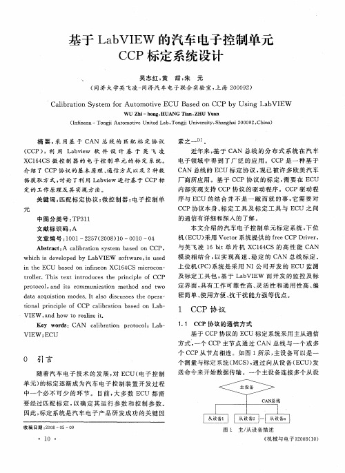
研究与开发电动汽车车载测试系统设计及应用曾莉莉温旭辉胡伟刘钧(中国科学院电工研究所,北京100080)摘要为了获得电动汽车电机驱动系统可靠性考核中需要的关键参数,本文提出了一中基于C A N总线的车载测试系统的设计,并详细介绍了系统硬件构成和软件设计,同时对C A N总线的实现和系统误差进行研究。
该系统能够同步采集模拟信号和C A N总线信号.而且该系统已经安装于北京121路公交车中的纯电动大客车上,连续无故障的运行了5个月,证明该系统具有高可靠性和强抗干扰能力。
关键词:电动汽车;车载测试系统;C A N总线T he D es i gn and A ppl i ca t i on of a V ehi cl e T es tSys t em f or El ect r i c V ehi c l esZ en g Li li W en X uhui H u W ei Li u J un(I nst i t ut e of E l ec t r i ca l E ngi neer i ng C hi nes e A ca de m y of Sci ences,B ei j i ng100080)A bs t r act I n order t o obt a i n key param et er s us ed t o as s ess t he r el i ab i l i t y of t he m ot or dri vi ngs ys t em f or el ect r i c ve hi cl e,t he des i gn of a vehi c l e t es t s ys t em bas ed on C A Nbus i s devel oped,and t he har dw ar e com ponent and s oft w ar e des i gn of t he s ys t em i S i nt r oduced,at t he sa m e t i m e,t hei m pl em ent at i on of t he C A N bus and s ys t em er r o r is s t udi e d.T hi s s ys t em can s ynchr o nous l y acqui reanal ogy si gna l and C A Nbus s i gnal.Fur t he rm ore t he s ys t em m ount e d on t he el e ct r i c vehi c l e ope r at i ng i n t he Bei j i ng bus l i n e121has t roubl e-f re e oper at ed f or f i v e m ont hs,w hi ch pr ov es t hi s s ys t em has hi g h r el i ab i l i t y and st r ong ant i-j am m i ng capabi l i t y.K ey w ords:el ect r i cal veh i cl es:a vehi c l e t es t s ys t em;CA N—b us1引言2电动汽车电机驱动系统简介随着能源和环境问题日益受到重视,电动汽车以其清洁无污染、能量效率高、低噪声、能源多样化等优点研究发展迅速。
摘要在当前全球汽车工业面临金融危机和能源环境问题的巨大挑战的情况下,发展电动汽车,利用无污染的绿色能源,实现汽车能源动力系统的电气化,推动传统汽车产业的战略转型,在国际上已经形成了广泛共识。
本课题以电动汽车他励电机控制器为例,以实现电动汽车的加、减速,起、制动等基本功能以及一些特殊情况下的处理。
以开发出高可靠性、高性能指标、低成本并且具有自主知识产权的电动汽车电机驱动控制系统为目的。
主要包括硬件电路板的设计,以及驱动系统的软件部分的仿真调试。
在驱动系统硬件设计中,这里主控制芯片采用ATMEL公司的ATmega64芯片。
功率模块采用多MOSFET并联的方式,有效的节约了成本。
电源模块采用基于UC3842的开关电源电路。
选用IR公司的IR2110作为驱动芯片,高端输出驱动电流可到1.9A,低端输出驱动电流可到2.3A,能够提供7个MOSFET并联时驱动电流。
对于电流检测模块,本文没有采用电流传感器或者是康铜丝,而是采用了一种基于MOSFET管压降的电流检测电路,这种方式即节约了成本也保证了检测精度。
驱动系统的软件设计中,主要实现的功能为:开关量的检测处理,故障检测,串口通讯,励磁、电枢控制,报警功能等。
针对他励电机电动汽车的控制特性,提出了节能控制算法和最大转矩控制算法,用于提高电动汽车的续航里程和加速性能。
他励直流电动机驱动系统能够很好的运行在电动汽车上,性能可靠、结构简单,并且节约了成本,使电动汽车的性价比大大提高,有利于电动汽车的普及。
关键词:电动汽车,ATmega64,他励直流电机,PID模糊控制目录摘要 (1)第一章绪论1.1纯电动汽车在国内的发展状况 (3)1.2 国外电动汽车发展现状 (3)1.3 本课题的任务和主要工作 (4)第二章他励电动机的控制理论基础2.1他励直流电动机的调速与制动 (5)2.1.1直流电动机电枢电动势和电磁转矩 (5)2.1.2 他励直流电动机的机械特性 (6)第三章系统的硬件设计3.1系统硬件的整体设计方案 (10)3.2主控制器MCU的介绍 (10)3.2.1 MCU的选择 (10)3.2.2 ATmega64的特性与内部结构 (11)3.3开关电源模块 (12)3.4电流检测模块 (13)3.5驱动电路的设计 (16)3.6电压检测电路 (17)3.7温度检测电路 (18)3.8加减速踏板信号检测电路 (19)3.9 开关量输入信号 (20)3.10蜂鸣器报警电路 (20)3.11通讯模块电路设计 (21)3.12硬件抗干扰的设计 (22)3.13本章小结 (23)第四章系统的软件设计4.1 电动汽车的控制策略研究 (24)4.1.1再生制动控制策略 (24)4.1.2驱动控制策略 (24)4.2 主要任务模块的详细设计 (26)4.2.1主程序 (26)4.2.2 励磁、电枢PWM控制模块 (27)4.2.3 电动机速度测量 (28)4.3 本章小结 (29)第五章总结 (30)参考文献 (31)第一章绪论1.1 纯电动汽车在国内的发展状况与世界其他国家一样,电动汽车研发工作在我国也正在如火如荼的进行着:“十五”期间,国家从维护我国能源安全、改善大气环境、提高汽车工业竞争力、实现我国汽车工业的跨越式发展的战略高度考虑,设立“电动汽车重大科技专项’’,通过组织企业、高等院校和科研机构,集中国家、地方、企业、高校、科研院所等方面的力量进行联合攻关。
插电式燃料电池轿车整车控制器仿真测试平台设计寇改红刘奋梁伟铭(上海汽车集团股份有限公司新能源汽车事业部,上海201804)=摘要> 利用M ATLAB/S i m u link实时仿真环境、dSPACE实时仿真系统、CAN通讯设备,系统地设计了插电式燃料电池轿车整车控制器的仿真测试平台。
该平台可以验证整车控制算法是否符合设计要求,并尽早发现软件的设计漏洞,为整车控制器的实车调试打下良好的基础。
=Abstract>B ased on the MATLAB/Si m ulink rea-l ti m e soft w are env ironm en,t dSPACE rea-l ti m e si m ulati o n syste m and C AN co mmunicati o n too ls,the si m ulati o n test platfor m of vehic le contro ller fo r plug-i n FCV is desi g ned.The platfor m can be used to verify w hether the contr o l algorithm s satisfy the desi g n require m en,t and to find t h e desi g n proble m s as soon as possi b l e and lay a so li d foundati o n fo r the latter debugg i n g on veh icle.=关键词> 插电式燃料电池轿车控制器do:i1013969/j1i s sn.1007-4554.2011.06.020引言在整车控制器的开发过程中,利用整车控制器硬件在环仿真测试平台构建虚拟的整车现场环境,对控制器进行硬件在环仿真测试,不但可以大大加快整车控制器软、硬件的开发进程,而且开发成功的控制器也具有较高的可靠性。