YL-62 壁障传感器使用说明
- 格式:pdf
- 大小:57.10 KB
- 文档页数:1

多参数传感器说明书-CAL-FENGHAI.-(YICAI)-Company One1在安装使用产品前应仔细阅读本使用说明书GD6矿用多参数传感器使用说明书执行标准:GB3836-2010、AQ6205-2006、AQ6211-2008、AQ1052-2008、MT381-2007、MT447-1995、Q/ZMDZ09-2011天津中煤电子信息工程有限公司2011年10月目录1、概述2、工作原理与外形结构3、主要技术性能及参数4、安装与使用5、故障分析与排除6、安全保护及注意事项7、保养与维修8、运输、贮存9、随机文件及附件10、其他1概述GD6矿用多参数传感器(以下简称“传感器”),是KJ86煤矿安全监控系统配套设备。
该产品是本公司自主开发的新一代智能型传感器,采用了目前最先进的CAN总线数据传输形式,集成了甲烷、一氧化碳、二氧化碳、氧气、温度和湿度为一体的监测。
用途传感器主要用于测量煤矿井下和避难硐室、救生舱环境中的甲烷、一氧化碳、二氧化碳、氧气气体浓度和温湿度情况,并可将测量到的数据转换成数字CAN总线数字信号通过干线上传到地面中心站计算机中进行分析处理﹑存储﹑显示,从而可实现地面对井下的监测。
特点该传感器采用低功耗可编程微处理器技术、贴片焊接工艺,配备了红外甲烷、二氧化碳;电化学一氧化碳、氧气和温湿度等传感元件,并配有相应的红外遥控设置功能。
具有坚固耐用﹑操作简单、使用方便﹑功耗低﹑性能稳定等特点。
型号传感器产品型号编制说明G D 66路多参数传感器工作环境条件环境温度:(0~40)℃相对湿度:≤95%(25℃)相对压力:(80~116)KPa无显着振动和冲击的场合;具有甲烷、煤尘等爆炸性混合物的危险场所使用。
防爆型式:矿用本质安全兼隔爆型;防爆标志:ExibdI关联和配接设备:见附录A。
2、工作原理及结构工作原理传感器的工作原理是以MicroChipPIC单片机为核心,对传感元件采集到的信号进行处理、分析、判断、显示。

The Pocket Series is equipped with a high-resolution 256 x 192 (49,152 pixels) detector,a high-resolution 8 MP optical lens, and a 3.5”LCD touch screen. It helps you locate faultsfaster and more efficiently, and measure temperatures more accurately. The wide tem-perature range of -20 °C to 400 °C is ideal for Building Inspections, HVAC, Electrical, andMechanical Equipment Maintenance. The 25 Hz frame rate allows for smooth operationand the Wi-Fi function allows the Pocket to share images in realtime. The Pocket Seriesputs a powerful thermography tool in your pocket so it’s always there when you need it.•Thermography :Device detects the real-time temperature, and display it on the screen•Storage :Device is equipped with memory card of 16 GB to store recorded captured snapshots, and important data.•Palette :Device supports 7 palettes.•Fusion :The camera can display both thermal image and real image at the same time•Vidéo :The camera is able to make videos with a storage capacity of 10 hours•Pocket format :The camera is compact enough to fit in your pocketKey features :•Thermal resolution: 256 x 192 (49, 152 pixels),•NETD : < 40 mK (@ 25°C, F# = 1.0)•Accurately measure temperature from -20°C to 400 °C(-4°F to 752°F)•Accuracy: Max. (± 2°C/3.6°F, ± 2%)•Thermal, fusion, PIP, and opticale modes,8 MP optical camera•25 Hz image frequency•Manual, automatic, and 1-Tap level and span•Up to 4 hours continuous running•High temperature alarm•LED work light• 1.0x to 4.0x continuous digital zoom•Built-in 16 GB memorySpecifications :Applications :High Performance Compact Thermography Camera for ProfessionalsPocket formatHot water pipes verification Electrical inspectionsHVACPCB Circuit BoardsImage modes :Fusion OpticalThermalPIPMultiple Level & Span modesThree level & Span modes (manual,automatic, and 1-Tap) help youinstantly improve image contrastand highlight potential problems.Portable pocket-sized DesignEasy to carry and hold. It fits per-fectly in your pocket and tool bag.Faster TroubleshootingBuilt-in speaker and flash light givethe operator audio and visual alertsto high temperatures. Full-screenmeasurement using different userpresets checks everywhere instantly.Rugged & Durable DesignIP54 rated for protection against water and dust.Featuring 2-meter drop protection, suitable forindustrial use.LED flashlightThe LED flashlightallows you to worksafely in dim or darkenvironmentsOn-Camera RecordingBuilt-in 16 GB internal memory pro-vides onboard recording and play-back.Mobile applicationConnect (Wi-Fi or Hotspot) to theSefram Viewer App for transmittingpictures from the camera to a mobi-le phone. Analyze, share images andgenerate simple reports in real-timeon-site.PC softwareUse the Sefram Analyzer PC softwa-re to provide customers with pro-fessional reports with images docu-menting problems and repairs.Quick StartGuide (x1)PowerSupply (x1)USB Cable (x1)Carrying Pouch (x1)Wrist Strap (x1)。

油传感器的说明书一、产品简介油传感器是一种用于检测、监测和测量车辆燃油量的装置。
本产品采用先进的传感技术,能准确、快捷地获取车辆燃油信息,并通过相关系统进行处理和反馈。
二、产品特点1. 高精度:本产品采用高精度传感器,能够准确测量车辆燃油量,并反映在仪表盘上,使驾驶员能够清晰了解车辆燃油储备情况。
2. 快速响应:油传感器具有快速响应的特点,能够在短时间内获取并传递的车辆燃油信息,及时提醒驾驶员进行加油或油量监测。
3. 安全可靠:产品的设计和制造采用严格的质量控制标准,确保产品的安全性和可靠性,有效防止因燃油量不足而引发的车辆故障或事故。
4. 耐用性强:油传感器采用优质材料制造,具有耐高温、耐压和耐腐蚀的特点,能够在各种恶劣环境下工作,确保产品的长期稳定运行。
5. 高兼容性:本产品兼容多个车辆品牌和型号,可以广泛应用于各类汽车、电动车、摩托车等交通工具中。
三、产品使用方法1. 安装:将油传感器正确安装在车辆燃油箱中,并固定好。
2. 连接电源:将油传感器与车辆电气系统连接,确保传感器能够获取当前燃油量信息,并将其传递给仪表盘等相关系统。
3. 使用:当启动车辆时,仪表盘将显示当前燃油量状态。
当燃油量接近警戒线时,仪表盘将发出警报提醒驾驶员及时加油。
四、产品注意事项1. 使用本产品前,请仔细阅读产品说明书,了解产品安装和使用方法。
2. 请确保油传感器安装正确,固定牢固,避免因安装不当造成的车辆故障。
3. 在使用过程中,如发现异常情况,请及时停止使用,并联系售后服务中心进行检修或更换。
4. 请按照产品规定的周期进行维护和保养,保持油传感器的正常工作状态。
5. 本产品不可拆卸,如需更换或维修,请联系售后服务中心进行处理。
五、售后服务本产品提供一年质保服务。
如在质保期内出现非人为损坏的功能问题,用户可联系售后服务中心进行维修或更换。
在质保期过后或因人为损坏引起的功能问题,用户可享受有偿维修服务。
六、结语我们的油传感器将为您提供准确、可靠的燃油信息,帮助您更好地管理和使用车辆。

色标传感器使用说明书产品部件说明:输出电路:NPN 型号PNP 型号安装方法:* 安装在DIN 轨道上1、将主机底部的卡槽与轨道对齐。
按箭头 1 的方向推动主机的同时使其往箭头 2 的方向倾斜。
2、拆卸传感器的方法是,在朝箭头 1 的方向推动主机的同时,朝箭头 3 的方向提升主机。
* 安装到墙壁上(仅适用于主模块)将模块放到选配的安装架上,将其安装到一起,并使用两个 M3 螺钉固定住,连接光纤模块1, 按箭头 1 所示的方向开启防尘盖。
2, 按箭头 2 所示的方向往下移光纤锁杆。
3, 将光纤模块记号上标记的长度插入光纤孔。
4, 按箭头 4 所示的方向往下移光纤锁杆。
5, 如果使用较薄的光纤模块,则需要使用随其提供的转接器。
6, 如果没有连接正确的转接器,则薄型光纤模块将不能正确地检测目标物。
(转接器随光纤模块提供。
)7, 若将同轴反光型光纤模块连接到放大器上,应将单芯光纤连接到发射器侧而将多芯光纤连接到接收器侧。
设置灵敏度* MARK 模式下两点校准:1,在光纤头前方没有放置任何工件时,按 SET(设置)按钮(按键时间不超过 2 秒).2,将一个工件放置在光纤前方,按 SET(设置)按钮(按键时间不超过 2 秒).两个步骤测出的数值以及 RGB 检测通道会显示在屏幕上并自动记忆储存.* C 或 CI 模式下的校准自学习:把光纤对准需要检测的颜色,按下一次 SET 就可以了,传感器会自动记录当前的颜色匹配值及光亮值,作为正常工作时的判断标准.MATK 是普通的色标检测模式,放大器会选择 RGB 通道中的一个作为判断通道。
C 模式时通用的颜色匹配检测模式,千分之一千表示颜色完全相同,一般认为千分之 900 就是一种颜色。
CI 是颜色+光亮值模式,用来精确检测物体的颜色以及物体的光亮值。
千分之 1000 表示完全相同。
C 模式下物体在光纤前面晃动也可以正常检测,CI 模式下,物体在光纤前面有任何晃动都会造成信号值急剧减小,从而传感器认为 CI 不匹配。

R智能型流动传感器使用说明书M-F L60/61-CN-V1.34. 针对较低流速,可选购方形低流量三通US0029。
见右图:拧紧,拧紧扭矩为1.5Nm。
6. 请选购伊玛合格的防爆线搭配本防爆产品,否则请勿使用。
7. 产品外壳所安装的管道须与等电位接电系统正确连结。
8. 警示语: 爆炸性环境存在时,请勿打开。
5. 安装防爆线时需使用扳手544. 传感器插入深度: 至少保证深度≥12mm, 使用转接头(需单独订货)可确保正确的深度。
注意:传感器探头不可碰到管壁。
5556当前流速过低空管闪烁提示(LED 0 闪烁)FL-黄色FE-灰色58 575960616264636566备注:标准探棒长度约45mm,另有加长型探棒长度 100型号mm/200mm,和防腐蚀型钛合金探棒供客户选购。
R智能型流动温度传感器使用说明书M-FL62-CN-V1.3674. 传感器插入深度: 至少保证深度≥12mm, 使用转接头(需单 注意:传感器探头不可碰到管壁独订货)可确保正确的深度。
70694. 针对较低流速,可选购方形 低流量三通US0029。
见右图:拧紧,拧紧扭矩为1.5Nm 。
6. 请选购伊玛合格的防爆线7. 产品外壳所安装的管道须与 等电位接电系统正确连结。
8. 警示语: 爆炸性环境存在时,请勿打开。
5. 安装防爆线时需使用扳手PNP/NPN输出PIN1: L+, 电源 (BN)PIN2流动PNP/NPN输出 (WH)PIN3L-(BU)PIN4温度PNP/NPN输出 (BK)PIN5P, 编程线 (RD):: , 电源::插件接脚定义72 71继电器及PNP输出模拟电流输出PIN1: L+, 电源 (BN)PIN2: 流动4-20mA输出 (WH)PIN3: L-, 电源 (BU)PIN4: 温度4-20mA输出 (BK)PIN5: P, 编程线 (RD)PIN1 (BN)PIN2(WH)PIN3(BU)PIN4(BK)PIN5(RD): L+, 电源: 流动继电器输出公共端: L-, 电源: 温度PNP/NPN输出: 流动继电器常开触点模拟量输出产品无显示开关点SP74737576(16)ASP:℃/-40℉~+284℉输出信号的测量值为4mA。
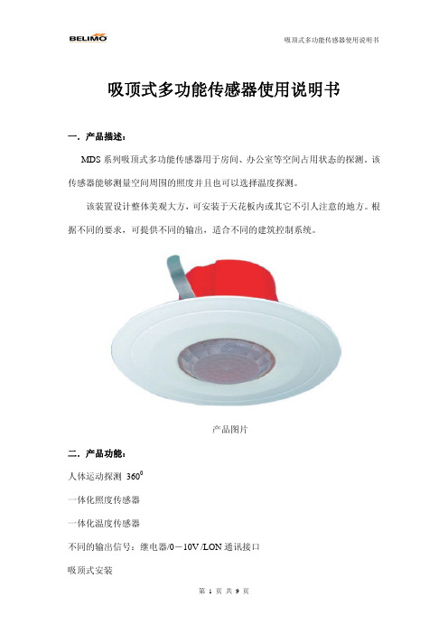
吸顶式多功能传感器使用说明书一.产品描述:MDS系列吸顶式多功能传感器用于房间、办公室等空间占用状态的探测。
该传感器能够测量空间周围的照度并且也可以选择温度探测。
该装置设计整体美观大方,可安装于天花板内或其它不引人注意的地方。
根据不同的要求,可提供不同的输出,适合不同的建筑控制系统。
产品图片二.产品功能:人体运动探测 3600一体化照度传感器一体化温度传感器不同的输出信号:继电器/0-10V /LON通讯接口吸顶式安装三.型号选择:型号产品类型描述EXT-TN-1066869 标准1 1.PIR-3600人体运动传感器,继电器输出2.照度传感器,0-10VEXT-TN-1072396 标准3 1.PIR-3600人体运动传感器,继电器输出2.照度传感器,0-10V3.温度传感器,0-10VEXT-TN-1071504 LON1 1.PIR-3600人体运动传感器,带LON输出2.照度传感器,LON FTT10接口四.技术参数:1.符合标准CE认证:-2004/108/EG 电磁认证-2001/95/EG 产品安全认证EN认证:-EN60730-1:2002电磁认证-EN60730-1:2002 产品安全认证2.基本数据:电源:DC2-24V / AC24V(±10%)接线端子:旋转式接线端子,最大1.5mm2运动传感器:4元PIR “被动红外”,通过内部LED灯显示有效探测人体运动照度传感器:0-1kLux,光电二极管带绿光过滤器精度:一般±50Lux温度传感器:0-50℃精度:一般±0.5K外盒背部:材质ABS,橙色外盒前部:材质ABS,纯白防护等级:IP20通过EN60529认证工作环境温度:0-50℃运输:-10~50℃,最大湿度:85%RH,无冷凝水重量:80g3.标准1传感器:电源消耗:一般0.6W/1.5V A模拟输出(照度):0-10V,最大10mA继电器输出(人体运动):无源触点最大24V/1A ,运动探测器可设定延时时间为1sec~30min4.标准3传感器:电源消耗:一般0.6W/1.5V A模拟输出(照度):0-10V,最大10mA模拟输出(温度):0-10V,最大10mA继电器输出(人体运动):无源触点最大24V/1A ,运动探测器可设定延时时间为1sec~30min5. LON1传感器:电源消耗:一般0.6W/4.2V ALON接口:FTT10,自由拓扑五.探测范围:典型探测范围一般探测范围1.典型测量角度:0-105度2.测量直径:D~3m,D~5m,D~7m3.测量直径D与安装高度H计算:Max.D=2.7*H 六.严重警告本装置的安装与使用必须由专业技术人员进行操作,如不遵守有关要求,直接或间接的可能导致死亡或严重的人身伤害!七.安装注意事项1.安装高度:安装高度对运动传感器探测面积有一个直接的影响;最适宜的安装高度为2.7米;所有的偏离测量将导致探测面积的改变。
4路循迹传感器模块使用说明 一模块描述此模块是为智能小车 、 机器人等自动化机械装置提供一种多用途的红外线探测系统的解决方案 。
该传感器模块对环境光线适应能力强 , 其具有一对红外线发射与接收管 , 发射管发射出一定频率的红外线 , 当检测方向遇到障碍物 ( 反射面)时 , 红外线反射回来被接收管接收 , 经过比较器电路处理之后 , 同时信号输出接口输出数字信号(一个低电平信号) ,可通过电位器旋钮调节检测距离,有效距离范围2 ~ 6 0cm ,工作电压为3.3V-5V 。
该传感器的探测距离可以通过电位器调节、具有干扰小、便于装配、使用方便等特点,可以广泛应用于机器人避障 、 避障小车、流水线计数及黑白线循迹等众多场合。
二模块参数说明1当模块检测到前方障碍物信号时,电路板上红色指示灯点亮,同时OUT端口持续输出低电平信号 , 该模块检测距离2~60cm, 检测角度35 °, 检测距离可以通过电位器进行调节,顺时针调电位器,检测距离增加;逆时针调电位器 , 检测距离减少。
2 、传感器 属于 红外线反射探测 , 因此目标的反射率和形状是探测距离的关键 。
其中黑色探测距离最小 , 白色最大 ; 小面积物体距离小 , 大面积距离大。
3 、 传感器模块输出端口OUT可直接与单片机IO口连接即可, 也可以直接驱动一个5V继电器模块或者蜂鸣器模块;连接方式: VCC-VCC;GND-GND;OUT-IO4 、比较器 采用LM3 39 ,工作稳定;5 、可采用3 .3V -5V直流电源对模块进行供电。
当电源接通时,绿色电源指示灯点亮;6 、具有3mm的螺丝孔,便于固定、安装;7 、尺寸大小:中控板42mm × 38mm×12mm (长 ×宽×高)小板25mm ×12mm×12mm(长×宽 ×高)8 、 每个模块在发货已经将阈值比较电压通过电位器调节好,买家也可以根据实际情况进行调节(提示:模块反射距离越大,越容易误触发)三模块接口说明( 16线制)红外探头VCCGNDOUT对应接入中控板VCCGNDINx中控板供电 : 模块6p排针接口处V CC外接3.3V-5V电压 (可以直接与5v单片机和3.3v单片机相连 ) ; GND外接GND;OUT1-OUT4接单片机IO口四模块测试说明测试探头:移开探头前面所有物体,且探头不要指向有阳光的地方(光线对探头有较大干扰) ,将探头板接上电源后用万用表测量OUT和GND之间的电压,正常范围应该在0.6v-2.5v之间,用白纸挡在探头前,用万用表测量OUT和GND 之间的电压,正常范围应该接近0V.简单的说,就是用白纸挡住探头后,OUT和GND之间的电压会有一个明显的降低,这样就算正常。
MODEL 061/063 TEMPERATURE SENSOR OPERATION MANUAL Document No 061-9800061/063 TEMPERATURE SENSORSOPERATION MANUAL1.0 GENERAL INFORMATION1.1 Models 061 and 063 are precision thermistor temperature sensors. For the mostaccurate air temperature measurements, the sensors are always mounted in aradiation shield, which minimizes errors caused by solar and terrestrial radiationheating. Sensors produce resistance change inversely proportional to temperature.Model 061 is designed for air temperature measurement. The Model 061 has a time constant of only 10 seconds.Model 063 is designed for the direct measurement of air, soil, and watertemperature. The 063 sensor is completely sealed in stainless steel housing, filledwith silicone oil. The Model 063 has a time constant of 60 seconds.1.2 Sensor Cable and ConnectionsAll sensors are supplied with signal leads one foot in length. Dependent onparticular applications, longer cable length and cable connectors may be provided as an option.2.0 INSTALLATION2.1 Temperature Sensor InstallationA. AIR TEMPERATUREFor maximum accuracy, it is desirable to mount the temperature sensor in a radiation shield. The radiation shield will minimize effects of solar and terrestrial radiation and will additionally provide adequate air flow over the sensor. Mechanical mountinginformation is given in the radiation shield manual.B. SOIL TEMPERATUREThe Model 063 is used for soil temperature measurements. Installation of the soiltemperature probe requires the digging of a small hole to the required measurement depth in firm, undisturbed soil. The probe is inserted horizontally into this firm soil,and the soil is replaced in the hole and packed firmly.C. WATER TEMPERATUREThe Model 063 Temperature Sensor should be placed in water, free from heatradiation sources.D. These sensors are durable, field proven devices; however,DO NOT DROP OR EXPOSE THE SENSOR TO HEAVY SHOCK2.2 Wiring ConnectionsThe output of the thermistor sensor is a relatively high resistance that variesaccording to temperature. It is important not to introduce any parallel resistancepaths. A parallel resistance path may be established by a dirt/moisture build-upbetween two sensor leads. This may occur in poorly made splices and unprotected connections. It is advisable to always use a protective coating on exposed sensor connections. Use a coating such as silastic rubber (RTV).2.3 Direct Wiring to a Met One Instruments TranslatorWhen the sensor is connected directly to a Met One Instruments Translator Module the sensor is loaded with the appropriate resistor to provide a linear output.2.4 Direct Connection to a Data LoggerWhen the sensor is connected to a data logger the data logger must have aterminating resistor to provide a linear output. Refer to Figure 2-1.3.0 OPERATIONAL CHECK-OUT AND CALIBRATION3.1 Temperature Sensor Check-outCompare sensor readings against a precision mercury thermometer. Use a LoCurrent Digital Ohmmeter and compare readings of temperature vs. resistance. 4.0 MAINTENANCE AND TROUBLESHOOTING4.1 General Maintenance Schedule*6 – 12 Month Intervals:A. Inspect sensor for proper operation per Section 3.1.*Schedule is based on average to adverse environments.4.2 Troubleshooting ProceduresA. Incorrect sensor signal: check sensor input connections: check temperature vs.sensor output signal using Table 3-1. Verify that the sensor has the correctterminating resistor if not used with a Met One Translator.4.3 Temperature Sensor CalibrationThe sensors are tested for calibration conformity at the factory. Field calibration may be verified by testing and sensors against themselves or against a known standard.It is not possible to make alterations to the sensor’s c alibration, as it is fixed.4.4 Ice Bath (0︒C Calibration Test)This calibration test requires that a practical reference point of 0︒C be obtained by the preparation of a mixture of shaved or finely cracked ice and enough water to coverbut not float the ice. To create a precision ice bath (± 0.002︒C), distilled water mustbe used for the bath and to make the ice. This mixture is made and contained in alarge wide-mouth Dewar flask with a capacity of about one quart or more. The Dewar flask is stopped up with a cork or other suitable material, with two holes provided for the insertion of both the temperature and a glass thermometer. Both the probe andthermometer are inserted into the Dewar flask so that the tips of each are at least 4 ½ inches below the surface of the mixture, ½ inch from the sides of the Dewar with aminimum of one inch remaining below. Using a precision volt-ohmmeter: measurethe resistance vs. temperature as given in Table 3-1.061063-3Figure 2-1Connections of 061/063 Temperature SensorTo DataloggerTEMP DEG C RCAL TEMP DEG C RCAL0 20516 51 46491 19612 52 45472 18774 53 44483 17996 54 43524 17271 55 42585 16593 56 41666 15960 57 40767 15365 58 39898 14806 59 39039 14280 60 382010 13784 61 373911 13315 62 365912 12872 63 358113 12451 64 350514 12052 65 343115 11673 66 335816 11312 67 328717 10969 68 321818 10641 69 315019 10328 70 308320 10029 71 301821 9743 72 295422 9469 73 289123 9206 74 283024 8954 75 276925 8712 76 271026 8479 77 265327 8256 78 259628 8041 79 254029 7833 80 248630 7633 81 243231 7441 82 238032 7255 83 232833 7075 84 227834 6902 85 222835 6734 86 217936 6572 87 213137 6415 88 208438 6263 89 203839 6115 90 199240 5973 91 194841 5834 92 190442 5700 93 186143 5569 94 181844 5443 95 177645 5320 96 173546 5200 97 169547 5084 98 165548 4970 99 161649 4860 100 157850 4753*VALUE WITH 3200 OHM RESISTOR IN PARALLEL WITH SENSORRANGE 0︒C TO 100︒CTHERMISTOR BEAD 44201TEMP DEG F RCAL TEMP DEG F RCAL32 20516 84 785633 20005 85 774434 19516 86 763335 19047 87 752636 18596 88 742037 18164 89 731638 17748 90 721439 17349 91 711540 16964 92 701741 16593 93 692142 16236 94 682743 15892 95 673444 15559 96 664345 15238 97 655446 14928 98 646747 14627 99 638148 14337 100 629649 14056 101 621350 13784 102 613251 13520 103 605152 13265 104 597353 13017 105 589554 12776 106 581955 12543 107 574456 12316 108 567057 12095 109 559858 11881 110 552759 11673 111 545660 11470 112 538761 11273 113 532062 11081 114 525363 10894 115 518764 10712 116 512265 10535 117 505866 10362 118 499567 10193 119 493368 10029 120 487369 9868 121 481270 9712 122 475371 9559 123 469572 9409 124 463873 9263 125 458174 9121 126 452575 8981 127 447076 8845 128 441677 8712 129 436278 8582 130 431079 8454 131 425880 8329 132 420681 8207 133 415682 8088 134 410683 7971 135 4057*VALUE WITH 3200 OHM RESISTOR IN PARALLEL WITH SENSORRANGE 32︒F TO 212︒FTHERMISTOR BEAD 44201Table 3-1B (continued)Model 063-2 RESISTANCE CHART DEG FTEMP DEG F RCAL TEMP DEG F RCAL136 4008 178 2426137 3960 179 2397138 3913 180 2368139 3866 181 2340140 3820 182 2311141 3775 183 2283142 3730 184 2255143 3685 185 2228144 3642 186 2201145 3599 187 2174146 3556 188 2147147 3514 189 2121148 3472 190 2094149 3431 191 2069150 3390 192 2043151 3350 193 2018152 3311 194 1992153 3272 195 1967154 3233 196 1943155 3195 197 1918156 3157 198 1894157 3120 199 1870158 3083 200 1846159 3046 201 1823160 3010 202 1800161 2975 203 1776162 2940 204 1754163 2905 205 1731164 2870 206 1708165 2836 207 1686166 2803 208 1664167 2769 209 1642168 2737 210 1621169 2704 211 1599170 2672 212 1578171 2640172 2608173 2577174 2547175 2516176 2486177 2456*VALUE WITH 3200 OHM RESISTOR IN PARALLEL WITH SENSORRANGE 32︒F TO 212︒FTHERMISTOR BEAD 44201For RCAL: Where: Tc = Temp (deg C) Tc = ((((Rt ‾1) + 3200 ‾1)) ‾1 – 2768.23) ∕-17.115 RT = RCALRt = ((((-17.115Tc) + 2768.23) ‾1) – (3200) ‾1) ‾1Table 3-1CModel 061, 063-3 RESISTANCE CHART DEG C TEMP DEG C RCAL TEMP DEG C RCAL -30 110236 10 26155 -29 104464 11 25436 -28 99187 12 24739 -27 94344 13 24064 -26 89882 14 23409 -25 85760 15 22775 -24 81939 16 22159 -23 78388 17 21561 -22 75079 18 20980 -21 71988 19 20416 -20 69094 20 19868 -19 66379 21 19335 -18 63827 22 18816 -17 61424 23 18311 -16 59157 24 17820 -15 57014 25 17342 -14 54986 26 16876 -13 53064 27 16421 -12 51240 28 15979 -11 49506 29 15547 -10 47856 30 15126 -9 46284 31 14715 -8 44785 32 14314 -7 43353 33 13923 -6 41985 34 13541 -5 40675 35 13167 -4 39421 36 12802 -3 38218 37 12446 -2 37065 38 12097 -1 35957 39 117560 34892 40 114231 33868 41 110972 32883 42 107773 31934 43 104654 31019 44 101595 30136 45 98596 29284 46 95667 28462 47 92798 27667 48 89979 26899 50 8450*VALUE WITH 18.7K RESISTOR IN PARALLEL WITH SENSORRANGE –30︒C TO +50︒CTHERMISTOR BEAD 44203Table 3-1DModel 061, 063-3 RESISTANCE CHART DEG FTEMP DEG F RCAL TEMP DEG F RCAL -22 110236 33 34319-21 106964 34 33757-20 103855 35 33207-19 100895 36 32669-18 98075 37 32141-17 95385 38 31625-16 92816 39 31119-15 90361 40 30622-14 88011 41 30136-13 85760 42 29659-12 83602 43 29192-11 81532 44 28733-10 79543 45 28283-9 77632 46 27841-8 75794 47 27408-7 74025 48 26983-6 72321 49 26565-5 70678 50 26155-4 69094 51 25753-3 67565 52 25357-2 66088 53 24969-1 64661 54 245870 63281 55 242121 61946 56 238432 60654 57 234813 59402 58 231254 58190 59 227755 57014 60 224306 55874 61 220917 54768 62 217588 53694 63 214309 52651 64 2110810 51637 65 2079011 50652 66 2047812 49695 67 2017013 48763 68 1986814 47856 69 1957015 46974 70 1927616 46114 71 1898717 45277 72 1870318 44461 73 1842219 43666 74 1814620 42890 75 1787421 42134 76 1760622 41395 77 1734223 40675 78 1708124 39972 79 1682525 39285 80 1657226 38614 81 1632227 37958 82 1607628 37317 83 1583429 36691 84 1559530 36078 85 1535931 35479 86 1512632 34892 87 14897Table 3-1D (Continued)Model 061, 063-3 RESISTANCE CHART DEG FTEMP DEG F RCAL TEMP DEG F RCAL88 14670 106 1106189 14447 107 1088390 14227 108 1070791 14009 109 1053492 13794 110 1036293 13583 111 1019394 13374 112 1002595 13167 113 985996 12963 114 969697 12762 115 953498 12564 116 937499 12368 117 9215 100 12174 118 9059 101 11983 119 8904 102 11794 120 8751 103 11607 121 8600 104 11423 122 8450 105 11241*VALUE WITH 18.7K RESISTOR IN PARALLEL WITH SENSORRANGE -22˚F TO +122˚FTERMISTOR BEAD 44203Tc= -(R*18700/(18700+R)-12175)/127.096Rt = -(127.096*Tc-12175)*18700/(127.096*Tc-12175+18700)。
传感器模块使用说明
壁障传感器模块使用说明
壁障
一模块描述
该传感器模块对环境光线适应能力强,其具有一对红外线发射与接收管,发射管发射出一定频率的红外线,当检测方向遇到障碍物(反射面)时,红外线反射回来被接收管接收,经过比较器电路处理之后,绿色指示灯会亮起,同时信号输出接口输出数字信号(一个低电平信号),可通过电位器旋钮调节检测距离,有效距离范围2~80cm,工作电压为3.3V-5V。
该传感器的探测距离可以通过电位器调节、具有干扰小、便于装配、使用方便等特点,可以广泛应用于机器人避障、避障小车、流水线计数及黑白线循迹等众多场合。
二模块参数说明
1当模块检测到前方障碍物信号时,电路板上绿色指示灯点亮电平,同时OUT端口持续输出低电平信号,该模块检测距离2~80cm,检测角度35°,检测距离可以通过电位器进行调节,顺时针调电位器,检测距离增加;逆时针调电位器,检测距离减少。
2、传感器主动红外线反射探测,因此目标的反射率和形状是探测距离的关键。
其中黑色探测距离最小,白色最大;小面积物体距离小,大面积距离大。
3、传感器模块输出端口OUT可直接与单片机IO口连接即可,也可以直接驱动一个5V继电器;连接方式:VCC-VCC;GND-GND;OUT-IO
4、比较器采用LM393,工作稳定;
5、可采用3-5V直流电源对模块进行供电。
当电源接通时,红色电源指示灯点亮;
6、具有3mm的螺丝孔,便于固定、安装;
7、电路板尺寸:3.1CM*1.5CM
8、每个模块在发货已经将阈值比较电压通过电位器调节好,非特殊情况,请勿随意调节电位器。
模块接口说明(33线制)
三模块接口说明(
1VCC外接3.3V-5V电压(可以直接与5v单片机和3.3v单片机相连)
2GND外接GND
3OUT小板数字量输出接口(0和1)。