螺旋槽止推气体轴承承载能力的数值分析
- 格式:pdf
- 大小:590.19 KB
- 文档页数:5
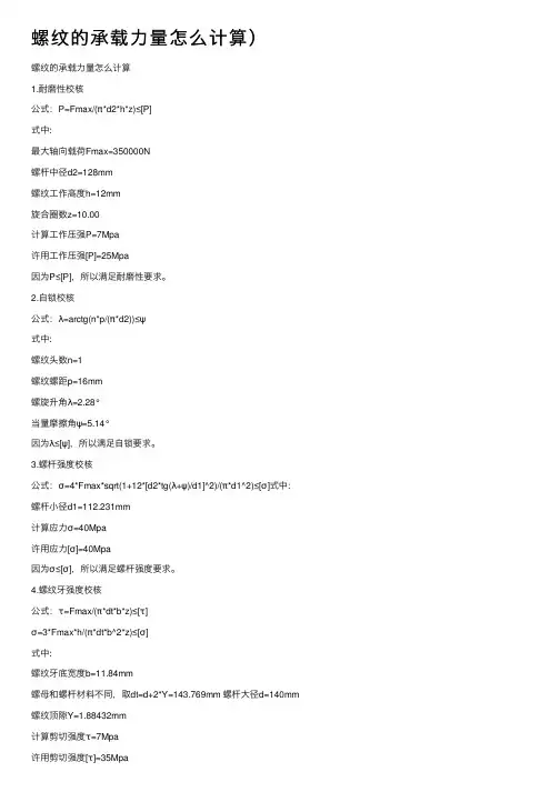
螺纹的承载⼒量怎么计算)螺纹的承载⼒量怎么计算1.耐磨性校核公式:P=Fmax/(π*d2*h*z)≤[P]式中:最⼤轴向载荷Fmax=350000N螺杆中径d2=128mm螺纹⼯作⾼度h=12mm旋合圈数z=10.00计算⼯作压强P=7Mpa许⽤⼯作压强[P]=25Mpa因为P≤[P],所以满⾜耐磨性要求。
2.⾃锁校核公式:λ=arctg(n*p/(π*d2))≤ψ式中:螺纹头数n=1螺纹螺距p=16mm螺旋升⾓λ=2.28°当量摩擦⾓ψ=5.14°因为λ≤[ψ],所以满⾜⾃锁要求。
3.螺杆强度校核公式:σ=4*Fmax*sqrt(1+12*[d2*tg(λ+ψ)/d1]^2)/(π*d1^2)≤[σ]式中:螺杆⼩径d1=112.231mm计算应⼒σ=40Mpa许⽤应⼒[σ]=40Mpa因为σ≤[σ],所以满⾜螺杆强度要求。
4.螺纹⽛强度校核公式:τ=Fmax/(π*dt*b*z)≤[τ]σ=3*Fmax*h/(π*dt*b^2*z)≤[σ]式中:螺纹⽛底宽度b=11.84mm螺母和螺杆材料不同,取dt=d+2*Y=143.769mm 螺杆⼤径d=140mm 螺纹顶隙Y=1.88432mm计算剪切强度τ=7Mpa许⽤剪切强度[τ]=35Mpa计算弯曲强度σ=20Mpa许⽤弯曲强度[σ]=45Mpa因为τ≤[τ]且σ≤[σ],所以满⾜螺纹⽛强度要求。
5.螺杆稳定性校核公式:Scr=20600*π^3*d1^4/(64*Fmax*(µ*l)^2)〉Sc 式中:螺杆长度系数µ=0.7螺杆⼯作长度l=300mm稳定性计算安全系数Scr=102.59稳定性安全系数Sc=3.8因为Scr〉Sc,所以满⾜稳定性要求。
轴承轴向承力极限摘要:1.轴承轴向承载能力的概念2.深沟球轴承的轴向承载能力3.圆柱滚子轴承的轴向承载能力4.圆锥滚子轴承的轴向承载能力5.轴承轴向承载能力的计算方法正文:一、轴承轴向承载能力的概念轴承轴向承载能力是指轴承在承受轴向负荷时,能够承受的最大负荷。
轴承在实际应用中,往往会受到来自各个方向的力,其中包括轴向力和径向力。
轴承的轴向承载能力直接影响到轴承的使用寿命和性能。
二、深沟球轴承的轴向承载能力深沟球轴承是最常见的一种轴承类型,其轴向承载能力主要取决于其内部结构和材料。
一般来说,深沟球轴承的轴向承载能力不应超过0.5c0 的值,其中c0 是轴承的基本径向间隙。
对于小型轴承(内径约在12 毫米以内)和轻型系列轴承(直径系列8、9、0 和1),其轴向承载能力不应超过0.25c0 的值。
三、圆柱滚子轴承的轴向承载能力圆柱滚子轴承的轴向承载能力通常较弱,因为其滚子在承受轴向负荷时容易产生非正常应力。
为了保证轴承的使用寿命和性能,圆柱滚子轴承在实际应用中不应承受轴向负荷。
四、圆锥滚子轴承的轴向承载能力圆锥滚子轴承的轴向承载能力较强,其内部结构和材料可以承受较大的轴向负荷。
不过,在承受轴向负荷时,圆锥滚子轴承的滚动体和滚针需要保持正确的平行中心线,以避免产生非正常应力。
五、轴承轴向承载能力的计算方法计算轴承轴向承载能力需要考虑轴承的材料、尺寸、内部结构等因素。
通常采用实验公式进行计算,例如深沟球轴承的轴向承载能力计算公式为:fap(k1c010000)/n(dd)-k2fr,其中fap 为轴承的轴向负荷,k1、k2 为材料系数,c0 为基本径向间隙,n 为转速,dd 为轴承的直径,fr 为滚道角。
总之,轴承轴向承载能力是轴承在承受轴向负荷时的关键性能指标。
标准滚动轴承承载能力计算在跟踪架通用轴系中,标准滚动轴承是重要的部件,轴承的承载能力计算是轴系设计中的关键问题。
采用通用轴系后,地平式跟踪架水平轴两端的轴承主要承受径向载荷,同时承受一定量的轴向载荷。
垂直轴上的轴承要承载垂直轴及上部转体的负荷,载荷较大;另一方面垂直轴为了满足强度和刚度的要求,轴径一般较大,轴承的尺寸与轴要相互配合,因此使用时必须考虑轴承的尺寸和轴向承载能力。
同时为了减少跟踪架的成本,尽量采用轴承厂批量生产的轴承。
角接触球轴承按公称接触角分为15°、25°、40°三种类型,公称接触角越大,轴向承载能力越强。
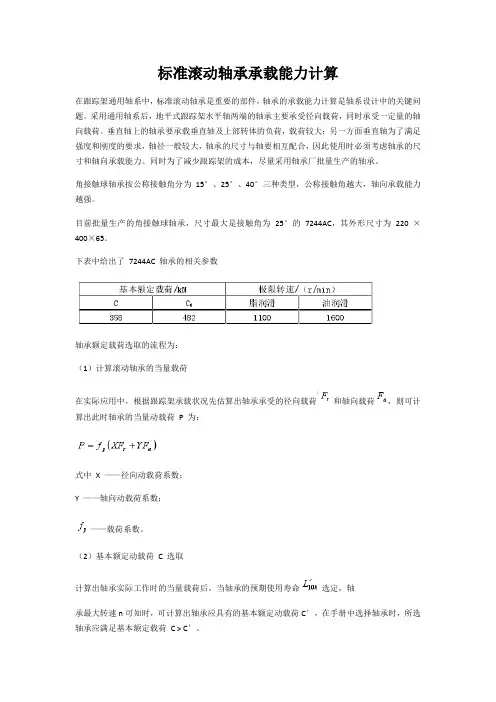
目前批量生产的角接触球轴承,尺寸最大是接触角为25°的7244AC,其外形尺寸为220 ×400×65。
下表中给出了7244AC 轴承的相关参数轴承额定载荷选取的流程为:(1)计算滚动轴承的当量载荷在实际应用中,根据跟踪架承载状况先估算出轴承承受的径向载荷和轴向载荷,则可计算出此时轴承的当量动载荷P 为:式中X ——径向动载荷系数;Y ——轴向动载荷系数;——载荷系数。
(2)基本额定动载荷 C 选取计算出轴承实际工作时的当量载荷后,当轴承的预期使用寿命选定,轴承最大转速n可知时,可计算出轴承应具有的基本额定动载荷C′,在手册中选择轴承时,所选轴承应满足基本额定载荷 C > C′。
式中——温度系数,可从机械设计手册中查得;ε——寿命指数,球轴承取3,滚子轴承取10/3。
由于角接触轴承的径向承载能力大于轴向承载能力,而其在垂直轴上的应用主要承受较大轴向载荷,因此必须考虑其轴向承载能力。
(3)轴承受轴向载荷时承载能力分析在轴承转速不高时,可以忽略钢球离心力和陀螺力矩的影响,钢球与内外套圈的接触角相等。
由赫兹接触理论得到轴承滚动体与内外滚道的接触变形和负荷之间的相互关系,可以表示为式中—滚动体与内外滚道接触变形总量;K —系数;Q —滚动体承受载荷;t —指数,线接触时为0.9,点接触时为2/3。
螺栓承压承载力设计值螺栓是一种常用于机械连接的紧固元件,在机械设计中扮演着十分重要的角色。
螺栓的承压承载力设计值是指在特定条件下螺栓能够承受的最大载荷,是螺栓设计过程中必须要考虑的重要参数之一。
本文将对螺栓承压承载力设计值进行详细阐述,包括承压承载力设计值的计算、影响因素以及相关的标准规范要求,以期对相关领域的工程师和设计者有所帮助。
一、螺栓承压承载力设计值的计算螺栓的承压承载力设计值是指在一定条件下,螺栓能够承受的最大静态或疲劳载荷。
静态承载力是指在螺栓材料破坏前,螺栓能够承受的最大载荷;而疲劳承载力是指螺栓在长期交变载荷下的承载能力。
一般来说,螺栓的承压承载力设计值可以通过以下公式计算得出:P = σn*AP为螺栓的承载力设计值,单位为牛顿(N)或千克力(kgf);σn为螺栓的许用应力,单位为牛顿/平方毫米(N/mm^2)或兆帕(MPa);A为螺栓截面积,单位为平方毫米(mm^2)。
许用应力σn通常是根据螺栓的材料和工作条件来确定的,常见的螺栓材料有碳钢、合金钢等。
二、影响螺栓承压承载力设计值的因素1. 螺栓材料:不同的螺栓材料具有不同的力学性能,如强度、延伸性等,这将直接影响螺栓的承载能力。
2. 螺纹型式:螺纹型式的选择将影响螺栓的连接强度和应力分布情况,进而影响承压承载力设计值。
3. 螺栓的预紧力:螺栓在安装时的预紧力将对其承压承载力设计值产生影响,通常预紧力越大,承载力设计值也越大。
4. 螺栓松动和腐蚀:螺栓松动和腐蚀会降低其承载能力,因此需要在设计中考虑螺栓的使用环境和防腐措施。
三、相关的标准规范要求在实际工程设计中,螺栓承压承载力设计值的确定需要遵循相关的标准规范要求,以确保螺栓的安全可靠。
国际上常用的螺栓设计规范有ISO898-1、ISO898-2等,国内则主要参考GB/T5782-2000《六角头螺栓》和GB/T3098.1-2000《六角头螺栓和螺母》等。
这些标准规范中都对螺栓的承载能力设计值的计算方法和计算公式进行了详细规定,同时也对螺栓的材料、尺寸、牙型等提出了要求。
轴承基本额定静载荷轴承是机械设备中最常见的部件之一,它可以帮助机械设备在高速运转时支撑起重量并减少摩擦力。
在选择轴承时,额定静载荷是一个非常重要的参数,本文将详细介绍轴承基本额定静载荷。
一、什么是额定静载荷?额定静载荷是指在理论上,轴承可以承受的最大静态负荷。
这意味着当轴承停止运转时,它能够支撑的最大负荷。
额定静载荷通常以牛顿(N)或磅力(lb)为单位表示。
二、为什么额定静载荷很重要?了解轴承的额定静载荷非常重要,因为它可以帮助我们确定哪种类型的轴承适合我们的应用。
如果我们使用的轴承不能够支撑所需的负载,那么它们可能会损坏或过早失效。
此外,如果我们使用超过额定静载荷的负载,则会导致严重的机器故障。
三、如何计算额定静载荷?计算轴承基本额定静载荷需要考虑多个因素,包括轴承的尺寸、材料和制造工艺等。
通常,轴承制造商会提供额定静载荷的公式和计算方法。
以下是一些常见的公式:1. 球面滚子轴承基本额定静载荷C0 = 0.6 × (d/D)0.67 × (1000/P)0.5其中,C0为额定静载荷(N),d为内径(mm),D为外径(mm),P为轴承宽度(mm)。
2. 圆锥滚子轴承基本额定静载荷C0 = 0.4 × (d/D)1/3 × (1000/P)其中,C0为额定静载荷(N),d为内径(mm),D为外径(mm),P为轴承宽度(mm)。
3. 滑动轴承基本额定静载荷C0 = P × b其中,C0为额定静载荷(N),P为压力(MPa),b为滑动面的长度(m)。
四、如何选择正确的轴承?选择正确的轴承需要考虑多个因素,包括负载类型、转速、环境条件和应用要求等。
以下是一些选择正确轴承的建议:1. 确定所需负载:根据应用的负载类型和大小,选择具有适当额定静载荷的轴承。
2. 确定所需转速:根据应用的转速,选择具有适当额定转速的轴承。
3. 确定环境条件:考虑环境因素,如温度、湿度和腐蚀性等,选择具有适当材料和润滑剂的轴承。
轴承轴向承力极限(实用版)目录1.轴承轴向承载能力的概念2.深沟球轴承的轴向承载能力3.圆柱滚子轴承的轴向承载能力4.圆锥滚子轴承的轴向承载能力5.轴承轴向承载能力的计算方法正文一、轴承轴向承载能力的概念轴承轴向承载能力是指轴承在轴向方向上能够承受的最大负荷。
在机械传动系统中,轴承是支撑轴的重要部件,其轴向承载能力直接影响到设备的运行稳定性和寿命。
二、深沟球轴承的轴向承载能力深沟球轴承是最常见的一类轴承,其在单纯的轴向负荷下,轴向负荷一般不应超过 0.5c0 的值。
其中,c0 表示轴承的基本径向尺寸。
对于小型轴承(内径约在 12 毫米以内)和轻型系列轴承(直径系列 8、9、0 和1),其轴向负荷不应超过 0.25c0 的值。
过大的轴向负荷会大大缩短轴承的使用寿命。
三、圆柱滚子轴承的轴向承载能力圆柱滚子轴承的轴向承载能力可以通过以下实验公式进行估算:fap(k1c010000)/n(dd)-k2fr。
其中,fap 表示轴承的轴向承载力;k1、k2 分别为轴承的滚子端面和挡边的安全系数;c0 为轴承的基本径向尺寸;n 为滚子数量;dd 为滚道直径;fr 为滚子材料的抗拉强度。
四、圆锥滚子轴承的轴向承载能力圆锥滚子轴承的滚动体是锥形滚轴,其轴向承载能力较圆柱滚子轴承大。
在承受轴向负荷时,圆锥滚子轴承的滚动体与滚道之间的角度较小,能够降低边缘应力集中,提高轴承的使用寿命。
五、轴承轴向承载能力的计算方法在实际应用中,轴承轴向承载能力的计算需要综合考虑轴承的类型、尺寸、材料等因素。
计算时通常采用经验公式或实验数据进行估算,以确保轴承在承受轴向负荷时能够正常工作,避免因负荷过大而导致轴承损坏。
综上所述,轴承轴向承载能力是衡量轴承在轴向方向上承受负荷的重要指标。
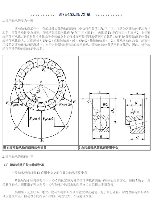
1.滚动轴承的受力分析滚动轴承在工作中,在通过轴心线的轴向载荷(中心轴向载荷)Fa作用下,可认为各滚动体平均分担载荷,即各滚动体受力相等。
当轴承在纯径向载荷Fr作用下(图6),内圈沿Fr方向移动一距离δ0,上半圈滚动体不承载,下半圈各滚动体由于个接触点上的弹性变形量不同承受不同的载荷,处于Fr作用线最下位置的滚动体承载最大,其值近似为5Fr/Z(点接触轴承)或4.6Fr/Z(线接触轴承),Z为轴承滚动体总数,远离作用线的各滚动体承载逐渐减小。
对于内外圈相对转动的滚动轴承,滚动体的位置是不断变化的,因此,每个滚动体所受的径向载荷是变载荷。
图6滚动轴承径向载荷的分析图7角接触轴承的载荷作用中心2.滚动轴承的载荷计算(1)滚动轴承的径向载荷计算一般轴承径向载荷Fr作用中心O的位置为轴承宽度中点。
角接触轴承径向载荷作用中心O的位置应为各滚动体的载荷矢量与轴中心线的交点,如图7所示。
角接触球轴承、圆锥滚子轴承载荷中心与轴承外侧端面的距离a可由直接从手册查得。
接触角α及直径D,越大,载荷作用中心距轴承宽度中点越远。
为了简化计算,常假设载荷中心就在轴承宽度中点,但这对于跨距较小的轴,误差较大,不宜随便简化。
图8角接触轴承受径向载荷产生附加轴向力1)滚动轴承的轴向载荷计算当作用于轴系上的轴向工作合力为FA,则轴系中受FA作用的轴承的轴向载荷Fa=FA,不受FA作用的轴承的轴向载荷Fa=0。
但角接触轴承的轴向载荷不能这样计算。
角接触轴承受径向载荷Fr时,会产生附加轴向力FS。
图8所示轴承下半圈第i个球受径向力Fri。
由于轴承外圈接触点法线与轴承中心平面有接触角α,通过接触点法线对轴承内圈和轴的法向反力Fi将产生径向分力Fri;和轴向分力FSi。
各球的轴向分力之和即为轴承的附加轴向力FS。
按一半滚动体受力进行分析,有FS ≈ 1.25 Frtan α(1)计算各种角接触轴承附加轴向力的公式可查表5。
表中Fr为轴承的径向载荷;e为判断系数,查表6;Y为圆锥滚子轴承的轴向动载荷系数,查表7。
变深度螺旋槽止推轴承的边界元法计算AbstractDeep groove ball bearings are widely used in various industries due to their high load-carrying capacity and ability to operate at high speeds. However, the performance of these bearings is limited by the occurrence of axial displacement, which can result in premature failure of the bearing. In order to prevent this, the use of thrust collars and stop pins is common, which helps to limit the axial displacement. This study aims to analyze the performance of a deep groove ball bearing with stop pins using boundary element method.IntroductionDeep groove ball bearings are commonly used in various mechanical systems due to their ability to carry radial and axial loads. In applications where there are high axial loads, the use of a thrust collar and stop pins is common to limit the axial displacement of the bearing. The stop pin serves as a guide to limit the axial displacement of the bearing, which helps to prevent premature failure due to excessive axial load.In this study, we analyze the performance of a deep groove ball bearing with stop pins using boundary element method. This involves the use of numerical methods to solve the governing equations that describe the behavior of the bearing under load. The objective is to determine the behavior of the bearing under different axial loads and to evaluate the effectiveness of the stop pins in reducing the axial displacement.MethodologyThe boundary element method is used in this study due to its effectiveness in solving boundary value problems. The basic steps of the method involve dividing the volume of the bearing into a number of smaller elements, which are then represented by their respective boundary conditions. The governing equations are then solved numerically using an iterative method, such as Gauss-Seidel or Jacobi.The model of the deep groove ball bearing is constructed using CAD software and imported into the boundary element analysis software. The bearing is modeled with stop pins and thrust collars to limit the axial displacement. The analysis is performed under different axial loads and the resulting stresses and displacement are recorded.Results and DiscussionThe results of the analysis show that the use of stop pins and thrust collars is effective in reducing the axial displacement of the bearing under load. The stress distribution in the bearing is also affected by the presence of the stop pins, with higher stresses observed near the pins. The displacement of the bearing is found to be highly sensitive to the position of the stop pins, with different positions resulting in different levels of axial displacement. ConclusionThe use of stop pins and thrust collars is effective in reducing the axial displacement of a deep groove ball bearing. The position and design of the stop pins is critical in determining the behavior of the bearing under load. The boundary element method is a useful tool for analyzing the performance of such bearings and can provide valuable insights into their behavior under different loading conditions. Further research is needed to optimize the design of the stop pins and to evaluate their long-term performance under varying operating conditions.Additionally, the analysis also shows that the bearing performance is greatly affected by the material properties and geometry of the bearing. For instance, different materials and coatings can be used to enhance the bearing performance and reduce wear and tear. Similarly, changes in the geometry, such as size, shape, and depth of the groove, can affect the contact pressure and load-carrying capacity of the bearing.Moreover, the presence of contaminants, such as dirt and debris, can also affect the performance of the bearing. The boundary element method can be used to model the effects of contaminants on the bearing performance and identify the critical areas for contamination cleaning and preventive maintenance.Overall, the study highlights the importance of a systematic and comprehensive approach to bearing design, selection, and maintenance. It also demonstrates the potential of numerical methods, such as the boundary element method, in providing detailed insights and predictions of the bearing behavior under different operating conditions. Further research can explore advanced techniques, such as machine learning and artificial intelligence, to optimize the bearing design and performance andminimize the risks of failure and downtime.In addition, the performance of bearings can also be affected by their lubrication, which plays a critical role in reducing friction, wear, and heat generation. Bearings can be lubricated with different types of fluids, such as oils and greases, depending on their application requirements and operating conditions.For example, in high-temperature applications, where conventional lubricants may not be suitable, solid lubricants or dry lubricants can be used to reduce friction and wear. These lubricants can be applied as coatings or inserted as inserts into the bearing material.Furthermore, failure analysis plays a vital role in identifying the root cause of bearing failures and proposing practical solutions to prevent their recurrence. Different types of failures, such as fatigue, wear, and lubrication-related failures, can be investigated using various techniques, such as metallurgical analysis, fractography, and tribological tests.Moreover, predictive maintenance, which involves monitoring the bearing condition and performance using various sensors and analytical tools, can help to identify potential issues before they become critical and result in downtime or costly repairs.In conclusion, the performance and reliability of bearings depend on various factors, including their design, material properties, lubrication, contamination, and maintenance. By considering these factors and applying numerical and experimental methods, it is possible to develop optimized bearing solutions that can improve efficiency, reduce costs, and enhance overall performance.Inaddition to the factors mentioned above, other variables can also impact the performance of bearings. One of these variables is the operating environment in which the bearing is used. For instance, extreme temperatures, humidity, and harsh chemical and dust environments can all adversely affect the performance of bearings.Therefore, manufacturers must take into account these environmental factors, along with other operational requirements, when designing bearings for specific applications. This can involve selecting materials that are resistant to corrosion or identifying lubricants that can withstand high temperatures or corrosive substances.Another crucial aspect of bearing performance is the precision of the manufacturing process, which determines the tolerances and clearances between the bearing components. By using advanced technologies, such as computer-aided design (CAD) and computer-aided manufacturing (CAM), manufacturers can achieve tight tolerances and high accuracy.Moreover, manufacturers must consider the load capacity and speed requirements of the bearing when designing it. For example, bearings used in aircraft engines must be lightweight while still being able to handle high loads and high speeds without failing. Finally, the installation and maintenance of bearings are critical to their performance and longevity. Incorrect installation, improper lubrication, or inadequate maintenance can cause premature failures or accelerated wear.In summary, bearing performance relies on multiple factors, including the design, materials, lubrication, operational environment, precision of manufacturing, and maintenance. By understanding these factors and using the latest technologies and best practices, manufacturers can develop bearings that deliver optimum performance and reliability.That's correct! A combination of all these factors collectively contributes to the performance and longevity of bearings. Manufacturers need to take care of all these aspects to make sure that their product serves its purpose and meets the desired expectations of the end-users.。
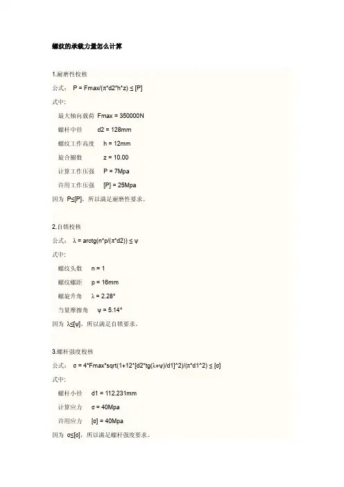
螺纹的承载力量怎么计算1.耐磨性校核公式:P=Fmax/(π*d2*h*z)≤[P]式中:最大轴向载荷Fmax=350000N螺杆中径d2=128mm螺纹工作高度h=12mm旋合圈数z=10.00计算工作压强P=7Mpa许用工作压强[P]=25Mpa因为P≤[P],所以满足耐磨性要求。
2.自锁校核公式:λ=arctg(n*p/(π*d2))≤ψ式中:螺纹头数n=1螺纹螺距p=16mm螺旋升角λ=2.28°当量摩擦角ψ=5.14°因为λ≤[ψ],所以满足自锁要求。
3.螺杆强度校核公式:σ=4*Fmax*sqrt(1+12*[d2*tg(λ+ψ)/d1]^2)/(π*d1^2)≤[σ]式中:螺杆小径d1=112.231mm计算应力σ=40Mpa许用应力[σ]=40Mpa因为σ≤[σ],所以满足螺杆强度要求。
4.螺纹牙强度校核公式:τ=Fmax/(π*dt*b*z)≤[τ]σ=3*Fmax*h/(π*dt*b^2*z)≤[σ]式中:螺纹牙底宽度b=11.84mm螺母和螺杆材料不同,取dt=d+2*Y=143.769mm 螺杆大径d=140mm螺纹顶隙Y=1.88432mm计算剪切强度τ=7Mpa许用剪切强度[τ]=35Mpa计算弯曲强度σ=20Mpa许用弯曲强度[σ]=45Mpa因为τ≤[τ]且σ≤[σ],所以满足螺纹牙强度要求。
5.螺杆稳定性校核公式:Scr=20600*π^3*d1^4/(64*Fmax*(μ*l)^2)〉Sc 式中:螺杆长度系数μ=0.7螺杆工作长度l=300mm稳定性计算安全系数Scr=102.59稳定性安全系数Sc=3.8因为Scr〉Sc,所以满足稳定性要求。
滚动轴承承载能力计算分析目录1 分析基础 (1)1.1理论基础:Hertz弹性体接触理论 (1)1.2实验基础:许用接触应力 (2)2 承载分析 (3)2.1曲率计算 (3)2.2轴向承载 (4)2.3径向承载 (6)2.4倾覆承载能力 (10)2.5当量轴向力 (12)3静容量系数f0系数确定 (13)3.1许用接触应力 (13)3.2静容量系数 (14)4算例 (16)4.1基本参数 (16)4.2曲率计算 (16)4.3计算接触应力常数Cp值 (16)4.4计算许用接触应力 (16)4.5计算静容量系数f0值 (17)4.6静容量计算 (17)5简化(统一)计算法 (18)5.1简化公式 (18)5.2不同曲率比时的静容量系数值 (18)6 附录 (19)附表1:曲率函数F(ρ)有关的椭圆积分 (19)附表2:不同球数时的Jr值 (21)1 分析基础1.1 理论基础:Hertz 弹性体接触理论由Hertz 推导出的点接触弹性变形和接触应力计算基本公式:32113∑⎪⎭⎫ ⎝⎛-⋅=ρμQm E a (1-1) 32113∑⎪⎭⎫ ⎝⎛-⋅=ρνQm E b (1-2) abQ23max πσ=(1-3) Q Ea m e K )11()(25.12-=πδ (1-4) 式中 a ——接触椭圆长半轴 (mm ) b ——接触椭圆短半轴 (mm ) σmax ——最大接触应力(N/mm2)δ——弹性趋近量 (mm )μ、ν——与曲率函数F (ρ)有关的椭圆积分,取值见附表1 E ——材料弹性模量(N/mm 2)m1——材料泊松比Q ——使两接触体压紧的法向载荷 (N ) ∑ρ——接触处主曲率之和 K(e)——第一类椭圆完全积分。
1.2 实验基础:许用接触应力Hertz 弹性接触理论不可能包括塑性变形,但在塑性变形区仍然引用Hertz 接触理论,并假定塑性变形b δ与滚动体直径D w 有关,即用b δ/D w 来表示塑性变形。
轴承轴向承力极限摘要:1.轴承轴向承载能力的概念2.深沟球轴承的轴向承载能力3.圆柱滚子轴承的轴向承载能力4.圆锥滚子轴承的轴向承载能力5.轴承轴向承载能力的计算方法正文:一、轴承轴向承载能力的概念轴承轴向承载能力是指轴承在承受轴向负荷时,能够承受的最大负荷。
在工程应用中,了解轴承的轴向承载能力对于保证设备的正常运行和延长轴承的使用寿命具有重要意义。
二、深沟球轴承的轴向承载能力深沟球轴承在承受轴向负荷时,其极限轴向承载能力一般不应超过0.5c0 的值。
其中,c0 表示轴承的基本径向间隙。
对于小型轴承(内径约在12 毫米以内)和轻型系列轴承(直径系列8、9、0 和1),其轴向负荷不应超过0.25c0 的值。
若轴向负荷过大,会大大缩短轴承的使用寿命。
三、圆柱滚子轴承的轴向承载能力圆柱滚子轴承在实际应用中是不应该承受轴向力的,否则会在滚道角处产生非正常应力而造成轴承损坏。
因此,在实际应用中,圆柱滚子轴承应与能承受轴向载荷作用的轴承一起使用。
四、圆锥滚子轴承的轴向承载能力圆锥滚子轴承的滚动体是锥形滚轴,其内部结构和重量全系列。
此类轴承有多种内部结构及重量全系列,所装配G2 级滚针,分组批直径变动量在2um 以内,除满装滚缝轴承外,均使用高性保持架。
圆锥滚子轴承的轴向承载能力较强,能够承受较大的轴向负荷。
五、轴承轴向承载能力的计算方法计算轴承轴向承载能力时,需要考虑轴承的材料、尺寸、负荷类型等因素。
具体的计算公式较为复杂,需要根据轴承的具体参数进行计算。
在实际应用中,通常采用实验公式进行估算,例如深沟球轴承的轴向承载能力计算公式为:fap(k1c010000)/n(dd)-k2fr。
滑动轴承论文:滑动轴承承载能力的理论研究和实验分析【中文摘要】在生产实践中,轴承的承载能力是滑动轴承设计的重点问题,对滑动轴承承载能力的研究对于轴承技术的发展具有重要意义。
通常影响滑动轴承承载能力的因素有很多,如宽径比、偏心率、相对间隙等,而滑动轴承在不同工作载荷和转速的情况下,油膜承载力也不尽相同。
本文应用数值计算方法以及编程语言,从理论计算和实验测试两个方面对滑动轴承的承载能力展开研究。
本文对雷诺方程进行无量纲简化,采用有限差分法和超松弛迭代法以及数学软件MATLAB对简化后的雷诺方程编程求解,获得滑动轴承油膜压力分布数值以及三维图形,并研究了轴承宽径比、偏心率对轴承油膜压力分布的影响规律。
本文利用ZHS20滑动轴承实验台测得在不同工作载荷及转速下滑动轴承的油膜压力分布,以及流体动力润滑特性相关曲线,展开对滑动轴承摩擦因数、摩擦状态转化以及过渡转速的研究,并对理论计算以及实验台测试所得的轴承承载力进行比较,引入端泄系数,对轴承运行的端泄量展开研究。
本文通过对实验台测试功能的拓展,测得不同相对间隙下轴承的油膜压力分布,分析相对间隙对轴承承载力的影响,并通过计算得到使轴承获得最大承载力的相对间隙最佳值,对滑动轴承的设计和研究具有实际指导意义。
本文在最后对轴承承载力的理论计算和实验值计算进行可视化操作界面设计,使轴承承载力的计算及其结果显示更为形象、简捷。
【英文摘要】The capacity of bearing is the key point ofjournal bearing’s design in production practice, which is extremely important to the bearing technology development. Usually, there are many factors influence the capacity of journal bearing, such as the wide of axle bush compared to diameter of axle, eccentricity, relative gap, and the lubricant film supporting capacity is also different in the different work load and in the rotational speed situation.This article adopts the numerical calculus method and the programming language, to research the capacity of journal bearing through the way of the theoretical calculation and the experiment value. This article simplifies the Reynolds equation into dimensionless form, and uses the finite difference method and the ultra flaccid repetitive process as well as mathematics software MATLAB to program and solve the dimensionless form of the Reynolds equation, and obtains the pressure distribution value and the three dimensional graph of journal bearing lubricant film, and also studies the bearing film pressure distribution influence rule of the wide of axle bush compared to diameter of axle and eccentricity. Under the different work load and the rotational speed, this article uses the journal bearing laboratory bench ZHS20 to obtain the journal bearing’s lubricant film pressure distribution and the hydrodynamiclubrication characteristic correlation curve, and research the journal bearing rubbing factor, the friction condition transformation and the excessive rotational speed, compares the bearing supporting capacity of theoretical calculation and the experiment value, gives the coefficient of the leading-in terminal releases, studies the quantity of releases when the bearing is working. Through to develop the test function of the laboratory bench, this article obtains the bearing’s lubricant film pressure distribution under different relative gap, and analyses the influence of the relative gap to the bearing supporting capacity, and obtains the relative gap best value which can cause the bearing to get the greatest supporting capacity. At last, this article carries on the visualization operation contact surface design to the bearing supporting capacity which contains the theoretical calculation value and the actual computation value, and the contact surface makes the computation and the demonstration of result much vividly, simply and directly.【关键词】滑动轴承理论计算实验研究 MATLAB 相对间隙可视化【英文关键词】Journal bearing Fundamental calculation Experiment research MATLABRelative gap Visualization【目录】滑动轴承承载能力的理论研究和实验分析摘要6-7Abstract7第1章绪论10-151.1 课题来源101.2 国内外研究历史及现状10-131.2.1 滑动轴承发展历史及研究概况10-111.2.2 滑动轴承实验台发展现状11-131.3 课题研究方案及技术路线131.4 研究意义13-141.5 本章小结14-15第2章滑动轴承承载能力理论研究15-222.1 雷诺方程的求解15-202.1.1 雷诺方程的无量纲化15-162.1.2 确定边界条件16-172.1.3 求解雷诺方程17-202.1.3.1 计算网格划分172.1.3.2 方程的离散化17-192.1.3.3 逐点松弛迭代法19-202.1.3.4 收敛准则202.2 雷诺方程的程序编译及计算20-212.3 本章小结21-22第3章滑动轴承承载能力实验与数据处理22-333.1 滑动轴承实验台简介22-233.2 实验数据采集23-283.2.1 径向滑动轴承油膜压力分布曲线实验24-263.2.2 流体动力润滑特性曲线实验26-283.3 实验数据处理28-323.3.1 实验数据的曲线拟合28-303.3.2 数据拟合结果30-323.4 本章小结32-33第4章滑动轴承承载能力分析与研究33-494.1 滑动轴承理论计算参数影响的研究33-374.1.1 滑动轴承宽径比的影响33-344.1.2 滑动轴承偏心率的影响34-374.2 滑动轴承摩擦因数的实验研究37-434.2.1 滑动轴承摩擦状态的转化374.2.2 实验数据的整理与分析37-414.2.2.1 f-λ曲线测定37-394.2.2.2 p-f-n曲线测定39-414.2.3 摩擦因数的分析与研究41-434.2.3.1 f-λ曲线的分析414.2.3.2 p-f-n曲线的分析41-424.2.3.3 摩擦因数的理论计算值与实验值比较分析42-434.3 承载能力理论值与实验值分析43-454.3.1 承载力实验值计算43-444.3.2 承载力理论值计算44-454.3.3 承载力实验值与理论值的对比研究454.4 相对间隙改变时承载能力的研究45-484.5本章小结48-49第5章滑动轴承承载能力曲线的可视化49-575.1 GUI模块简介49-505.2 滑动轴承承载力实验值的可视化50-555.2.1 创建GUI图形界面50-535.2.2 编写回调函数53-555.3 滑动轴承承载力理论计算的可视化55-565.4 本章小结56-57结论57-59致谢59-60参考文献60-62攻读硕士学位期间发表的论文62。
6207 轴承载荷判定系数解释说明以及概述1. 引言1.1 概述在工程设计和制造过程中,轴承是一种重要的机械元件,常被用于传递动力和支撑旋转部件。
而轴承的载荷判定系数是评估轴承性能的核心参数之一,对于确保轴承正常运行具有重要意义。
本文将着重探讨6207轴承载荷判定系数的解释说明以及概述。
1.2 文章结构本文将从以下几个方面对6207轴承载荷判定系数进行解释说明以及概述。
首先,我们会介绍6207轴承的基本概念,包括其定义、功能和应用范围。
接着,我们将详细分析轴承载荷及其影响因素,以帮助读者全面了解载荷对轴承性能的影响。
然后,我们会深入探讨6207轴承载荷判定系数的定义与意义,揭示其在评估轴承可靠性和寿命方面所起到的关键作用。
最后,我们将介绍计算6207轴承载荷判定系数的方法,并给出实例分析与应用注意事项。
1.3 目的本文的目的是帮助读者全面理解6207轴承载荷判定系数及其计算方法,提供应用案例和实践经验分享,为工程师在轴承设计与选择过程中提供参考和指导。
通过阅读本文,读者将能够更好地应用轴承载荷判定系数,提高轴承的可靠性和寿命,从而确保设备正常运行并减少故障率。
这样完成了第一个部分。
2. 6207轴承载荷判定系数解释说明2.1 6207轴承基本概念6207轴承是一种常见的球形滚子轴承,它由内圈、外圈、钢球和保持架组成。
内圈和外圈的接触表面是球形的,这使得轴承能够在各个方向上承受相对较大的载荷。
它具有良好的旋转性能和耐久性,在机械设备中广泛应用。
2.2 轴承载荷及其影响因素轴承在使用过程中需要承受来自外界的载荷作用,主要包括径向载荷和轴向载荷两种类型。
径向载荷是垂直于轴线方向作用于轴承的力,而轴向载荷则是沿着轴线方向作用于轴承的力。
除了这两种主要载荷之外,还有其他因素也会对轴承产生影响,比如转速、温度、润滑方式等。
2.3 轴承载荷判定系数的定义与意义为了确定一个特定型号和尺寸的6207轴承是否适合在某种工况下使用,我们需要计算轴承的载荷判定系数。
三排滚子转盘轴承承载能力分析和寿命计算摘要多排滚柱式回转支撑,能够承受较大的倾覆力矩,是回转支承中承载能力最大的一种。
多排滚柱式回转支承特别适用于承受大载荷、大冲击工况条件下运行的重型机械,而三排滚柱式回转支承是其中最具典型的结构形式,因此对三排滚子转盘轴承的研究具有一定的现实意义和社会效益。
以Hertz接触理论为基础,结合三排滚子转盘轴承的特殊结构,推导出计算三排滚子转盘轴承接触强度校核的有关理论公式,并绘制了静、动承载能力曲线。
然后,用Lundberg-Palmgren寿命理论,推导计算三排滚子转盘轴承的疲劳寿命。
通过以上的分析计算可为轴承的选型和设计提供理论基础。
通过以上分析推导的公式,建立数值求解模型,用Matlab编程语言进行计算求解,解出三排滚子转盘轴承的最大承受载荷和寿命,进而绘制承载能力曲线。
之后,再用ANSYS有限元,建立简单的模型进行形变和应力的分析。
关键词:三排滚子转盘轴承,承载能力,疲劳寿命,经典数值分析,ANSYS有限元分析。
CARRYING CAPACITY ANALYSIS AND LIFETIME CALCULATIONS OF THREE-ROWROLLER SLEWING BEARINGSABSTRACTIn slewing bearings, the multi-row roller slewing bearings has the most load carrying capacity, which can withstand large overturning moment. The multi-row roller slewing bearings is especially suitable for heavy machinery which withstand large loads or impact of working conditions under running. However, three-row roller slewing bearings is one of the most typical form in the structure of multi-row roller slewing bearings. So, it has a certain practical significanc e and social benefits for studing three-row roller slewing bearings.It can deduce to the theoretical formula that used to calculating contact strength check of the three-row roller slewing bearings and can draw static and dynamic carrying capacity curves,based on the Hertz contact theory and combined with the special structure of the three-row roller slewing bearings. Then, using the lifetime expectancy theory of Lundberg-Palmgren to derived and calculate the fatigue lifetime of the three-row roller slewing bearings. It can provide a theoretical basis for bearing type selection and design by the above anal ysis and calculations.Through the formula which anal ysis and derive above,we can build the numerical solution model. Computing f or Matlab programming language, solve three-row roller slewing bearings maximum load carrying and lifetime, and then draw the carrying capacity curve. After then, build a simple model by the ANSYS finite element to deformation and stress analysis.KEY WORDS:three-row roller slewing bearings, carrying capacity, fatigue lifetime, Classical numerical analysis, ANSYS finite element analysis.目录前言 (1)第1章绪论 (2)§1.1研究对象 (2)§1.1.1研究对象及特点 (2)§1.1.2国内外对比 (3)§1.2研究的意义 (3)第2章静承载能力分析 (4)§2.1负荷和变形 (4)§2.1.1负荷与弹性变形 (4)§2.2 接触应力和变形计算 (5)§2.2.1赫兹弹性理论的基本假设 (5)§2.2.2计算公式 (5)§2.3平衡方程 (6)§2.3.1静态平衡方程的建立 (6)§2.3.2力平衡方程 (6)§2.3.3力矩平衡方程 (8)§2.4承载曲线的绘制 (8)§2.4.1分析计算过程 (8)§2.4.2静承载曲线的绘制 (11)第3章额定寿命和动态承载能力的计算 (13)§3.1理论公式的推导 (13)§3.1.1额定滚动体负荷计算 (13)§3.1.2当量滚动体负荷计算 (13)§3.1.3单个套圈额定寿命计算 (13)§3.2多排滚子的合成寿命计算 (15)§3.3动承载能力曲线的绘制 (15)§3.4动静承载能力合成曲线 (17)第4章承载能力的有限元分析 (18)§4.1有限元模型的确定 (18)§4.2 承载能力的有限元求解 (18)§4.2.1 求解步骤 (18)§4.2.2 网格划分过程 (19)§4.2.3 求解和分析 (20)§4.3 求解之后的结论 (21)结论 (22)参考文献 (23)致谢 (25)附录 (26)§1.1求转盘轴承滚子参数的主函数 (26)§1.2求转盘轴承参数的子函数 (30)§1.3求转盘轴承寿命的主函数 (33)§1.4求转盘轴承寿命的子函数 (35)前言由于现在对转盘轴承的研究只限制在四点接触转盘轴承上,对三排滚子转盘轴承的研究很少,多排滚柱式回转支承与球式回转支承相比特别适用于承受大载荷、大冲击工况条件下运行的重型机械,而三排滚柱式回转支承是其中最具典型的结构形式,因此对三排滚子转盘轴承的研究具有一定的现实意义和社会效益。