光电稳定滑模变结构控制系统的设计与仿真
- 格式:pdf
- 大小:273.98 KB
- 文档页数:5
摘要舵伺服系统在航空航天领域,有着广泛应用和重要的研究价值。
应用无刷直流电机作为舵系统执行器,可以增大系统输出转矩,实现系统小型化。
本文基于无刷直流电机执行器,利用 DSP 与 FPGA 结合的核心处理单元,应用滑模变结构控制策略,实现舵机系统伺服,提高舵系统抗扰性和信号响应的快速性;并在系统中加入滑模观测器,实现对于系统内部状态量的观测,为实现无位置传感器控制提供条件本文应用无刷直流电机作为舵系统执行器,通过分析和设计滑模变结构控制算法,实现舵系统位置伺服控制,利用滑模变结构控制策略的特性,提高系统对于扰动和内部参数摄动的鲁棒性,与基于传统控制策略的伺服机构相比,系统的抗扰性得到了提高。
并在系统中引入滑模观测器,利用电流、电压传感器采样相电流和相电压作为该观测器的给定量,观测出电机的速度,转子运动换相位置信号和三相反电动势波形,从而实现电机的无位置传感器控制。
本文通过分析舵伺服机构的主要结构和工作原理,根据实际系统技术要求,设计出基于电动伺服系统的数字控制器。
利用 DSP 强大的数据处理能力和 FPGA 并行运算能力,实现设计的控制算法,提高舵系统的性能。
通过 MATLAB 中 Simulink 环境下构建理想系统模型,应用滑模控制算法,进行模型仿真。
通过系统仿真分析,设计出满足离散系统的滑模控制器参数。
通过 DSP 与 FPGA 结合的核心处理单元实现滑模变结构控制算法,应用于舵伺服系统中[1]。
最后,通过完成整体硬件与软件平台设计,实现对舵伺服系统的控制。
通过仿真和实验结果分析,验证了滑模控制具有强鲁棒性和抗扰性,满足舵系统对于快速性和抗扰性的技术要求,提高了系统整体控制性能。
关键字:滑模控制;滑模观测器;无刷直流电机;舵伺服系统;DSP+FPGABrushless dc motor of the sliding mode controller designand simulationAbstractRudder servo system is used in the aerospace field, it has important research value. Using BLDCM as the rubber system actuator, it will improve the system’s output torque, and achieve system’s miniaturization. Based on BLDCM actuator, combined DSP and FPGA as the core processing unit, using the strategy of sliding mode variable structure control achieve the rubber servo system which improve the robustness for disturbances and the speed for signal response. Adding sliding mode observer in the system realize the observation of internal system state which provide reliable parameters for the realization of position sensorless controlThrough a brief analysis of rudder servo on both the main structure and working principle, based on the actual system technical requirements, this paper designs a digital controller which is based on electric servo system. Using DSP and FPGA as the core control unit, and the strong ability of DSP data processing and the ability of FPGA parallel computing , achieve the design of control algorithms, and improve performance of rubber systemUsing BLDCM as the servo system actuator, through analysis and designing the algorithm of sliding mode control, this paper achieves the position servo control in rubber system. Using the characteristic of sliding mode variable structure improve the robustness for disturbance and inner parameters transformation. Compared with the control strategy based on traditional servo system, it improves the immunity of servo system. And addingsliding mode observer in the system, use circuit sensors and voltage sensors sample phase circuit and phase voltage as the giving quantities to observer. This paper rely on observer getting the motor’s speed, moving rotor’s changing phase position signal and three-phases waveforms of back-EMF, so that achieve the sensorless motor control Using Simulink in MATLAB build the ideal mode of the real system and the algorithms of sliding mode, and carry out mode simulation.Through the system simulation, design a sliding mode controller which meet the parameters of discrete systems, and through the combination of DSP and FPGA core processing unit realize control algorithm, which is applied to the rudder servo system. At last, finishing the design of whole hardware and software, realize the control of rubber servo system. Through the simulation and experiment, testified sliding mode control has strongly robustness and immunity for disturbance. This meets the rubber system’s technology requirements including rapid and immunity for disturbance, and improves overall system’s control performanc eKeywords:Sliding mode control,Sliding mode observer,BLDCM,Rubber servo system,DSP+FPGA目录摘要 (I)Abstract.................................................................................................................................................... I I 第1章绪论. (1)1.1 课题背景及研究的目的和意义 (1)1.2 国内外伺服研究现状 (2)1.3 无刷直流电机控制方法 (2)1.3.1 传统的控制方法 (3)1.3.2 模糊控制方法 (3)1.3.3 鲁棒控制方法 (3)1.3.4 神经网络控制方法 (4)1.3.5 自适应控制方法 (4)1.3.6 滑模变结构控制方法 (4)1.4 伺服系统应用的主要问题 (5)1.5 课题研究的主要内容 (6)第2章伺服系统的构成与数学模型 (8)2.1 伺服系统的总体结构 (8)2.1.1 无刷直流电机的选择 (9)2.1.2 伺服系统驱动方式 (9)2.2 无刷直流电机的工作原理 (9)2.3 无刷直流电机数学模型 (15)2.3.1 无刷直流电机的方程 (15)2.3.2 无刷直流电机的状态方程 (16)2.3.3 无刷直流电机的电磁转矩方程 (16)2.3.4 无刷直流电机的运动方程 (17)2.3.5 无刷直流电机的机械特性 (17)第3章滑模变结构理论 (18)3.1滑模变结构控制的基本原理 (18)3.2滑模运动及其存在和到达条件 (19)3.3滑模变结构控制 (19)3.3.1滑模变结构控制器设计 (19)3.3.2切换函数的设计 (19)3.3.3控制律的设计 (20)3.4抖振改善 (20)第4章基于滑模变结构的控制系统设计 (21)4.1 滑模控制器 (21)4.2 滑模观测器 (26)4.3 系统仿真与结果分析 (28)4.4 本章小结 (34)第五章结论 (35)参考文献 (38)谢辞 (40)第1章绪论1.1课题背景及研究的目的和意义随着科技的发展,伺服系统应用领域更加广泛,主要应用于智能机床、机器人、导弹制导以及船舶、车辆的自驾驶,可以说是实现未来工业全自动智能化必不可少的环节。
控制理论-滑模变结构控制1、滑模变结构控制简介变结构控制( Variable Structure Control,VSC)本质上是⼀类特殊的⾮线性控制,其⾮线性表现为控制的不连续性;这种控制策略与其他控制的不同之处在于系统的“结构”并不固定,⽽是可以在动态过程中,根据系统当前的状态(如偏差及其各阶导数等),有⽬的地不断变化,迫使系统按照预定“滑动模态”的状态轨迹运动,所以⼜常称变结构控制为滑动模态控制( Sliding Mode Control,SMC),即滑模变结构控制。
由于滑动模态可以进⾏设计且与对象参数及扰动⽆关,这就使得变结构控制具有快速响应、对参数变化及扰动不灵敏、⽆须系统在线辦识,物理实现简单等优点。
该⽅法的缺点在于当状态轨迹到达滑模⾯后,难于严格地沿着滑⾯向着平衡点滑动,⽽是在滑模⾯两侧来回穿越,从⽽产⽣颤动。
总之,抖振产⽣的原因在于:当系统的轨迹到达切换⾯时,其速度是有限⼤,惯性使运动点穿越切换⾯,从⽽最终形成抖振,叠加在理想的滑动模态上。
对于实际的计算机采样系统⽽⾔,计算机的⾼速逻辑转换及⾼精度的数值运算使得切换开关本⾝的时间及空间滞后影响⼏乎不存在;因此,开关的切换动作所造成控制的不连续性是抖振发⽣的本质原因。
2、未建模动态按照我的理解,在控制系统中,我们往往⾯对的是⾼阶的系统,⽽我们的分析和设计常常⾯对的是低阶的系统,即所谓的⽤低阶系统来近似模拟⾼阶系统的特性。
通常我们能通过低阶系统获得与⾼阶系统相近似的动态性能。
注意这⾥说的是近似的,也就是说⾼阶系统还有⼀部分动态性能我们⽤低阶系统来分析时会忽略掉。
⽽忽略的这部分就是未建模动态。
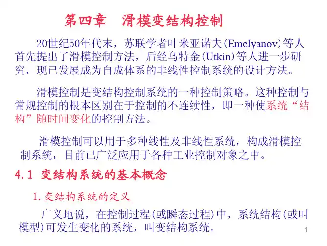
3、滑模变结构控制基本原理滑模变结构控制是变结构控制系统的⼀种控制策略。
这种控制策略与常规控制的根本区别在于控制的不连续性,即⼀种使系统“结构”随时间变化的开关特性。
该控制特性可以迫使系统在⼀定特性下沿规定的状态轨迹作⼩幅度、⾼频率的上下运动,即所谓的滑动模态或“滑模”运动。
滑模控制和滑膜变结构控制1. 引言滑模控制和滑膜变结构控制是现代控制理论中重要的控制策略,广泛应用于各个领域的控制系统中。
滑模控制通过引入一个滑模面来实现系统的稳定性和鲁棒性;滑膜变结构控制通过在线调整系统的结构以适应不确定性和外部扰动。
2. 滑模控制滑模控制最早由俄罗斯科学家阿莫斯特芬于1968年提出,并在1974年得到了进一步的发展。
滑模控制通过引入一个滑模面,将系统状态从非线性区域滑到线性区域,从而实现系统的稳定性和鲁棒性。
2.1 滑模面滑模面是滑模控制的核心概念之一,它通常由一个超平面表示,可以用数学方程描述为:s=Sx其中,s为滑模面,S为一个可逆矩阵,x为系统的状态变量。
2.2 滑模控制律滑模控制律用于调节系统状态,以使系统状态滑到滑模面上。
滑模控制律的一般形式可以表示为:u=−S−1B Tλ(s)其中,u为控制输入,B为输入矩阵,λ(s)为滑模曲线。
2.3 滑模控制的优点滑模控制具有以下几个优点:•鲁棒性强:滑模控制能够在面对参数扰动和外部干扰时保持系统的稳定性。
•快速响应:由于滑模面能够将系统状态快速滑到线性区域,使得系统具有快速响应的特性。
•无需精确模型:滑模控制不需要系统的精确模型,因此对于复杂系统的控制较为便捷。
3. 滑膜变结构控制滑膜变结构控制(SMC)由美国科学家丹尼尔·尤斯托曼在20世纪90年代末提出,是一种基于滑模控制的新型控制策略。
滑膜变结构控制通过在线调整系统的结构以适应不确定性和外部扰动,从而提高系统的鲁棒性和性能。
3.1 滑膜设计滑膜变结构控制的关键是设计一个合适的滑膜来响应系统的不确定性和扰动。
滑膜通常由一个或多个滑模面组成,通过在线调整滑膜的参数,可以适应不同的工作条件和控制要求。
3.2 滑膜变结构控制律滑膜变结构控制律的一般形式可以表示为:u=−K(θ)s−δ(θ)sign(s)其中,u为控制输入,K(θ)和δ(θ)分别为滑膜参数和输出增益,θ为参数向量,s为滑模曲线。


摘要舵伺服系统在航空航天领域,有着广泛应用和重要的研究价值。
应用无刷直流电机作为舵系统执行器,可以增大系统输出转矩,实现系统小型化。
本文基于无刷直流电机执行器,利用 DSP 与 FPGA 结合的核心处理单元,应用滑模变结构控制策略,实现舵机系统伺服,提高舵系统抗扰性和信号响应的快速性;并在系统中加入滑模观测器,实现对于系统内部状态量的观测,为实现无位置传感器控制提供条件本文应用无刷直流电机作为舵系统执行器,通过分析和设计滑模变结构控制算法,实现舵系统位置伺服控制,利用滑模变结构控制策略的特性,提高系统对于扰动和内部参数摄动的鲁棒性,与基于传统控制策略的伺服机构相比,系统的抗扰性得到了提高。
并在系统中引入滑模观测器,利用电流、电压传感器采样相电流和相电压作为该观测器的给定量,观测出电机的速度,转子运动换相位置信号和三相反电动势波形,从而实现电机的无位置传感器控制。
本文通过分析舵伺服机构的主要结构和工作原理,根据实际系统技术要求,设计出基于电动伺服系统的数字控制器。
利用 DSP 强大的数据处理能力和 FPGA 并行运算能力,实现设计的控制算法,提高舵系统的性能。
通过 MATLAB 中 Simulink 环境下构建理想系统模型,应用滑模控制算法,进行模型仿真。
通过系统仿真分析,设计出满足离散系统的滑模控制器参数。
通过 DSP 与 FPGA 结合的核心处理单元实现滑模变结构控制算法,应用于舵伺服系统中[1]。
最后,通过完成整体硬件与软件平台设计,实现对舵伺服系统的控制。
通过仿真和实验结果分析,验证了滑模控制具有强鲁棒性和抗扰性,满足舵系统对于快速性和抗扰性的技术要求,提高了系统整体控制性能。
关键字:滑模控制;滑模观测器;无刷直流电机;舵伺服系统;DSP+FPGABrushless dc motor of the sliding mode controller designand simulationAbstractRudder servo system is used in the aerospace field, it has important research value. Using BLDCM as the rubber system actuator, it will improve the system’s output torque, and achieve system’s miniaturization. Based on BLDCM actuator, combined DSP and FPGA as the core processing unit, using the strategy of sliding mode variable structure control achieve the rubber servo system which improve the robustness for disturbances and the speed for signal response. Adding sliding mode observer in the system realize the observation of internal system state which provide reliable parameters for the realization of position sensorless controlThrough a brief analysis of rudder servo on both the main structure and working principle, based on the actual system technical requirements, this paper designs a digital controller which is based on electric servo system. Using DSP and FPGA as the core control unit, and the strong ability of DSP data processing and the ability of FPGA parallel computing , achieve the design of control algorithms, and improve performance of rubber systemUsing BLDCM as the servo system actuator, through analysis and designing the algorithm of sliding mode control, this paper achieves the position servo control in rubber system. Using the characteristic of sliding mode variable structure improve the robustness for disturbance and inner parameters transformation. Compared with the control strategy based on traditional servo system, it improves the immunity of servo system. And addingsliding mode observer in the system, use circuit sensors and voltage sensors sample phase circuit and phase voltage as the giving quantities to observer. This paper rely on observer getting the motor’s speed, moving rotor’s changing phase position signal and three-phases waveforms of back-EMF, so that achieve the sensorless motor control Using Simulink in MATLAB build the ideal mode of the real system and the algorithms of sliding mode, and carry out mode simulation.Through the system simulation, design a sliding mode controller which meet the parameters of discrete systems, and through the combination of DSP and FPGA core processing unit realize control algorithm, which is applied to the rudder servo system. At last, finishing the design of whole hardware and software, realize the control of rubber servo system. Through the simulation and experiment, testified sliding mode control has strongly robustness and immunity for disturbance. This meets the rubber system’s technology requirements including rapid and immunity for disturbance, and improves overall system’s control performanc eKeywords:Sliding mode control,Sliding mode observer,BLDCM,Rubber servo system,DSP+FPGA目录摘要 (I)Abstract.................................................................................................................................................... I I 第1章绪论. (1)1.1 课题背景及研究的目的和意义 (1)1.2 国内外伺服研究现状 (2)1.3 无刷直流电机控制方法 (2)1.3.1 传统的控制方法 (3)1.3.2 模糊控制方法 (3)1.3.3 鲁棒控制方法 (3)1.3.4 神经网络控制方法 (4)1.3.5 自适应控制方法 (4)1.3.6 滑模变结构控制方法 (4)1.4 伺服系统应用的主要问题 (5)1.5 课题研究的主要内容 (6)第2章伺服系统的构成与数学模型 (8)2.1 伺服系统的总体结构 (8)2.1.1 无刷直流电机的选择 (9)2.1.2 伺服系统驱动方式 (9)2.2 无刷直流电机的工作原理 (9)2.3 无刷直流电机数学模型 (15)2.3.1 无刷直流电机的方程 (15)2.3.2 无刷直流电机的状态方程 (16)2.3.3 无刷直流电机的电磁转矩方程 (16)2.3.4 无刷直流电机的运动方程 (17)2.3.5 无刷直流电机的机械特性 (17)第3章滑模变结构理论 (18)3.1滑模变结构控制的基本原理 (18)3.2滑模运动及其存在和到达条件 (19)3.3滑模变结构控制 (19)3.3.1滑模变结构控制器设计 (19)3.3.2切换函数的设计 (19)3.3.3控制律的设计 (20)3.4抖振改善 (20)第4章基于滑模变结构的控制系统设计 (21)4.1 滑模控制器 (21)4.2 滑模观测器 (26)4.3 系统仿真与结果分析 (28)4.4 本章小结 (34)第五章结论 (35)参考文献 (38)谢辞 (40)第1章绪论1.1课题背景及研究的目的和意义随着科技的发展,伺服系统应用领域更加广泛,主要应用于智能机床、机器人、导弹制导以及船舶、车辆的自驾驶,可以说是实现未来工业全自动智能化必不可少的环节。
·30·兵工自动化Ordnance Industry Automation2021-0540(5)doi: 10.7690/bgzdh.2021.05.008机载光电稳定平台的强鲁棒性滑模变结构控制马经帅,于洵,韩峰(西安工业大学兵器科学与技术学院,西安 710000)摘要:为使机载光电稳定平台系统在复杂环境下仍具有强鲁棒性,建立光电稳定平台数学模型。
以两轴四框架光电吊舱为研究对象,通过分析噪声干扰及本身结构参数的变化对光电稳定平台的影响,提出基于干扰观测器(disturbance observer,DOB)的滑模控制器设计方案。
理论推导和仿真结果表明:滑模变结构控制(sliding mode variable structure control,SMVSC)对干扰力矩和摄动完全适应,对系统结构参数变化和外界扰动具有良好的鲁棒性;比无干扰观测器的控制系统,拥有更高的稳定精度和更快的动态响应,能增强光电稳定平台的抗扰动能力。
关键词:光电稳定平台;滑模变结构控制;干扰观测器;强鲁棒性中图分类号:TP273 文献标志码:AStrong Robust Sliding Mode Variable Structure Control inAirborne Photoelectric Stabilized PlatformMa Jingshuai, Yu Xun, Han Feng(College of Ordnance Science & Technology, Xi’an Technological University, Xi’an 710000, China) Abstract: In order to make the airborne optoelectronic stabilized platform system still have strong robustness in complex environments, a mathematical model of the optoelectronic stabilized platform is established. Taking the two-axis four-frame photoelectric pod as the research object, by analyzing the influence of noise interference and changes in its structural parameters on the photoelectric stabilized platform, a design scheme of sliding mode controller based on disturbance observer (DOB) is proposed. Theoretical derivation and simulation results show that: sliding mode variable structure control (SMVSC) is fully adaptable to disturbance torque and perturbation, and has good robustness to system structural parameter changes and external disturbances; it has higher performance than control systems without disturbance observers. Stable accuracy and faster dynamic response enhance the anti-disturbance capability of the photoelectric stabilized platform.Keywords: photoelectric stabilization platform; SMVSC; DOB; strong robustness0引言机载光电稳定平台一般由光电载荷、陀螺、框架结构、驱动及控制系统等组成,是一种光、机、电高度集成的精密设备,用于目标的搜索捕获和跟踪等。