ER-GN30使用说明书
- 格式:pdf
- 大小:4.29 MB
- 文档页数:28


HUMAN MACHINEINTERFACESENERGYMANAGEMENTSOLUTIONSFA COMPONENTSMACHINE VISIONSYSTEMSUV CURINGSYSTEMSCX-400CY-100EX-10EX-20EX-30EX-40CX-440EQ-500MQ-WRX-LS200RXRT-610Hardly affected by object color or backgroundAs the EQ-30 series is incorporated with a 2-segmentphotodiode as the receiving element with a uniquecircuitry, it detects an object at the same distanceregardless of its color or the background beyond theadjusted sensing range.However, when the background is specular, it may benecessary to change the angle of the sensor.Long sensing range 2 m 6.562 ftThe EQ-30 series can detect an object 2 m 6.562 ftaway.It is suitable for various applications, such as, sensingobjects or positioning objects traveling on a wideassembly line, etc.2 m6.562 ft1 m3.281 ft0.2 m0.656 ftSensingrangeL(mftBlackrubberWhitenon-glossypaperGraynon-glossypaper(Lightness:5CardboardPlywoodThese bars indicate the sensing range with therespective objects when the distance adjuster isset at the sensing range of 2 m 6.562 ft, 1 m3.281 ft and 0.2 m 0.656 ft long, each, with whitenon-glossy paper.EQ-34: Correlation between material (200 × 200 mm 7.874× 7.874 in) and sensing range (typical)Adjustable Range Reflective Photoelectric SensorEQ-30 SERIES322FIBER SENSORS LASER SENSORS PHOTOELECTRIC SENSORS AREASENSORS SAFETY LIGHT CURTAINS /SAFETY COMPONENTS PRESSURE / FLOWSENSORS INDUCTIVE PROXIMITY SENSORSPARTICULAR USE SENSORS SENSOR OPTIONS SIMPLEWIRE-SAVING UNITS WIRE-SAVING SYSTEMS MEASUREMENT SENSORSSTATIC CONTROL DEVICES LASER MARKERS PLCHUMAN MACHINE INTERFACESENERGYMANAGEMENT SOLUTIONS FA COMPONENTSMACHINE VISION SYSTEMS UV CURINGSYSTEMSCX-400CY-100EX-10EX-20EX-30EX-40EQ-500MQ-W RX-LS200RXRT-610Insusceptible to contamination on lensThe fixed-focus sensingkeeps the detectability better than diffuse reflective type sensors even if the lens is contaminated by dirt, dust, mist, or smoke under an unclean environment.WaterproofThe sensors features an IP67 rating to allow their use in process lines where water is used or splashed.Note: I f water splashes on the sensor during sensing operation, it maysense water as an object.Mechanical 2-turn adjuster with indicatorIt features a mechanical 2-turn distance adjuster with an indicator that shows the set distance at a glance.OPERABILITY0.787 inPlug-in connector type is availablePlug-in connector type, which can be easilydisconnected for replacement is available. In case a problem occurs, anyone can replace the sensor in a minute.VARIETIESMating cable CN-24□-C2Plug-in connector type EQ-34-J CompactIt saves space, since a miniaturized housing of W20 × H68 × D40 mmW0.787 × H2.677 × D1.575 in has been designed for the adjustable range reflective sensing sensor even though the adjustable sensing range is 2 m 6.562 ft long.MOUNTING / SIZE056 222 38 18*********************SEN TRONIC AG323Adjustable Range Reflective Photoelectric Sensor EQ-30SERIESFIBERSENSORSLASERSENSORSPHOTO-ELECTRICSENSORSAREASENSORSSAFETY LIGHTCURTAINS /SAFETYCOMPONENTSPRESSURE /FLOWSENSORSINDUCTIVEPROXIMITYSENSORSPARTICULARUSESENSORSSENSOROPTIONSSIMPLEWIRE-SAVINGUNITSWIRE-SAVINGSYSTEMSMEASURE-MENTSENSORSSTATICCONTROLDEVICESLASERMARKERSPLCHUMANMACHINEINTERFACESENERGYMANAGEMENTSOLUTIONSFACOMPONENTSMACHINEVISIONSYSTEMSUVCURINGSYSTEMSEX-ZCX-400CY-100EX-10EX-20EX-30EX-40EQ-500MQ-WRX-LS200RXRT-610Note: The adjustable range stands for the maximum sensing range which can be set withthe adjuster.The sensor can detect an object 0.1 m 0.328 ft, or more, away.0.1 mNon-detectablePlug-in connector typePlug-in connector type (standard: cable type) is also available.When ordering this type, suffix “-J” to the model No.Please order the suitable mating cable separately.Model No.: EQ-34-J, EQ-34-PN-J5 m 16.404 ft cable length type5 m 16.404 ft cable length type (standard : 2 m 6.562 ft) is also available for NPN output type and twooutputs type.When ordering this type, suffix “-C5” to the model No.Model No.: EQ-34-C5• CN-24-C□43.5 mm• CN-24L-C□1.220 in29 mmNote: T he plug-in connector type does not allow use of some sensor mounting brackets because of theprotrusion of the connector.Sensor mounting bracket• MS-EQ3-1Two M4 (length 25 mm 0.984 in)screws with washers and twoM4 nuts are attached.• MS-EQ3-2Two M4 (length 25 mm 0.984 in)screws with washers and twoM4 nuts are attached.056 222 38 18*********************SEN TRONICAGAdjustable Range Reflective Photoelectric SensorEQ-30 SERIES324FIBER SENSORS LASER SENSORS PHOTO-ELECTRIC SENSORS AREA SENSORS SAFETY LIGHT CURTAINS /SAFETY COMPONENTS PRESSURE / FLOW SENSORS INDUCTIVE PROXIMITY SENSORS PARTICULAR USE SENSORS SENSOR OPTIONS SIMPLE WIRE-SAVING UNITS WIRE-SAVING SYSTEMS MEASURE-MENT SENSORS STATIC CONTROL DEVICES LASER MARKERS PLC HUMAN MACHINE INTERFACES ENERGY MANAGEMENT SOLUTIONS FACOMPONENTS MACHINE VISION SYSTEMS UVCURINGSYSTEMSEX-Z CX-400CY-100EX-10EX-20EX-30EX-40EQ-500MQ-W RX-LS200RX RT-6104) Detection may become unstable depending on the setting conditions or the sensing objects. After setting up this product, make sure to check operations using actual sensing objects.Notes: 1) Where measurement conditions have not been specified precisely, the conditions used were an ambient temperature of +23 ºC +73.4 °F .2) The adjustable range stands for the maximum sensing range which can be set with the adjuster. The sensor can detect an object 0.1 m 0.328 ft , or more, away.Non-detectable 0.1 m 3) Refer to “Stability indicator (p.327)” of “PRECAUTIONS FOR PROPER USE ” for details of the stability indicator.056 222 38 18*********************SEN TRONIC AG325Adjustable Range Reflective Photoelectric Sensor EQ-30SERIESFIBERSENSORSLASERSENSORSPHOTO-ELECTRICSENSORSAREASENSORSSAFETY LIGHTCURTAINS /SAFETYCOMPONENTSPRESSURE /FLOWSENSORSINDUCTIVEPROXIMITYSENSORSPARTICULARUSESENSORSSENSOROPTIONSSIMPLEWIRE-SAVINGUNITSWIRE-SAVINGSYSTEMSMEASURE-MENTSENSORSSTATICCONTROLDEVICESLASERMARKERSPLCHUMANMACHINEINTERFACESENERGYMANAGEMENTSOLUTIONSFACOMPONENTSMACHINEVISIONSYSTEMSUVCURINGSYSTEMSEX-ZCX-400CY-100EX-10EX-20EX-30EX-40EQ-500MQ-WRX-LS200RXRT-610EQ-34NPN output type I/O circuit diagram Wiring diagramConnector pin position (Plug-in connector type)Connector pin No.1EQ-34-PN PNP output type I/O circuit diagram Wiring diagramConnector pin position (Plug-in connector type)Connector pin No.1Symbols … D : Reverse supply polarity protection diodeZ D: Surge absorption zener diodeTr : NPN output transistorSymbols … D : Reverse supply polarity protection diodeZ D: Surge absorption zener diodeTr : PNP output transistor056 222 38 18*********************SEN TRONICAGAdjustable Range Reflective Photoelectric SensorEQ-30 SERIES326FIBER SENSORS LASER SENSORSPHOTO-ELECTRIC SENSORSAREA SENSORS SAFETY LIGHT CURTAINS /SAFETY COMPONENTS PRESSURE / FLOW SENSORS INDUCTIVE PROXIMITY SENSORS PARTICULAR USE SENSORS SENSOR OPTIONS SIMPLE WIRE-SAVING UNITS WIRE-SAVING SYSTEMSMEASURE-MENT SENSORS STATIC CONTROL DEVICES LASER MARKERS PLC HUMAN MACHINE INTERFACES ENERGY MANAGEMENT SOLUTIONS FACOMPONENTS MACHINE VISION SYSTEMS UVCURINGSYSTEMSEX-Z CX-400CY-100EX-10 EX-20EX-30EX-40EQ-500MQ-W RX-LS200RXRT-610W h i t Y e l l o O r a n g R e B r o w G r e e B l u G r a B l a c These bars indicate the sensing range with the respective colors when the distance adjuster is set at the sensing range of 2 m 6.562 ft , 1 m 3.281 ft and 0.2 m 0.656 ft long, each, with white color.The sensing distance varies depending also on material.2 m 1 m 0.2 m 6.562 ft 3.281 ft0.656 ftW h i t e n o n - g l o s s y p a p e G r a y n o n - g l o s s y p a p e r (L i g h t n e s s : 5C a r d b o a r P l y w o o B l a c k r u b b e These bars indicate the sensing range with respective objects when the distance adjuster is set at the sensing range of 2 m 6.562 ft , 1 m 3.281 ft and 0.2 m 0.656 ft long, each, with white non-glossy paper.0.2 mEQ-34 EQ-34-PNSensing fieldsEmitted beam• Setting distance: 1.5 m 4.921 ft0.7870.787S e t t i n g d i s t a n c e L (m f t Left Center Operating point ℓ (mm in )Operating point ℓ (mm in )Correlation between color (200 × 200 mm 7.874 × 7.874 in non-glossy paper) and sensing range Correlation between material (200 × 200 mm 7.874 × 7.874 in ) and sensing range056 222 38 18*********************SEN TRONIC AG327Adjustable Range Reflective Photoelectric Sensor EQ-30SERIESFIBERSENSORSLASERSENSORSPHOTO-ELECTRICSENSORSAREASENSORSSAFETY LIGHTCURTAINS /SAFETYCOMPONENTSPRESSURE /FLOWSENSORSINDUCTIVEPROXIMITYSENSORSPARTICULARUSESENSORSSENSOROPTIONSSIMPLEWIRE-SAVINGUNITSWIRE-SAVINGSYSTEMSMEASURE-MENTSENSORSSTATICCONTROLDEVICESLASERMARKERSPLCHUMANMACHINEINTERFACESENERGYMANAGEMENTSOLUTIONSFACOMPONENTSMACHINEVISIONSYSTEMSUVCURINGSYSTEMSEX-ZCX-400CY-100EX-10EX-20EX-30EX-40EQ-500MQ-WRX-LS200RXRT-610MountingStability indicator•Since the EQ-30 series uses a 2-segment photodiode asits receiving element, and sensing is done based on thedifference in the incident beam angle of the reflected beamfrom the sensing object, the output and the operationindicator operate according to the object distance.Further, the stability indicator shows the margin of theincident light intensity and not that of the object distance.Hence, the distance at which it lights up/off dependson the object reflectivity and is not at all related to theoutput operation. Do not use the sensor when the stabilityindicator is off (unstable light received condition), sincethe sensing will be unstable.Setting distanceOutput(operation indicator)Stability indicator(Black non-glossy paper)Stability indicator(White non-glossy paper)OFF (Lights off)ON (Lights up)Lights upLights offLights upLights offOthers•Do not use during the initial transient time (50 ms) afterthe power supply is switched on.•When connecting the mating cable to the plug-inconnector type, the tightening torque should be 0.4 N·mor less.•The tighteningtorque should be0.8 N·m or less.•Care must be taken regarding the sensor mountingdirection with respect to the object’s direction of movement.detect an object in thisdirection because it maycause unstable operation.•When detecting a specular object (aluminum or copperfoil) or an object having a glossy surface or coating, pleasetake care that there are cases when the object may not bedetected due to a small change in angle, wrinkles on theobject surface, etc.•When a specular body is present below the sensor, use thesensor by tilting it slightly upwards to avoid wrong operation.Tilt•operation may be caused due to a small change in theangle of the background body. In that case, install thesensor at an inclination and confirm the operation withthe actual sensing object.•Take care that some objects may produce a dead zoneright (less than 0.1 m 0.328 ft) in front of the sensor.Incorrect Correct 056 222 38 18*********************SEN TRONICAGAdjustable Range Reflective Photoelectric SensorEQ-30 SERIES328FIBER SENSORS LASER SENSORS PHOTO-ELECTRIC SENSORS AREA SENSORSSAFETY LIGHT CURTAINS /SAFETY COMPONENTS PRESSURE / FLOW SENSORSINDUCTIVE PROXIMITY SENSORS PARTICULAR USE SENSORSSENSOR OPTIONS SIMPLE WIRE-SAVING UNITS WIRE-SAVING SYSTEMS MEASURE-MENT SENSORS STATIC CONTROL DEVICESLASER MARKERS PLC HUMAN MACHINE INTERFACES ENERGY MANAGEMENT SOLUTIONS FACOMPONENTS MACHINE VISION SYSTEMS UVCURINGSYSTEMSEX-Z CX-400CY-100EX-10 EX-20EX-30EX-40EQ-500MQ-W RX-LS200RX RT-610SensorEQ-34-J EQ-34-PN-JMS-EQ3-1Sensor mounting bracket (Optional)Material: Cold rolled carbon steel (SPCC)Two M4 (length 25 mm 0.984 in ) screws with washers and two M4 nuts are attached.MS-EQ3-2Sensor mounting bracket (Optional)Material: Cold rolled carbon steel (SPCC)Two M4 (length 25 mm 0.984 in ) screws with washers and two M4 nuts are attached.SensorEQ-34 EQ-34-PN056 222 38 18*********************SEN TRONIC AG。

linner nc300说明书
1、如何使用linner nc300?首次使用,尽量让耳机充上2-4个小时左右,以后充2小时即可,说明书上也是这么说的,最好不要超过4小时,有的论坛说一定要充24个小时是没有根据的,这么小个耳机,充24个小时,有些过于夸张。
2、点击手机设置中的蓝牙设置,选择“开启”,完成。
这就打开了手机的蓝牙支持功能。
3、在linner nc300关闭状态,按住耳机多功能键MFB 3 秒以上,待耳机上的指示蓝灯亮起(1,注意是常亮,配对过程一直常亮,不是闪烁或不亮2,也有部分设备为红蓝交替闪烁),此时linner n c300已处于可被查找状态。
4、打开手机上的蓝牙选项,进行查找,成功搜索到耳机后会在清单上显示linner nc300名字和型号,点击确认。
5、在手机上输入密码(一般是0000),也有些没有密码,耳机指示灯快速闪烁,即配对成功。
6、点击linner nc300名称项:MOTOROLA HS850 ,打开,选择绑定。
完成,手机就与linner nc300连接上了。
此时手机可能有类似连上usb的“叮咚”提示音,关闭linner nc300时,也可能
会有类似提示音,据此可以判断linner nc300与手机是否已正常连接。
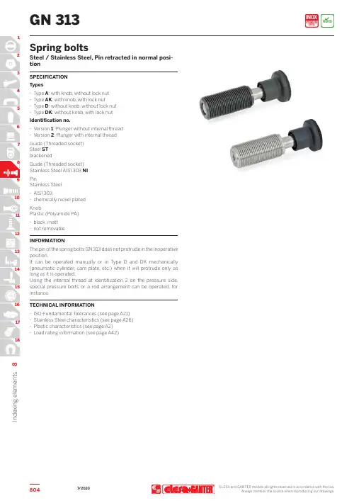
ELESA and GANTER models all rights reserved in accordance with the law.Always mention the source when reproducing our drawings.8048I n d e x i n g e l e m e n tsGN 313Spring boltsSteel / Stainless Steel, Pin retracted in normal posi-tionSPECIFICATION Types-T ype A : with knob, without lock nut -T ype AK : with knob, with lock nut-T ype D : without knob, without lock nut -T ype DK : without knob, with lock nut Identification no.-Version 1: Plunger without internal thread -Version 2: Plunger with internal thread Guide (Threaded socket)Steel ST blackenedGuide (Threaded socket)Stainless Steel AISI 303 NI PinStainless Steel-AISI 303-chemically nickel plated KnobPlastic (Polyamide PA) -black, matt -not removable INFORMATIONThe pin of the spring bolts GN 313 does not protrude in the inoperative position.It can be operated manually or in T ype D and DK mechanically (pneumatic cylinder, cam plate, etc.) when it will protrude only aslong as it is operated.Using the internal thread at identification 2 on the pressure side, special pressure bolts or a rod arrangement can be operated, for instance.TECHNICAL INFORMATION-ISO-Fundamental T olerances (see page A21) -Stainless Steel characteristics (see page A26) -Plastic characteristics (see page A2) -Load rating information (see page A42)7/20208058I n d e x i n g e l e m e n ts 2/2ELESA and GANTER models all rights reserved in accordance with the law.Always mention the source when reproducing our drawings.GN 313Spring boltsComplete with type index of the Indexing plungers (A, AK, D or DK)*AAKDDKWeight type A7/2020。

ContentsDescription Page 1.0 Setup ................................21.1 Before Installation .....................21.2 Installation ..........................21.2.1 DIN Rail Kits ......................21.3 Wiring ..............................21.3.1 Series Wiring Applications ...........31.3.2 Parallel Wiring Applications ..........31.4 Apply Power .........................31.5 Specifications ........................41.6 Warranty . (4)Surge Protective Device XXCNXXX302Instruction Manual IM01005029E Rev. 5Effective October 2018Installation Instructions for Eaton Surge Protective Device XXCNXXX30EATON WARNINGHAZARDOUS VOLTAGES PRESENTIMPROPER INSTALLATION OR MISAPPLICATION OF THESE DEVICES MAY RESULT IN SERIOUS INJURY TO INSTALLER AND/OR DAMAGE TO ELECTRI-CAL SYSTEM OR RELATED EQUIPMENT. READ AND UNDERSTAND ALL INSTRUCTIONS BEFORE BEGINNING INSTALLATION. PROTECTIVE EYE-WEAR SHOULD BE WORN WHENEVER WORKING AROUND HAZARDOUS VOLTAGES.NOTICEALL INSTRUCTIONS AND MEASUREMENTS MUST BE COMPLETED BY A LICENSED/QUALIFIED ELECTRICIAN IN ACCORDANCE WITH THE U.S. NATIONAL ELECTRICAL CODE, STATE AND LOCAL CODES OR OTHER APPLI-CABLE COUNTRY CODES. THE U.S. NATIONAL ELECTRICAL CODE AND STATE AND LOCAL REQUIREMENTS (OR OTHER APPLICABLE COUNTRY CODES) SUPERSEDE THIS INSTRUCTION.Catalog NumberVoltage RangeMode SVR MCOV In SCCRPeak Surge CurrentXXCN0243015 - 38 Vdc 5 - 30 Vdc L-N L-G N-G N/A N/A N/A N/A 20kAXXCN04830124 - 65 Vdc 24 - 50 Vdc L-N L-G N-G N/A N/A N/AN/A65kAXXCN12030248 - 149 Vdc 1 100 -127 Vac L-N L-G N-G 5005005001501501505kA 10kA 80kAXXCN230302150 - 300 Vdc 1128 - 230 VacL-N L-G N-G8008008002752752753kA 10kA 80kA1 UL 1449 4th Edition does not list SPD products rated less than 110 Vac or DC voltages.2UL 1449 4th Edition, UL 1283 7th Edition1.0 SetupVerify that system voltages do not exceed those listed in Section 1.5, Specifications.•All AC measurements should be completed with an RMS voltme-ter.• All DC measurements should be completed with a DC voltmeter. •DO NOT INSTALL DEVICE IF MEASURED VOLTAGE EXCEEDS MAXIMUM OPERATION LIMITS.Choose location for installation so that maximum separation can be maintained between input leads, output leads and ground leads.1.1 Before InstallationREMOVE POWER FROM ELECTRICAL SYSTEM BEFORE MOUNTING DEVICE.•These devices must be mounted within an enclosure to assure personnel safety from exposed terminals.IMPORTANTDEVICE SHOULD BE LOCATED SO THAT THE SHORTEST POSSIBLE CON-DUCTOR LENGTH MAY BE USED.•Device should be mounted to allow maximum separation between input and output wiring.•Device contains no position-oriented components and can be mounted upside down or sideways.•Device should be placed in electrical circuit so that it is the last device in the circuit before equipment to be protected.1.2 InstallationDEVICE MUST BE CONNECTED TO ELECTRICAL SYSTEM WITH A CIRCUIT BREAKER:For AC Applications•1 – Single Pole / Single Throw 40A circuit breaker. The Interrupting Rating of the Circuit Breaker Shall Not Be LessThan the Available Fault Current. Circuit Breaker Ratings of 40A, 240V/415V, 10kA Min. AIC Rating.Note: Pre-existing breaker of the rated load size may be utilized if provision for multi-conductor connections are made according to N.E.C. 110-14A.•If Neutral wire is to be utilized as NEU/HOT 2 then another circuit breaker should be provided for that phase.For DC Applications•DC units to be installed after an overcurrent protective device that is rated not to exceed 100% of the current rating of the unit.REMOVE POWER FROM ELECTRICAL SYSTEM BEFORE INSTALLING DEVICE.Mechanically mount device.•Mount device using mounting flange holes or optional DIN brack-et listed below.•Device should be mounted to allow maximum separation between input and output wiring.•Device contains no position oriented components and can be mounted upside down or sideways.•Device should be placed in electrical circuit so that it is the last device in circuit before equipment to be protected.1.2.1 DIN Rail KitsMounting bracket and foot adaptable to DIN Rail systems DIN EN 50022, DIN EN 50035 and DIN EN 50045 are available through Eaton Center and can be ordered separately.• Eaton Cat# DINRAILKIT-30ACF•Eaton Innovative Technology Cat# DINRAILKIT-30ITCF1.3 WiringNOTICEAN INSULATED GROUNDING CONDUCTOR THAT IS IDENTICAL IN SIZE AND INSULATION MATERIAL AND THICKNESS TO THE GROUNDED AND UNGROUNDED CIRCUIT SUPPLY CONDUCTORS, EXCEPT THAT IT IS GREEN WITH OR WITHOUT ONE OR MORE YELLOW STRIPES, IS TO BE INSTALLED AS PART OF THE CIRCUIT THAT SUPPLIES THE DEVICE. SEE TABLE 250-122 OF THE NATIONAL ELECTRIC CODE (NEC) REGARDING THE APPROPRIATE SIZE OF THE GROUNDING CONDUCTOR.THE GROUNDING CONDUCTOR IS TO BE GROUNDED TO EARTH AT THE SERVICE EQUIPMENT OR OTHER ACCEPTABLE BUILDING EARTH GROUND SUCH AS THE BUILDING FRAME IN THE CASE OF HIGH-RISE STEEL FRAME STRUCTURE.ANY ATTACHMENT-PLUG RECEPTACLES IN THE VICINITY OF THE DEVICE ARE TO BE GROUNDING TYPE, AND THE GROUNDING CONDUCTORS SERV-ING THESE RECEPTACLES ARE TO BE CONNECTED TO EARTH GROUND AT THE SERVICE EQUIPMENT OR OTHER ACCEPTABLE BUILDING EARTH GROUND SUCH AS THE BUILDING FRAME IN THE CASE OF HIGH-RISE STEEL FRAME STRUCTURE.3Instruction Manual IM01005029E Rev. 5Effective October 2018Installation Instructions for EatonSurge Protective Device XXCNXXX30EATON NOTICEPRESSURE TERMINAL OR PRESSURE SPLICING CONNECTORS AND SOL-DERING LUGS USED IN THE INSTALLATION OF THE DEVICE SHALL BE IDENTIFIED AS BEING SUITABLE FOR THE MATERIAL OF THE CONDUC-TORS. CONDUCTORS OF DISSIMILAR METALS SHALL NOT BE INTERMIXED IN A TERMINAL OR SPLICING CONNECTOR WHERE PHYSICAL CONTACT OCCURS BETWEEN DISSIMILAR CONDUCTORS UNLESS THE DEVICE IS IDENTIFIED FOR THE PURPOSE AND CONDITIONS OF USE.CONDUCTORS SHOULD BE TWISTED TOGETHER TO REDUCE IMPEDANCE FACTOR. EXCESSIVE WIRE LENGTH AND SHARP BENDS DEGRADE FIL-TER PERFORMANCE; THEREFORE, AVOID EXCESSIVE WIRE LENGTH AND SHARP BENDS.1.3.1 Series Wiring Applications•Connect incoming system GROUND wire to terminal labeled GND on unprotected end (labeled as LINE ).•Connect load side GROUND wire to terminal labeled GND on protected end (labeled as EQUIP ).For AC Applications•Connect incoming system NEUTRAL wire to terminal labeled NEU/HOT 2 on unprotected end (labeled as LINE ).•Connect load side NEUTRAL wire to terminal labeled as NEU/HOT 2 on protected end (labeled as EQUIP ).•Connect incoming system HOT wire to terminal labeled HOT 1 on unprotected end (labeled as LINE ).•Connect load side HOT wire to terminal labeled as HOT 1 on protected end (labeled as EQUIP ).For DC Applications•Connect incoming system NEGATIVE wire to terminal labeled NEU/HOT 2 on unprotected end (labeled as LINE ).Instruction Manual IM01005029E Rev. 5Effective October 2018Installation Instructions for Eaton Surge Protective Device XXCNXXX30EatonElectrical Sector1000 Eaton Boulevard Cleveland, OH 44122United States877-ETN-CARE (877-386-2273)© 2018 EatonAll Rights Reserved Printed in USAPublication No. IM01005029E / TBG000471October 2018Eaton is a registered trademark.All other trademarks are property of their respective owners.1.5 SpecificationsDescription RatingsAgency Approvals XXCNXXX30UL1449 4th Edition, UL1283 7th Edition Type 2 SPD Terminal ConnectionsWire clamping terminals, 10-18 AWG (UL), 10-22 AWG (CSA) Torque 12 in-lbSystem voltagesDC 5 - 38 Vdc, 24 - 65 Vdc, 48 - 149 Vdc, 150 - 300 Vdc AC 100 - 127 Vac, 200 - 230 Vac Operating Temperature -40F(-40C) to +140F(+60C)Circuit Breaker 40A, 240V/415V, 10kA Min. AIC Rating (Eaton P/N:FAZ-C40/1-NA-SP)Amps*30Input Power Frequency 50/60 HzWarranty 5 Years, 10 Years if registered on /spd RoHS CompliantYes* Amp rating is for series connection only. Parallel connection is not current dependent.Figure 7. Product Dimensions1.6 WarrantyEaton warrants these products for a period of 5 years from the date of delivery to the purchaser, 10 years if registered on /spd, to be free from defects in both workmanship and materi-als. Eaton assumes no risk or liability for results of the use of the products purchased from it, including but without limiting the gen-erality of the foregoing; (1) The use in combination with any electri-cal or electronic components, circuits, systems, assemblies, or any other materials or substances; (2) Unsuitability of any product for use in any circuit or assembly.Purchaser’s right under the warranty shall consist solely of requiring Eaton to repair, or at Eaton’s sole discretion, replace, free of charge, F .O.B. factory, and defective items received at said factory or failure to give any advice or recommendations by Eaton shall not constitute any warranty by or impose any liability upon Eaton. The foregoing constitutes the sole and exclusive liability of Eaton AND IS IN LIEU OF ANY AND ALL OTHER WARRANTIES EXPRESSED, IMPLIED OR STATUTORY AS TO THE MERCHANTABILITY , FITNESS FORPURPOSE SOLD, DESCRIPTION, QUALITY , PRODUCTIVENESS OR ANY OTHER MATTER.In no event shall Eaton be liable for special or consequential dam-ages or for delay in performance of the warranty.This warranty does not apply if the product has been misused, abused, altered, tampered with, or used in applications other than specified on the nameplate. At the end of the warranty period, Eaton shall be under no further warranty obligation expressed or implied.The product covered by this warranty certificate can only be repaired or replaced by the factory. For help on troubleshooting the Critical Protection Product, or for warranty information, call 1-800-809-2772, Option 4, sub-option 2. Repair or replacement units will be returned collect. If Eaton finds the return to be a manufacturer’s defect, the product will be returned prepaid.。

目录简介 1 快速启动 2 连接 2 供电 2 选择模拟输出模式 2 选择目标系统设置 2 选择预置 2 GNX3指南 3 前面板 3 后面板 6 开始启动7 连接7单声道7立体声8接入调音台8 S/P DIF数字输出9 供电9 GNX3的概况9 预置9 GNX3的模式10 音色库模式10 单块踏板模式10 录音模式11 脚踏开关的其他功能11 表现力踏板11 旁通11 校音器11 Jam-A-Long(即兴伴奏)/Learn-A-Lick(扒带) 12 如何运用“扒带”12 鼓机(节奏训练器)12选择样板13选择速度13选择音量13 编辑/创造预置14 前级放大器/音箱模拟14 前级放大器模型14 音箱类型14 编辑放大器模型和音箱类型14选择放大器模型/音箱类型15 调制前级放大器的参数15音箱调谐15 创造超级模型16储存超级模型16 编辑效果16储存/拷贝预置17 效果及参数19效果定义19 哇音--拾音19 压缩20 Whammy/IPS/Talker 20智能移调21精调音21移调21模拟说话22 模拟单块踏板22 均衡22 噪声门23 合唱/调制效果23合唱23镶边24相位24触发镶边25触发相位25震音25声向25颤音26旋转音箱26自动呀26呀呀27合成人声27包络发生器27精调音28移调28 延时28 混响29事例示范30选择预置30 创造超级模型30 选择绿色通道内的放大器和音箱模型30 选择红色通道内的放大器和音箱模型30 调整绿色通道内的参数31 调整红色通道内的参数31 调整音箱32 绿色通道和红色通道翘合在一起32 储存超级模型32 为预置的各通道选择模型33编辑预置33选择拾音类型34关闭压缩效果34关闭Whammy/IPS/Talker 34关闭模拟单块失真效果34调整噪声门35选择并调整合唱效果36关闭延时效果36选择并调整混响效果36储存预置37录音机38 录音机面板38 录音机设置39 录音输入39 立体声录音40 打点音轨41 速度41 预备节奏42 乐曲重复43 自动停止43 量化43 录音品质44 记忆卡数据传输到电脑上45 清洗45 如何运用SmartMedia记忆卡45 记忆卡/电脑的格式化46 如何运用GNX3上录音机录音48 在一条录音轨上录音48 运用UNDO键清洗录音轨49录音停止情况下运用UNDO功能49录音进行过程中运用UNDO功能49 目录放音50 设置放音轨的音量和声向50设置每一轨的音量50设置每一轨的声向51 多轨录音51 改变录音轨的状态51 插入和跳出52 合并录音轨52 鼓节奏轨52鼓节奏与乐曲同步53录制鼓节奏轨53 录制麦克输入信号53 录音输出配制54 运用乐曲和循环55 选择乐曲和循环55 删除乐曲和循环55 运用GNX3的脚踏开关录音55 单轨录音55录音机停止状态下运用取消功能56录音机在录音过程中运用取消功能56 多轨录音56 插入和跳出57 录制循环57 在循环中录入叠加音层58 运用量化形成无缝循环58 运用FS300踏板实现录音功能59 单轨录音59录音机停止状态下运用取消功能59录音机在录音过程中运用取消功能59 播放已录好的音轨60 多轨录音60 插入和跳出60 录制循环61 在循环中录入叠加音层61 其他功能62 表现力分配62 表现力踏板62 低频振荡器62 Amp 脚踏开关63 Control 脚踏开关63 可分配的表现力参数列表64 单块踏板效果参数64 调制效果参数65 公用功能65 模拟输出配制66 目标系统设置66 音量踏板的衔接66 V-Switch 的门限67 表现力踏板的修正67 音色库命名67 MIDI通道68 数据转存68 MIDI预置转存68 用户放大器转存69 MIDI指令的多元化69 MIDI指令的传导70 数字输出电平70数字输出配制70 重设出厂设置71 录音格式化71 GenEdit 编辑和音色库软件72附录73 预置列表73 MIDI执行对照表73 MIDI CC 列表74 规格说明75简介Digitech公司的GNX3是此类产品中最先进的吉他处理器之一。

EOS-AUTOERP平台操作说明书v30 EOS-AUTOERP平台操作说明书v3.0AUTOERP产品使用手册AUTOERP产品使用手册——文档版本 1.0文档编号:EOS -2006110901版权所有 ? 1998-2013 优时软件有限公司公司网址:杭州优时软件有限公司 ? 1998-2013 第 1页共 120 页AUTOERP产品使用手册版权申明优时软件有限公司保留在不另行通知的情况下修改“优时软件”标识是优时软件有限公司的注册商标。
This document contains confidential technical and commercial information from Eossoft Ltd, and is intended for the use of Customers or Eossoft?s partners only for the purposes of relatedprojects to Eossoft. No part of it may be reproduced or transmitted in any form or means without the written permission of Eossoft.This document and the product it describes are protected by copyright according to the applicable laws.The information in this document is subject to change without notice and describes only theproduct defined in the introduction of this documentation. Eossoft will, if necessary, explain issues,which may not be covered by the document.“Eossoft” logo is a registered trademark of Eossoft Ltd杭州优时软件有限公司 ? 1998-2013 第 2 页共 120 页AUTOERP产品使用手册第一章简介第一节引言EOS 3.0平台系统是分析并综合了国CPU要求:奔腾III 500(推荐PIII 1G或PIII 733x2,或更高) 软件要求 Windows 2000 服务器版或高级服务器版 MS SQL SERVER 7.0 Borland BDE 5.2运行环境(EOS 3.0提供) 客户操作电脑: 杭州优时软件有限公司 ? 1998-2013 第 3 页共 120 页AUTOERP产品使用手册II. 单独开发应用硬件要求CPU要求:赛扬800(推荐赛扬1G或更高)CPU要求:赛扬500(推荐赛扬800或更高) 软件要求 Windows98第二版,Windows ME,Windows 2000专业版或以上,Windows XP,Windows95,98(需要安装IE5.0以上) Borland BDE 5.2运行环境(EOS 3.0提供)第四节系统组成EOS 3.0平台系统软件由以下几部分组成:Eos.exe(客户端程序)、EosBuilder.exe(平台定制程序),LfRep.dll(报表定义模块)、EOSMSGER.dll(EOS 消息),以及其他电子秤、条码打印机支持程序等等。
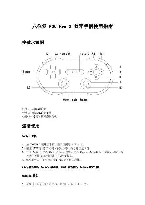
八位堂 N30 Pro 2 蓝牙手柄使用指南按键示意图*开机:按[START]键*关机:按[START]键3秒*按[START]键8秒可强制关机连接使用Switch 主机1.按 Y+START 键开启手柄,指示灯闪烁 4下 / 次。
2.按住 [PAIR] 键 2 秒进入配对状态。
指示灯快速闪烁。
3.打开 Switch 主机 Controllers 设置,进入 Change Grip/Order 界面,等待手柄连接,连接成功后指示灯进入呼吸状态。
4. 成功配对后,下次使用按START键可自动连接。
*星号键功能为 Switch 截图键,HOME 键功能为 Switch HOME 键。
Android 设备1.按住 B+START 键开启手柄,指示灯闪烁 1 下 / 次。
2.按住 PAIR 键 2 秒进入配对状态,指示灯快速闪烁。
3.打开Android设备蓝牙,搜索 8BitDo N30 Pro 2设备,点击连接,连接成功后指示灯进入呼吸状态。
4.成功配对后,下次使用按START键可自动连接。
USB 有线连接:请在开启手柄之后,用 USB 线连接设备。
Windows 设备1.按住 X+START 键开启手柄,指示灯闪烁 2 下 / 次。
2.按住 PAIR 键 2 秒进入配对状态,指示灯快速闪烁3.打开Windows 设备蓝牙,搜索 8BitDo N30 Pro 2设备,点击连接,连接成功后指示灯进入呼吸状态。
4.成功配对后,下次使用按START键可自动连接。
USB 有线连接:请在开启手柄之后,用 USB 线连接设备。
macOS 设备1.按住 A+START 键开启手柄,指示灯闪烁 3 下 / 次。
2.按住 PAIR 键 2 秒进入配对状态,指示灯快速闪烁。
3.打开 macOS 设备蓝牙,搜索 Wireless Controller 设备,点击连接,连接成功后指示灯进入呼吸状态。
4.成功配对后,下次使用按START键可自动连接。
ARM® ARM926EL-S Based32-bit MicroprocessorNuMaker-emWin-RDK-N9H30User ManualNUMAKER-EMWIN-RDK-N9H30 USER MANUALThe information described in this document is the exclusive intellectual property ofNuvoton Technology Corporation and shall not be reproduced without permission from Nuvoton.Nuvoton is providing this document only for reference purposes of NuMicro microprocessor based systemdesign. Nuvoton assumes no responsibility for errors or omissions.All data and specifications are subject to change without notice.For additional information or questions, please contact: Nuvoton Technology Corporation.Table of Contents1Overview (3)2Board Feature List (4)3Function Description (5)System Block Diagram (5)System Power Scheme (6)I/O or Jumper Description (6)3.3.1Power-on Setting (6)3.3.2SD Connector (7)3.3.3UART Interfaces (7)3.3.4USB Port (8)3.3.5RS485 Interface (9)3.3.6CAN Interface (9)3.3.7Ethernet Port (9)3.3.8JTAG Port (10)4NuMaker-emWin-RDK-N9H30 Demo Board Schematic (11)Main Block (11)Flash Memory (12)NUMAKER-EMWIN-RDK-N9H30 USER MANUALLCD Interface (13)N9H30F61I (14)Power (15)UART (16)USB (17)ETH_PHY&CAN (18)5Revision History (19)1 OverviewThe NuMaker-emWin-RDK-N9H30 demo board is N9H30 series product. Users can use theboard to develop and verify the emWin application program easily.The N9H30 series embedded the ARM®926 core for HMI applications which need highcomputing power and rich communication interfaces. The CPU can run up to 300 MHz andequipped with USB2.0 high speed device, USB2.0 high speed host, Ethernet interfaces and otherrich peripherals, such as LCD, NAND, SD, ADC, UART, SPI, I²C, I²S, CAN, RTC…etc.NUMAKER-EMWIN-RDK-N9H30 USER MANUALFigure 1-1 NuMaker-emWin-RDK-N9H30 Demo Board2 Board Feature List1. Adopted Nuvoton ARM926EJS-based MPU N9H30F61I, it can run up to 300MHz.2. NAND Flash used Winbond W29N01GV 128MB with 8-bit data bus width.3. SPI Flash used W25Q128FVSG 16MB.4. Boot selection by NAND or SPI or USB.5. One DB9 RS232 port with N9H30 UART0 for debugging.6. One DB9 RS232 port with N9H30 UART2 for user application.7. Installed SN65HVD230 transceiver for CAN bus communication.8. Installed MAX3485 transceiver for RS485 device connection.9. USB supports both HS USB2.0 device with micro USB connector and HS USB 2.0 host withtype-A connector.10. Provided one Micro-SD/TF card slot for data storage with SD memory card.11. Used 7” TFT LCD and embedded that resistive type touch panel.12. Reserved an external coin-cell socket for RTC power backup with CR2032 battery.13. Provided one10/100Mb Ethernet RJ45 port.14. Provided one buzzer device for user application.15. JTAG interface is reserved for software development advanced.16. System powered could be supplied by DC-5V adaptor or USB VBUS. NUMAKER-EMWIN-RDK-N9H30 USER MANUAL3 Function DescriptionSystem Block DiagramNUMAKER-EMWIN-RDK-N9H30 USER MANUALSystem Power Scheme NUMAKER-EMWIN-RDK-N9H30 USER MANUALI/O or Jumper Description3.3.1 Power-on SettingSW1 Function Description:NuMaker-emWin-RDK-N9H30 provided system program code booting source from NAND Flash,SPI-NOR Flash or USB. In the board we have programmed a sample emWin code to NANDflash for demonstration.About USB booting purpose is for Flash memory programming through the NuWriter of PC utilitytool, regarding the NuWriter operation please refer the user manual to get for detail.NUMAKER-EMWIN-RDK-N9H30 USER MANUALSW1-1 SW1-2Boot FromON ON booting from USB for PC communicationON OFF booting from NAND Flash OFF OFFbooting from SPI Flash3.3.2 SD ConnectorJP7: NuMaker-emWin-RDK-N9H30 provided a micro SD connector for user use what program accesses or data storage.Note. N9H30 cannot support system booting.3.3.3 UART Interfaces●CON5: One DB-9 connector for RS232 communication, the UART signals are from N9H30UART0 TXD and RXD interfaces and through the RS232 transceiver, SP3232EEN. This port isdedicated for message debugging.●CON4: One DB-9 connector for RS232 communication, the UART signals are from N9H30UART2 TXD and RXD interfaces and through the RS232 transceiver, SP3232EEN. This port isreserved for user application.3.3.4 USB Port NUMAKER-EMWIN-RDK-N9H30 USER MANUAL●CON1: This is a Micro USB connector, it is for PC communication and the signals are fromN9H30 USB port-0●CON2: This is a Type-A USB HOST connector, it is for USB devices connection and the signalsare from N9H30 USB port-1Note. CON1 VBUS can power supplied for system if connected with PC or notebook.3.3.5 RS485 Interface●J5: NuMaker-emWin-RDK-N9H30 provided a two-pin terminal connector with 3.5mm pitch forRS485 device connection.Note. MAX3485 is RS485 (half-duplex communication) transceivers and built in to NuMaker-emWin-RDK-N9H30 demo board already.3.3.6 CAN InterfaceNUMAKER-EMWIN-RDK-N9H30 USER MANUAL●CON7: NuMaker-emWin-RDK-N9H30 provided a two-pin terminal connector with3.5mm pitch forCAN bus device communication with N9H30 CAN0 port.Note. CAN transceivers,SN65HVD230 have built in to NuMaker-emWin-RDK-N9H30 demoboard already.3.3.7 Ethernet Port●CON6: NuMaker-emWin-RDK-N9H30 provided a standard RJ-45 port for 10M/100M Ethernetcommunication.Note. NuMaker-emWin-RDK-N9H30 has built in the RMII-PHY, IC+ IP101GR on board already.3.3.8 JTAG PortJ2: NuMaker-emWin-RDK-N9H30 demo board provided one male header x6 connector with pitch NUMAKER-EMWIN-RDK-N9H30 USER MANUAL2.54mm for N9H30 JTAG signals; user can make that wiring connection with Keil- ICE forsoftware development advanced.NUMAKER-EMWIN-RDK-N9H30 USER MANUAL4 NuMaker-emWin-RDK-N9H30 Demo Board SchematicMain BlockLCDLCD DGND VDD33LVSYNC LHSYNC LCD_B[7:0]LCD_G[7:0]LCD_R[7:0]LCD_CLK Y+X-Y-X+PWM VDD5V N9H30F61IN9H30F61I485_TXEN 485_TXD 485_RXD UART0_TX UART0_RX 232TXD 232RXDPH0USB0_DM USB0_DP DP1DN1RTC_XO RTC_XI nRESET 12M_XO 12M_XI VDD18VDD12VDD33DGNDLVSYNC LHSYNC LCD_B[7:0]LCD_G[7:0]LCD_R[7:0]LCD_CLKSM_D[7:0]SM_RBn SM_REn SM_CS0n SM_CLE SM_ALE SM_WEn SM_WPn SPICS SPICLK SPIWp/D2SPIDo/D0SPIDi/D1SPIHOLD/D3RTCVD Y+Y-X+X-PWM SDCd SDCmd SDD[3:0]SDCLK PHY_MDIO PHY_MDC PHY_TXEN PHY_TXD0PHY_TXD1PHY_RXD0PHY_RXD1PHY_CRSDV PHY_RXERR MAC_REFCLKCAN_TX0CAN_RX0PHY_RSTPHY_RSTFLASHFlashSM_D[7:0]SM_RBn SM_REn SM_CS0n SM_CLE SM_ALE SM_WEn SM_WPnVDD33DGNDSPICS SPICLK SPIWp/D2SPIDo/D0SPIDi/D1SPIHOLD/D3SDD[3:0]SDCmd SDCd SDCLK UARTUART485_RXD 485_TXD 485_TXEN VDD33232RXD232TXD DGND UART0_RXUART0_TX FGND VDD5VVDD5VIN USBUSB USB0_DM USB0_DPPH0VDD5VIN FGNDDN1DP1POWERPowerVDD5VVDD33VDD12VDD18RTC_XO RTC_XI 12M_XI 12M_XO nRESETDGNDRTCVD PWM 485_TXEN 485_TXD 485_RXD UART0_TX UART0_RX 232TXD TitleSize Document Number Rev Date:SheetofMAIN_BLOCK1.0N9H30F51I_HMI_DEMOB18Tuesday , Nov ember 27, 2018232RXDPH0USB0_DM USB0_DP DP1DN1RTC_XO RTC_XI nRESET 12M_XO 12M_XI VDD18VDD12VDD33VDD33DGNDDGNDVDD5VIN FGND VDD5VFGNDVDD5VIN VDD5VLVSYNC LHSYNC LCD_B[7:0]VDD5VLCD_G[7:0]LCD_R[7:0]LCD_CLK DGND VDD33SDCd SM_D[7:0]SDCmd SM_RBn SM_REn SDD[3:0]SM_CS0n SM_CLE SM_ALE SM_WEn SM_WPn SDCLK ETH_PHY&CANETH_PHY&CANPHY_RXD0PHY_RXD1PHY_CRSDV PHY_MDIO PHY_MDC PHY_RXERRMAC_REFCLK PHY_TXEN PHY_TXD0PHY_TXD1VDD33DGNDCAN_TX0CAN_RX0FGND PHY_RSTPHY_MDIO SPICS PHY_MDC SPICLK PHY_TXEN SPIWp/D2SPIDo/D0SPIDi/D1PHY_TXD1PHY_TXD0PHY_RXD1PHY_RXD0PHY_CRSDV PHY_RXERR MAC_REFCLK CAN_TX0CAN_RX0SPIHOLD/D3DGNDVDD33RTCVD Y+VDD33DGND FGNDY-X+X-NUMAKER-EMWIN-RDK-N9H30 USER MANUALFlash MemoryNAND FLASHVDD33VDD33SM_D[7:0]VDD33SM_D[7:0]U1W29N01GVNC 1NC 2NC 3NC 4NC 5NC 6R/B 7RE 8CE 9NC 10NC 11Vcc 12Vss 13NC 14NC 15CLE 16ALE 17WE 18WP 19NC 20NC 21NC 22NC 48NC 47NC 46NC 45I/O744I/O643I/O542I/O441NC 40NC 39NC 38Vcc 37Vss 36NC 35NC 34NC 33I/O332I/O231I/O130I/O029NC 28NC 27NC 23NC 24NC 26NC25DGND R110KSM_D7SM_RBn SM_D6SM_REn SM _RBn SM_CS0nSM_REn SM_D5SM_CS0nSM_D4SM_CLE SM_ALE VDD33SM_WEn SM_ALE SM_CLE VDD33SM_WPnSM_WEn SM_D3R1410K SM_WPnSM_D2SM_D1R310K/N O PSM_D0VDD33VDD33C B10.1uFDGNDTitleSize Document Number Rev Date:SheetofFlash1.0N9H30F51I_HMI_DEMOA 38Tuesday , Nov ember 27, 2018SPICS SPICLK SPIWp/D2SPIDo/D0SPIDi/D1SPIHOLD/D3C210UF/25V C0805U2SRV05-4SOT23-6CH46CH23CH34Vn 2Vp 5CH11U3SRV05-4SOT23-6CH46CH23CH34Vn 2Vp 5CH11R2SDVD33VDD33DAT3C11UFC0603VDD33DGNDCB20.1uFSDD[3:0]SPI FalshR1810K JP7B8502A-13SB-HPA (T-Flash Card)DAT21DAT32CMD 3VDD 4CLK 5VSS 6DAT07DAT18CD9GND10GND 11GND 12GND 13R1910KSDD[3:0]R2010KR647SDD2R747DGND SDCmdSDD3DAT2R847U5W25Q128/CS 1Do/D12Wp/D23GND 4Di/D05CLK 6Hld/D37VCC 8SDVD33SDCmdSPICS CMD SPIHOLD/D3SPIDi/D1R1047SPIWp/D2SDCLKSPIDo/D0SPICLK CLK SDVSS R1347C3NC SDD0R1547DAT0L1600次@100M H ZL0603SDCdSDD1R1647DAT1SDVSSCDSDCdVDD33VDD33R1710KR510K DGNDVDD33R910KVDD33R410K R110DGND TF CARDVDD33R1210K SDCLKSDVD33DAT2CLKSDVSSDAT3CMDCDSDVD33DAT1SDVSS DAT0LCD InterfaceNUMAKER-EMWIN-RDK-N9H30 USER MANUALN9H30F61IU8N9H30F61I00000000000000000000000000000000000000000000000000000000000000000000000000000000000000000000000000000000000000NUMAKER-EMWIN-RDK-N9H30 USER MANUALPowerTitleSize Document Number Rev Date:SheetofPower1.0N9H30F51I_HMI_DEMO A 68Tuesday , Nov ember 27, 2018VDD5VL10 4.7uHVDD33U9ZT7103TTSOT-25EN1GND 2SW 3Vin 4FB5C32470pFCB220.1uFDGND R50680KDGNDDGND R52150K32768H z C r y s t a l12M H z C r y s t a lDGNDDGNDVDD5VX1TXC-9H T9 SMD 32.768KHz 30ppmR5310KRTC_XI RTC_XOC3815pFC3915pFVDD5VL12 4.7uHU11ZT7103TTSOT-25EN1GND 2SW 3Vin 4FB5DGNDDGNDC361nFDGND R54120KC40NC DGNDR55120KDGND R561MDGND12M_XI12M_XO DGNDX212MHz CRYSXIN1GND 2GND 4XOUT 3VDD5VC4215pFR5710KC4515pFDGND VDD5VDGNDL13 4.7uHDGNDU12ZT7103TTSOT-25EN1GND 2SW 3Vin 4FB5DGNDC441nFC46NCDGND R58200KDGNDR59100KDGNDDGNDDGNDC3510UF/25V C0805C4110UF/25V C0805C4710UF/25V C0805C3710UF/25V C0805C4310UF/25V C0805VDD12JP8SIP/2P SW_PB2_B1_SMD12VDD18C3410UF/25V C0805VDD5VVDD33DGNDVDD12VDD18L18600次@100MHZL0603RTC_XIRTC_XO12M_XI12M_XOU10TLV809GND1/RESET 2VDD3R E S E TC 330.1uFVDD33R51R490DGNDL11600次@100MHZL0603nRESETnRESETDGNDRTCVDD12RB521S-3012VDD33D13RB521S-3012BT1CR2032BAT\CR2032-4-2\smdCB230.1uF DGNDDGNDRTCVDD9SMAJ5.0CAD10SMAJ5.0CAD11SMAJ5.0CALED1GREEN LED 12R601KVDD33DGNDNUMAKER-EMWIN-RDK-N9H30 USER MANUALUARTRS485RS232000000000000RS23200000NUMAKER-EMWIN-RDK-N9H30 USER MANUALUSBU S B 0 D e v i c eR6920K USB0_DMR704.7USB0_DPR714.7PH0UDO1UDO0PH0FGNDR7239KFGNDFGNDVDD5VINTitleSize Document Number Rev Date:SheetofUSB1.0N9H30F51I_HMI_DEMOA 88Tuesday , Nov ember 27, 2018D1-D1+FGNDFGNDVDD5VINVDD5VIN CON1USB MICRO-AB RECEP.MICRO_USB_AB_LSVBUS 1D-2D+3GND5ID 4Shield 6Shield 7Shield 8Shield9C 751uFL15600次@100MHZL0603D161N4148VBUSVDD5VINUSB HostL16600次@100M H Z 12CON2USB TYPE-A B4P_ATYPEVBUS 1D-2D+3GND4Shield 5Shield6VBUS1DN1R73 4.7DN1C 570.1uFDP1R74 4.7DP1L17600次@100M H Z12FGND FGNDC5610UF/25V C0805L14600次@100M H Z 12U16SRV05-4SOT23-6C H 46C H 23C H 34V n 2V p 5C H 11U17SRV05-4SOT23-6C H 46C H 23C H 34V n 2V p 5C H 11F1FUSE(6V/1A)NUMAKER-EMWIN-RDK-N9H30 USER MANUALETH_PHY&CANR940R0603VDD33DGND U20SN65HVD230SO-8D 1GND 2VCC 3R4Rs 8CANH 7CANL 6Vref5CAN_TX0DGND CAN_RX0CB270.1uF C0603DGNDCON7SIP\2P\5MM SIP/2P_3.5MM12CAN_TX0CAN_RX0R96120R0603CAN0H CAN0L50MClkiPHY_RST Phy AD3CRS TitleSize Document Number Rev Date:SheetofETH_PHY&CAN1.0N9H30F51I_HMI_DEMOB 28Tuesday , Nov ember 27, 2018CON6RJ-45 8P8C_LED R/ARJ45\8P\JA\LEDTX+1TX-2RX+3NC 4NC 5RX-6NC 7NC8Shield 13Shield 14LED-9LED+10LED-11LED+12R841M R0603CT210uFR8975R78Col Col C760.01uF/2KVCK05CRSCT310uFC657pF C0603C640.1uFR9075R795.1K R0603R835.1K R0603C637pF C0603R8210K R0603C62N.C.C0603R850R0603R9275C670.1uFC660.01uF U19TS8121CTX+16TX-14NC 13TD-3TD+1RD+6RD-8NC5RX-9RX+11CT 2NC 4CT 7CT 10NC12CT 15R766.19K +/-1%R0603U18IP101GR TxEr/FxSD 1Xi 2Xo 3Col/RMII 4TxEn 5TxD36TxD27TxD18TxD09TxClk/50MClki 10LED0/Phy AD011LED3/Phy AD312IOVDD 13RxClk/50M_Clko 14RxD315RxD216TestOn 24MDIO 23MDC 22RxEr/Int3221CRS/LEDMod 20RxDV/CRS_DV 19RxD018RxD117nRst 32AVD3331MDiTp 30MDiTn 29RegOut 28MDiRp 27MDiRn 26Iset 25R88330R0603RMii0TxD1RMii0TxD0RMii0MDC R9175RMii0RxD1RMii0RxD0CT110uFRMii0MDio RMiiRxErr RMii0CRSDV MDI_TN MDI_TP RMii0TxEn C680.01uFMDI_RP MDI_RNX325MHz CRYSXIN1GND 2GND 4XOUT 3EthX1R95 5.1KCB250.1uF R770R0603CT410uF C690.01uF/2KVR86330R0603EthX0R8110K R0603EthX1R805.1K R0603EthX0R935.1KCB260.1uF R870R0603PHY_RXD0Phy AD0PHY_MDIO PHY_CRSDV PHY_RXD1MAC_REFCLKPHY_RXERR PHY_MDCPHY_TXD0PHY_TXEN DGNDVDD33PHY_TXD1Phy AVD33PHY_RSTRegOut DGNDPhy IOVD33RegOutDGNDDGNDDGNDDGND DGNDDGNDVDD33DGNDPhy AVD33Phy IOVD33DGNDDGND Phy IOVD33DGNDVDD33VDD33DGNDDGNDFGNDDGNDFGNDDGNDDGND RMii0MDio RMiiRxErr DGND FGND VDD33VDD33DGNDFGND50MClki RMii0Ref Clk FGNDR10210K R0603PHY_RST RMii0CRSDV C771uF C0603DGNDRX+TX-RX-TX+MDI_TNMDI_TP Phy AD3Phy AD3MDI_RP MDI_RNE t h e r n e t T P o r tPhy AD0Phy AD05 Revision HistoryDate Revision Description2018.10.03 1.00 1. Initially.2018.11.27 2.00 1. PCB version 2.1, supports Ethernet and CAN2021.03.26 2.01 1. Rename NuMaker-emWin-RDK-N9H30Important NoticeNuvoton Products are neither intended nor warranted for usage in systems or equipment, any malfunction or failure of which may cause loss of human life, bodily injury or severe property damage. Such applications are deemed, “Insecure Usage”.Insecure usage includes, but is not limited to: equipment for surgical implementation, atomic energy control instruments, airplane or spaceship instruments, the control or operation of dynamic, brake or safety systems designed for vehicular use, traffic signal instruments, all types of safety devices, and other applications intended to support or sustain life.All Insecure Usage shall be made at customer’s risk, and in the event that third parties layclaimsto Nuvoton as a result of customer’s Insecure Usage, custome r shall indemnify thedamages and liabilities thus incurred by Nuvoton.NUMAKER-EMWIN-RDK-N9H30 USER MANUAL。
aigot30耳机说明书
关于aigot30耳机参数配置
真正无线连接(TWS)实现无线立体声,左右声道分离,HIFI音效。
左右耳均具有完整蓝牙功能,可单独使用,也可以成对使用。
关于aigot30耳机使用步骤与特别说明
开启充电盒开关(蓝灯或红灯亮起)
打开充电盒上盖取出耳机,耳机自动开机配对(重要提示:打开充电盒之前开启充电盒开关,是耳机自动开机的前提)
与其他设备配对:打开手机或其它设备蓝牙设置,搜索蓝牙名点击链接蓝牙
耳机放入充电盒进入充电模式,耳机自动关机
关于aigot30耳机触摸功能说明
左耳、右耳触摸位置,轻触1下接听电话,左右耳机连触2下音量减,右耳耳机连触2下音量加,左耳连按3下下一曲,右边连按3下上一曲,长按3秒Siri功能,长按5秒开关机,来电时两个耳机同时报号。
关机后再开机,耳机自动连回手机
关于aigot30耳机注意事项
请勿暴力对待本产品,也不要用重物挤压,远离高温高湿环境。
远离WIFI,路由器以及其它高频发射设备,这样会影响本机的
信号接收,造成声音的卡断及断连。
八位堂NES30 Pro无线蓝牙手柄使用指南NES30 Pro 无线蓝牙手柄是一款便携型全键位手柄,NES风格复古设计搭配真空刃呼吸灯的炫酷外形;适合格斗, 射击和动作游戏, 特别是玩模拟器怀旧游戏;配备全功能按键以及双模拟摇杆,蓝牙、USB 双连接可支持多平台设备;多种超级模式轻松驾驭不同的使用环境和游戏;独立 MCU + 可刷写 Flash 芯片支持固件升级。
按键示意图蓝牙连接安卓设备1.按住 [POWER] 键 2 秒开启 [手柄模式] ,蓝色指示灯闪 1 下/次2.Android 设备打开蓝牙,搜索 [8Bitdo NES30 Pro] 设备,点击连接,连接成功后指示灯为呼吸状态iOS 设备1.将系统输入法设置为 [English]2.按住 [POWER+A] 键 2 秒开启 [iCade 模式],蓝色指示灯闪 3 下/次3.iOS 设备打开蓝牙,搜索 [8Bitdo NES30 Pro] 设备,点击连接,连接成功后指示灯为呼吸状态Windows 设备1.按住 [POWER]键 2 秒开启 [手柄模式] ,蓝色指示灯闪 1 下/次2.Windows 设备打开蓝牙,搜索 [8Bitdo NES30 Pro] 设备,点击连接,连接成功后指示灯为呼吸状态MacOS 设备1.按住 [POWER] 键 2 秒开启 [手柄模式] ,蓝色指示灯闪 1 下/次2.MacOS 设备打开蓝牙,搜索 [8Bitdo NES30 Pro] 设备,点击连接,连接成功后指示灯为呼吸状态关机:按住 [POWER] 键2秒关闭手柄,指示灯熄灭USB 连接(Windows / macOS / Android)1.按住 [POWER] 键2 秒开启 [手柄模式]2.将附带的 Micro USB 线连接手柄,另一端插入 PC3.等待设备识别手柄后即可使用*USB 连接时,可忽略指示灯状态;部分 Android 设备可能需要使用 OTG 转接线连接超级模式与扩展固件特别开发多种[扩展固件],可支持更多不同的设备和不同的游戏;通过升级[扩展固件]即可获取更多[超级模式][超级模式]请访问:/nes30pro/Extend-firmware.html 了解更多升级固件(Windows / MacOS)请访问 /nes30pro/Firmware.html了解更多电源NES30 Pro 内置 480 mAh 可充电式锂聚合物电池,可带来最高长达 18 小时的使用时间; 您可以使用配备的 Micro USB 线进行充电,充电时间约 1 ~ 2 小时,充电完成后绿色指示灯熄灭,蓝色灯闪烁。