CL-01A型 步进电机控制器说明书
- 格式:pdf
- 大小:382.15 KB
- 文档页数:13
步进电机,伺服电机可编程控制器KH-01使用说明一、系统特点●控制轴数:单轴;●指令特点:任意可编程(可实现各种复杂运行:定位控制和非定位控制);●最高输出频率:40KHz(特别适合控制细分驱动器);●输出频率分辨率:1Hz;●编程条数:99条;●输入点:6个(光电隔离);●输出点:3个(光电隔离);●一次连续位移范围:—7999999~7999999;●工作状态:自动运行状态,手动运行状态,程序编辑状态,参数设定状态;●升降速曲线:2条(最优化);●显示功能位数:8位数码管显示、手动/自动状态显示、运行/停止状态显示、步数/计数值/程序显示、编辑程序,参数显示、输入/输出状态显示、CP脉冲和方向显示;●自动运行功能:可编辑,通过面板按键和加在端子的电平可控制自动运行的启动和停止;●手动运行功能:可调整位置(手动的点动速度和点动步数可设定);●参数设定功能:可设定起跳频率、升降速曲线、反向间隙、手动长度、手动速度、中断跳转行号和回零速度;●程序编辑功能:可任意插入、删除可修改程序。
具有跳转行号、数据判零、语句条数超长和超短的判断功能;●回零点功能:可双向自动回到零点;●编程指令:共14条指令;●外操作功能:通过参数设定和编程,在(限位A)A操作和(限位B)B操作端子上加开关可执行外部中断操作;●电源:AC220V(电源误差不大于±15%)。
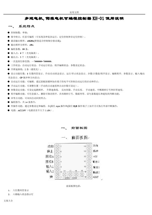
一、前面板图前面板图包括:1、八位数码管显示2、六路输入状态指示灯3、三路输出状态指示灯4、 CP脉冲信号指示灯5、 CW方向电平指示灯6、按键:共10个按键,且大部分按键为复合按键,他们在不同状态表示的功能不同,下面的说明中,我们只去取功能之一表示按键。
后面板图及信号说明:后面板图为接线端子,包括:1、方向、脉冲、+5V为步进电机驱动器控制线,此三端分别连至驱动器的相应端,其中:脉冲————步进脉冲信号方向————电机转向电平信号+5V————前两路信号的公共阳端CP、CW的状态分别对应面板上的指示灯2、启动:启动程序自动运行,相当于面板上的启动键。

深圳市雷赛智能控制股份有限公司地址:深圳市南山区南山区学苑大道1001号南山智园A3栋11楼邮编:518055网址:CL57闭环步进驱动器使用说明书版权所有不得翻印【使用前请仔细阅读本手册,以免损坏驱动器】深圳市雷赛智能控制股份有限公司1 2目 录一、产品简介............................................................................................................. 2 1. 概述 ........................................................................................................................ 2 2. 技术特点 ................................................................................................................ 2 3. 应用领域 ................................................................................................................ 3 二、电气、机械和环境指标 ..................................................................................... 3 1. 电气指标 ................................................................................................................ 3 2. 使用环境及参数 .................................................................................................... 3 3. 机械安装图 ............................................................................................................ 4 4. 加强散热方式 ........................................................................................................ 4 三、驱动器接口和接线介绍 ..................................................................................... 5 1. 接口定义 ................................................................................................................ 5 2. 控制信号接口电路 ................................................................................................ 7 3. 控制信号时序图 .................................................................................................... 8 4. 控制信号模式及细分设置 .................................................................................... 9 5. 编码器接线 ............................................................................................................ 9 6. 串口接线 .............................................................................................................. 10 四、拨码开关设定................................................................................................... 10 五、驱动器参数设置............................................................................................... 11 六、典型应用接线................................................................................................... 14 1. 闭环步进电机编码器引线定义 .......................................................................... 14 2. 闭环步进电机线定义 .......................................................................................... 14 雷赛产品保修条款 (15)CL57闭环步进驱动器一、产品简介 1、概述CL57是雷赛公司基于十几年步进与伺服研发经验开发成功的一款新型闭环步进驱动器,采用最新专用电机控制DSP 芯片和应用前功角闭环控制技术,从而彻底克服开环步进电机丢步的问题,轻载状态下能明显提升电机的高速性能、降低电机的发热程度和减小电机的振动,从而提升机器的加工速度和精度以及降低机器的能耗。

混合式步进电机(BYG系列)步进电机是一种将电脉冲信号转换成角位移的执行元件,可在宽广的范围内调速。
在负载能力范围内,其输出转角定位精度无积累误差,特别适合于开环数控系统。
混合式步进电机是一种兼有反应式和永磁式两种步进电机优点的新型电机,国外主流品种,国内也已大面积取代反应式步进电机成为市场热点。
五相及三相混合式步进电机因其分辨率小,精度高,低频无振荡,高频力矩大,而成为混合式步进电机中的佼佼者。
一、特点本公司自行研制的BYG系列混合式步进电机,结合国内外先进技术而设计,采用优质材料和精良工艺制造,实行严格的质量管理,在国内处于领先水平,可与国外同类电机媲美。
其显著特点是:1、采用优质冷轧高矽片,无机壳铆压,大大改善了磁性能;电机体积小,驱动电流和功耗小,力矩大,运行频率高,动态特性好,温升低。
本公司产品的静态及动态力矩较国内同类产品高出一档次。
2、有良好的内部阻尼特性,运行平稳,无明显低频振荡区。
3、造型美观,结构牢固,噪音低,可靠性高,使用寿命长。
4、品种齐全,系列完整,可满足各种使用场合。
正广泛应用于各类机床,切割机,轻工、印刷、包装、纺织、环保、医疗机械,航空航海设备,汽车,机器人,舞台灯光控制、广告设备,电脑绣花机等自动控制领域。
二、型号含义110 BYG 5 5 0 1 WB特殊型或派生号,以字母表示,无此项时为基本型(Z为增强型,WB为五边型,D为双轴伸,其它为派生型)规格号:1号转子齿数:50齿相数:5相混合式步进电机(FHB为方形混合式步进电机)机座号:外径φ110mm三、产品系列及性能参数1.方形电机系列2.圆形电机系列注:1、打 * 者为正在开发的新产品,可供期货;型号后有“Z”者为增强型。
2、二相电机为四引出线,四相电机为八引出线,除出线方式不同外,其余参数性能完全一样,配本公司驱动电源时用二相电机。
四相电机可改接成二相电机,有串联、并联及单极性三种接法,按并联接法时,相电流应加倍,四相电机用并联接法时,高速性能要优于其它接法。

申菱门机NSFC01-01A型目录1.注意事项分类22.端子定义53.按键名称和基本操作54.接线图65.快速调试76.门机运行信号确认77.开关门曲线说明88.功能参数表109.功能参数详细说明表1110. 故障代码说明162、端子定义端子名称电缆线号(颜色)端子功能说明L / N / 接地褐色/蓝色/黄绿单相交流电源输入端子OP 2# 开门命令常开输入(NO)CL 3# 关门命令常开输入(NO)OPI --* 开门到位常闭输入(NC)CLI --* 关门到位常闭输入(NC)DECO --* 开门减速常闭输入(NC)DECC --* 关门减速常闭输入(NC)ENI 消防功能端子GNDE 1# 开关门输入公共端(COM) U / V / W U/V/W 电机接线端子OPO 5# 开门到位输出CMO 4# 开门到位输出公共端CLO 6# 关门到位输出CMC 4# 关门到位输出公共端Y-1 备用多功能输出Y-2 多功能输出公共端注: [1] --*为控制器内部接线,不在6芯控制电缆线内。
[2] 信号输入端子请连接无电压接电信号或开路集电极信号。
信号端电压为+24VDC ,输入公共端GNDE为负。
3、按键名称和基本操作3.1 按键名称键名基本功能说明MODE(模式)键切换模式000 、参数p、参数d 和参数nSET(设定)键进入菜单以及存储数据(上升)键修改数据以及用于设定正转方向(下降)键修改数据以及用于设定反转方向RUN(运行)键使电梯门控制器运行STOP(停止)键使电梯门控制器停止运行4、接线图图2:控制器接线图注意: 在配接开/关门到位输出电缆线时,要确认门控制器输出的逻辑状态与控制柜接收的逻辑相符,门控制器的出厂状态是常闭输出。
用户要根据主控制柜实际情况选择到位输出的逻辑状态。
更改逻辑状态见参数P16、P17,置0为常开输出,置1为常闭输出。
5、快速调试门机出厂前已完成控制器内部接线和所有功能调试,用户可根据实际情况按以下步骤 1-3 项调节开/关门曲线即可。
步进电机,伺服电机可编程控制器KH-01使用说明一、系统特点●控制轴数:单轴;●指令特点:任意可编程(可实现各种复杂运行:定位控制和非定位控制);●最高输出频率:40KHz(特别适合控制细分驱动器);●输出频率分辨率:1Hz;●编程条数:99条;●输入点:6个(光电隔离);●输出点:3个(光电隔离);●一次连续位移范围:—7999999~7999999;●工作状态:自动运行状态,手动运行状态,程序编辑状态,参数设定状态;●升降速曲线:2条(最优化);●显示功能位数:8位数码管显示、手动/自动状态显示、运行/停止状态显示、步数/计数值/程序显示、编辑程序,参数显示、输入/输出状态显示、CP脉冲和方向显示;●自动运行功能:可编辑,通过面板按键和加在端子的电平可控制自动运行的启动和停止;●手动运行功能:可调整位置(手动的点动速度和点动步数可设定);●参数设定功能:可设定起跳频率、升降速曲线、反向间隙、手动长度、手动速度、中断跳转行号和回零速度;●程序编辑功能:可任意插入、删除可修改程序。
具有跳转行号、数据判零、语句条数超长和超短的判断功能;●回零点功能:可双向自动回到零点;●编程指令:共14条指令;●外操作功能:通过参数设定和编程,在(限位A)A操作和(限位B)B操作端子上加开关可执行外部中断操作;●电源:AC220V(电源误差不大于±15%)。
一、前面板图前面板图包括:1、八位数码管显示2、六路输入状态指示灯3、三路输出状态指示灯4、 CP脉冲信号指示灯5、 CW方向电平指示灯6、按键:共10个按键,且大部分按键为复合按键,他们在不同状态表示的功能不同,下面的说明中,我们只去取功能之一表示按键。
后面板图及信号说明:后面板图为接线端子,包括:1、方向、脉冲、+5V为步进电机驱动器控制线,此三端分别连至驱动器的相应端,其中:脉冲————步进脉冲信号方向————电机转向电平信号+5V————前两路信号的公共阳端CP、CW的状态分别对应面板上的指示灯2、启动:启动程序自动运行,相当于面板上的启动键。
目录1.产品概述 (1)2.应用环境及安装 (2)2.1应用环境要求 (2)2.2驱动器安装尺寸 (3)3.驱动器端口和接线 (4)3.1端口功能说明 (4)3.2电源输入 (4)3.3编码器连线 (4)3.3电机连线 (5)3.5控制信号连线 (5)3.5.1PUL、DIR端口 (5)3.5.2ENA端口 (5)3.5.3ALM端口 (5)3.5.4控制信号接线实例 (6)3.6RS232串口 (7)4.拨码及运行参数设置 (7)4.1每转脉冲设置 (7)4.2电机方向选择 (8)4.3脉冲滤波功能选择 (8)4.4脉冲模式选择 (8)4.5带宽选择 (8)5.驱动器工作状态LED指示 (8)6.常见问题及对策 (9)附录A.保修条款 (9)1.产品概述感谢您选择CL系列数字式步进伺服驱动器。
步进伺服,是在普通开环步进电机的基础上,结合位置反馈和伺服算法形成的高速、高扭矩、高精度、低振动、低发热、不丢步的步进伺服方案。
CL系列步进伺服驱动器,基于TI公司全新32位DSP处理芯片的平台,利用伺服驱动器中磁场定向(FOC)和矢量弱磁控制算法设计,具有全方位超越普通步进的性能表现。
内置PID参数调节功能,使电机更好的满足不同种类负载的应用;内置弱磁控制算法,使电机高速时磁场特性减弱,保持动力;内置电流矢量控制功能,使电机具有伺服的电流特性,发热低;内置微步指令算法,使电机运行各速度段时保持平稳、低振动;内置4000pulse分辨率的编码器反馈,使定位精度提高,绝不丢步。
总之,结合步进电机特性的伺服控制方案使得CL系列步进伺服驱动器能更好的发挥步进电机的性能,可替代相同功率的伺服应用,是自动化设备最优性价比的新选择。
CL57驱动器可通过拨码开关和调试软件设置细分及其他参数,具有电压、电流、位置等保护功能,增添报警输出接口,其输入输出信号均采用光电隔离。
供电电源24–60VDC控制精度4000Pulse/r脉冲模式方向&脉冲、CW/CCW双脉冲电流控制伺服矢量控制算法细分设置拨码开关设定,16种选择(或调试软件设定)速度范围常规1200~1500rpm,最高4000rpm共振抑制自动计算共振点,抑制中频振动PID参数调节调试软件调整电机PID特性脉冲滤波2MHz数字信号滤波器报警输出过流、过压、位置错误等报警输出希望我们优异性能的产品,可以帮您出色的完成运动控制项目。
单轴步进电机控制器采用程序固定、 数值修改的方法进行编程, 其编程、 操作非常简单, 同时能接收和控制外部信号或动作。
可与步进电机驱动器、 步进电机组成一个控制系统,能控制一台步进电机作单向、定长、定速单动作运行,可广泛应用于纺织、塑料、造纸、印刷、包装等行 业的各种定长控制的领域。
STK01功能简介☆ 具有正反向手动调节功能,并且可在运行过程中加速,减速,并且可以储存加速,减速后的参数。
☆ ☆ ☆ ☆ ☆ ☆启动频率,运行频率,运行长度可设定 9 条升降曲线选择 手动启动或外部输入信号控制电机运行 双排数码显示,可显示当前的运行速度和运行长度 延时功能 直接 AC 220V 输入,无需再加电源。
显示功能在功能设定时显示功能名 上排 4 位数码 下排 4 位数码 OUT 绿发光管 PHO 黄发光管 NEAR 红发光管 在运行状态时显工作模式字符 在功能设定时显示设定值 在运行状态时显示运行速度或频率 继电器状态指示 输入 INA 状态指示(外部触发信号) 电机运转状态指示(电机运转时闪烁)操作方法按设定键 进入功能设定状态,如图所示:单轴步进电机控制器 具体功能如下:脉冲数设定:上排显示‘L’, 下排显示设定脉冲值, 按 按或键,增加或减少到设定所需值,确定此值并进入下一参数设定。
(最大 9999 个脉冲,可以定制 4x9999,20x9999) 或 键,增加或减少到设运行速度设定:上排显示 PPS, 下排显示设定最高运行速度,按 定所需值,按 确定此值并进入下一参数设定。
延时时间设定: 上排显示 CL, 下排显示设定延时时间最大 9.999S, 在自动模式 (AUTO) 时有效, 按 或 键,增加或减少到设定所需值,按 确定此值并进入下一参数设定。
加速度设定:上排显示 RISE , 下排显示为 1 至 9 中的一个, 步进电机在一定速度(一定负载或惯性下)不能直接起动,故要从较小的速度起动并加速至设定运行速度,加速度设定为 1 时,加速度最大 ,当为 9 时, 加速度最小,此设定值应根据负载轻重和最高运行速度合理选择,使系统运行又快又稳。
Instruction ManualStep Motor Controller – CC-Link(24 VDC Servo)Series JXCM1##-#The intended use of the step motor controller is to controlthe movement of an electrical actuator whilst connectedto the CC-Link protocol.These safety instructions are intended to prevent hazardous situations and/or equipment damage. These instructions indicate the level of potential hazard with the labels of “Caution,” “Warning” or “Danger.”They are all important notes for safety and must be followed in additionto International Standards (ISO/IEC) *1), and other safety regulations.IEC 60204-1: Safety of machinery - Electrical equipment of machines. (Part 1: General requirements)ISO 10218-1: Robots and robotic devices - Safety requirements for industrial robots - Part 1: Robots.•Refer to product catalogue, Operation Manual and Handling Precautions for SMC Products for additional information.• Keep this manual in a safe place for future reference.Caution Caution indicates a hazard with a low level of risk which, ifnot avoided, could result in minor or moderate injury.Warning Warning indicates a hazard with a medium level of riskwhich, if not avoided, could result in death or serious injury.Danger Danger indicates a hazard with a high level of risk which, ifnot avoided, will result in death or serious injury.Warning•Always ensure compliance with relevant safety laws and standards.•All work must be carried out in a safe manner by a qualified person in compliance with applicable national regulations.2.1 General specificationsItem SpecificationsCompatible motor Step motor (servo 24 VDC)Power supply voltage24 VDC +/-10%(motor drive control, stop, lock brake release).Current consumption 3A (Peak 5A) maximumCompatible encoderBattery-less absolute encoder (resolution: 4096 pulses / rotation)Serial communication RS485Locking Unlocking terminal (applicable to non-exitationmagnetizing lock)Cable length Actuator cable: 20 m maximum Cooling method Air-cooling type Operatingtemperature0o C to 55o C (No freezing) Storage temperature -10o C to 60o C (No freezing) Operating humidity 90% RH or less (No condensation)Insulation resistance50 MΩ (500 VDC)between the external terminals and caseWeight170 g (Direct mounting type)190 g (DIN rail mounting type)2.2 CC-Link specificationsWarningSpecial products (-X) might have specifications different from thoseshown in this section. Contact SMC for specific drawings.3 Name and function of individual parts4 Installation4.1 InstallationWarning•Do not install the product unless the safety instructions have been readand understood.•Design the installation so that the temperature surrounding thecontroller is 55o C max. Leave enough space between the controllersso that the operating temperature of the controllers remains within thespecification range.•Mount the controller vertically with 30 mm minimum space on the topand bottom of the controller as shown below.•Allow 60 mm minimum space between the front of the controller and adoor (lid) so that the connectors can be connected and disconnected.4.2 Mounting•The controller can be direct mounted (model JXCM17#) using screwsor mounted on a DIN rail (model JXCM18#).•When using DIN rail mounting, hook the controller on the DIN rail andpress the lever down to lock it.CautionIf the mounting surface for the controller is not flat or is uneven, excessivestress may be applied to the enclosure, which can cause failure. Be sureto mount on a flat surface.4.3 EnvironmentWarning•Do not use in an environment where corrosive gases, chemicals, saltwater or steam are present.•Do not use in an explosive atmosphere.•Do not expose to direct sunlight. Use a suitable protective cover.•Do not install in a location subject to vibration or impact in excess ofthe product’s specifications.•Do not mount in a location exposed to radiant heat that would result intemperatures in excess of the product’s specifications.•Avoid mounting the controller near a vibration source, such as a largeelectromagnetic contactor or circuit breaker on the same panel.•Do not use in an environment with strong magnetic fields present.4.4 WiringCaution•Do not perform wiring while the power is on.•Confirm proper insulation of wiring.•Do not route wires and cables together with power or high voltagecables.•Keep wiring as short as possible to prevent interference fromelectromagnetic noise and surge voltage.•Do not use an inrush current limited type of power supply for thecontroller.•Do not connect multiple wires to one connector terminal.Power Supply ConnectorWire the power supply cable to the power supply plug connector, theninsert it into connector PWR on the controller.•Use special screwdriver (Phoenix Contact No. SZS0.4×2.0) to open /close lever and insert the wire into the connector terminal.•Applicable wire size: 20 AWG (0.5 mm2).PinNo.Terminal Function Description1 C24V Power supply (+) Positive control power.2 M24V Motor power (+)Positive power for theactuator motor suppliedvia the controller.3 EMG Stop (+)Positive power foremergency stop signal4 0V Common power (-)Negative common power forM24V, C24V, EMG and LKRLS.5 - NC N/A6 LK RLS Unlocking (+)Positive power for lockrelease.30 mm min. (Direct mounting)50 mm min. (DIN rail mounting)30 mm minimumControllerORIGINAL INSTRUCTIONS②③④⑤⑥⑦⑧⑪①⑨Power Supply Wire specificationsPrepare the wiring according to the following specifications (to be prepared by the user).Communication ConnectorWire the CC-Link communication cable to the communication plug connector, then insert it into connector CN5 on the controller.• Use special screwdriver (Phoenix Contact No. SZS0.6×3.5) to tighten the connector terminal screws. Tightening torque = 0.5 to 0.6 N•m. • Applicable wire size: 12 to 24 AWG (0.2 to 2.5 mm 2)Straight type (LEC-CMJ-S) T-branch type (LEC-CMJ-T)Phoenix Contact No. Phoenix Contact No. MSTB2,5/5-ST-5,08 AU MSTB2,5/5-ST-5,08 AU• The CC-Link system has different terminating resistance requirements depending on the cables used.• Connect a terminating resistor to both ends of the CC-Link main line.Cable typeResistance CC-Link communication cable 110 Ω ±5% 1/2W CC-Link high performance cable130 Ω ±5% 1/2W4.5 Ground connection• Place a ground cable with crimped terminal under one of the M4 mounting screws with a shakeproof washer and tighten the screw.CautionThe M4 screw, cable with crimped terminal and shakeproof washer must be prepared by the user.The controller must be connected to Ground to reduce noise. If higher noise resistance is required, ground the 0 V (signal ground). When grounding the 0 V, avoid flowing noise from ground to 0 V.• A dedicated Ground connection must be used. Grounding should be to a D-class ground (ground resistance of 100 Ω maximum).• The cross-sectional area of the ground cable shall be 2 mm 2 minimum. • The Grounding point should be as near as possible to the controller. Keep the grounding cable as short as possible.5.1 Switch settingSet the CC-Link address and the CC-Link communication speed using the STATION NO, and B RATE rotary switch.• STATION NO. switch Switch name Set range DescriptionSTATION NO. X10 01 to 64Set upper bits of the station STATION NO. X1Set lower bits of the stationThe CC-Link address setting at the time of the factory shipment is set in “01".• B RATE (Baud Rate) switchThe CC-Link communication speed (Baud Rate) setting at the time of the factory shipment is set in “0" (156 kbps).*1) When the setting is 1 for the Occupied number of stations, the setting of Occupied number of stations will reset to 2 (default) by applying power with the B RATE switch set to 9.6 LED DisplayRefer to the table below for details of the LED status.LEDDescriptionPWROFFPower is not supplied Green LED is ON Power is suppliedGreen LED is flashingEEPROM memory writing ALMOFFNormal operationRed LED is ONController Alarm generated L ERROFFNormal operation Red LED is ON Error is generated Red LED is flashingL RUN OFFCC-Link Communication disconnectedGreen LED is ON CC-Link Communicating Green LED is flashingError is generated7 How to OrderRefer to the catalogue on the SMC website (URL: https:// ) for the How to Order information.8 Outline Dimensions (mm)Refer to the drawings / operation manual on the SMC website (URL: https:// ) for outline dimensions.9.1 General MaintenanceCaution• Not following proper maintenance procedures could cause the product to malfunction and lead to equipment damage.• Before performing maintenance, turn off the power supply. Check the voltage with a tester 5 minutes after the power supply is turned OFF. • If any electrical connections are disturbed during maintenance, ensure they are reconnected correctly and safety checks are carried out as required to ensure continued compliance with applicable national regulations.• Do not make any modification to the product.• Do not disassemble the product, unless required by installation or maintenance instructions.Caution• Maintenance should be performed according to the procedure indicated in the Operation Manual.• When equipment is serviced, first confirm that measures are in place to prevent dropping of work pieces and run-away of equipment, etc, then cut the power supply to the system. When machinery is restarted, check that operation is normal with actuators in the correct position.Warning• Perform maintenance checks periodically.• Confirm wiring and screws are not loose. Loose screws or wires may cause unexpected malfunction.• Conduct an appropriate functional inspection and test after completing maintenance. In case of any abnormalities (if the actuator does not move, etc.), stop the operation of the system. Otherwise, an unexpected malfunction may occur and it will become impossible to ensure safety. Operate an emergency stop instruction to confirm safety. • Do not put anything conductive or flammable inside of the controller. • Ensure sufficient space around the controller for maintenance.10 Limitations of Use10.1 Limited warranty and Disclaimer/Compliance Requirements Refer to Handling Precautions for SMC Products.11 Product disposalThis product shall not be disposed of as municipal waste. Check your local regulations and guidelines to dispose of this product correctly, in order to reduce the impact on human health and the environment.12 ContactsRefer to or www.smc.eu for your local distributor / importer.URL: https:// (Global) https://www.smc.eu (Europe) SMC Corporation, 4-14-1, Sotokanda, Chiyoda-ku, Tokyo 101-0021, Japan Specifications are subject to change without prior notice from the manufacturer. © 2021 SMC Corporation All Rights Reserved. Template DKP50047-F-085M5 4 3 2 154 3 2 1。
1Mounting Ordering no. Ordering no.Ordering no. Supply: 24 VAC/DC Supply: 115 VAC Supply: 230 VAC11-p circular plug CLP2ES1BM24 CLP2ES1B115CLP2ES1B230Conductive Sensors2-point Basic Level Controller Type CL with Teach-in• Conductive level controller• Teach-in of sensitivity – operating resistance from 3.5K Ωto 50 K Ω• For filling or emptying applications • Low-voltage AC electrodes• Easy installation with 11 pin circular plug • Rated operational voltage:24 VAC/DC, 115 VAC or 230 VAC • Output 8A/250 VAC SPDT relay• LED indication for: Calibration, faulty operation and relay status• Possibility of serial connectionProduct De s crip t ionsensitivity is adjustable by means of the teach-in function. µ-Processor based level controller.Max./min. control of charging/discharging of liquids. TheType SelectionSpecifications2Connection cable2 or3 conductor PVC cable,normally screened. Cable length: max. 100 m. The resistance between the cores and the ground must be at least 50k. Normally, it is re c ommended to use a screened cable between probe and controller, e.g.where the cable is placed in parallel to the load cables (mains). The screen has to be connected to pin 7 (refer-ence).Teach-in:Make sure that the refe rence electrode and one of the other electrodes are in con-tact with the liquid –approxi m ately 1 cm. Press the “teach” pushbutton at the front of the controller for approximately 2 seconds,until the green LED turns OFF . The controller will now auto-adjust itself ac c ord i ng to the res istance of the measuring liquid. If theresistance of the liquid is outside the maximum range handled by the controller,the green LED will flash quickly for a period of 2 seconds, indicating a wrong teach-in.Function settingThe controller works perdefaultas discharge. Connect pin 7 to pin 8 for charge.CascadeIf more than 2 levels are required, up to 7 amplifiers can be cascaded, as shown in the example below.Connect pin 9 of the master controller to ground and pin 11 of the master controller to pin 11 of the next controllers, the slave con-trollers (see drawing). Pin 9of the slave controllers must be left open!The connections must bemade by screened cable to achieve optimal operation,e.g. in cable pits or trays where the cable is close topower cables. Connect the screen to pin 7, and be sure that the distance between two systems is max 3m.Fill the tank with the liquid tobe measured and teach inthe master controller. If the teach in is performed cor-rectly, the green power LED of the slave controller(s) will switch off and indicate:ready for teach in.Teach in the slave con-trollers one by one, until all the green powerLED’s are on again. The system is now in run-mode.Example 1The diagram shows the level control connected as max. and min. con-trol. The re l ay react to the low alternating cur-rent created when the elec-trodes are in contact with the liquid. The reference (Ref) must be connected to the container or if the container consists of a non-conductive mater i al,to an additional electrode.(To be connected to pin 7). (In the diagram this electrode is shown by the dotted line)..Mode of OperationCLP2ES1BM24ChargingDischargingTime3Operating ScheduleSituation Teach-inFailure indicationThe following schedule provides an overview of the setup and failure situationsCondition Fill the tank with the liquid to be measured until thesecond longest electrode is immersed approx. 1cmThe Green lamp isflashing fast for approx. 2seconds after a teach-in operationAction Press the Teach button in front of the controller for approx. 2 seconds until the green control lamp turn off continuously. Release the teach buttonControl the electrode for short-cut connections.Control that the resistance of the measured liquid is within the specified rangeGreen Control lampTeach button Green lampTeach button Green lampCLP2ES1BM24Wiring DiagramDimension DrawingsAccessoriesDelivery Contents• 11 pole corcular socket ZVD11• Mounting rackSM13• Amplifier• Packaging: Carton box • Manual。
CL-01A型步进电机控制器说明书可实现:自动制袋机控制器;自动切分机控制器;粉剂包装机控制器;其它任何您想实现的步进电机单轴控制器地址:北京市崇文区光明路13号亿兴大厦503室电话:010-********目录一、系统特点 (1)二、前面板图 (1)三、后面板图及信号说明 (1)四、控制器连接示意图 (2)五、操作说明 (2)六、参数设定 (3)参数速查表 (4)七、 程序编辑及指令详解 (4)指令速查表 (5)八、手动运行方式 (7)九、自动运行方式 (7)十、零点功能 (7)十一、外形尺寸及安装尺寸 (7)十二、编程及应用举例 (8)例一 (8)例二 (8)例三 (9)例四 (9)例五 (9)例六 (10)一、系统特点● 控制轴数 :单轴;● 指令特点 :任意可编程(可实现各种复杂运行:定位控制和非定位控制); ● 最高输出频率 :42.5 KHz(特别适合控制细分驱动器); ● 频率分辨率 :1Hz;● 编程条数 :最大 99 条;● 输入点 :4 个(光电隔离,任意设定启动、暂停、零点;不需外部起停等信号,也可做普通输入); ● 输出点 :2 个(光电隔离);● 一次位移范围 :-9999999 ~ +99999999;● 工作状态 :自动运行状态、手动运行状态、程序编辑状态、参数设定状态;● 升降速曲线 :本控制器最大特点,多条曲线可任意设定(可分别设定升速和降速,满足不同要求, 如:快升慢降、慢生快降);● 显示功能 :8 位数码管可显示坐标、延时、程序等,指示灯可显示 IO 状态、手动/自动状态; ● 自动运行功能 :可编程,通过面板按键和加在端子的电平可控制自动运行的启动和停止等操作; ● 手动运行功能 :可调整位置(手动的点动速度和点动步数可设定);● 参数设定功能 :可设定起跳频率、升降速曲线、反向间隙、手动长度、手动速度和回零速度; ● 程序编辑功能 :可任意插入、删除和修改程序;● 回零点功能 :可双向自动回到零点(有些控制写可以回零,其实是程序零点,本控制机械零点,程 序零点,均可返回);● 编程指令 :共 15 条指令;● 外操作功能 :通过参数设定,可设定任意输入口为启动、暂停或者零点(机械零点); ● 电源 :DC:12V-24V注:次控制器虽然没有市面上已有控制器的A,B 操作功能,但本控制器的AU_LP 指令对未知距离控制提供了更好的方法,如果需要电机做未知距离的往复运动,仅需要两条指令即可完成。
且不需要参数中去设定什么。
二、前面板图三、后面板图及信号说明 按键介绍: J 手动、A 自动、OK 确认 : 左、I 插入、E 程序、P 参数 : 右、D 删除、PE 程序零、ME 机械零: 下、Start 启动 : 上、Pause 暂停接线端子接线序号从左到右为1-12(1)24V+ (2)(接24V 开关电源)(3)(4)OPTO (5)(6)方向(接驱动器) (7)(8)(9)(10)(输入1,输入2,输入3,输入4) 9芯DB 插头如为串口功能可直接接计算机串口,或者USB 转串 口线的串口端如果为电机接口,2号为方向,3号为脉冲注:9芯DB 插头默认是没有的,如果需要,可提供串口,或者第二电机信号接口(控制器可变为2轴 控制器,两者价格是不一样的,客户可根据自身情况,考虑是否增加) 输入原理如下图所示:(11)(12)(2路光电隔离的输出)输出原理如下图所示:四、控制器连接示意图五、操作说明 ☞ 输出端输出低电平,负载导通,前面板指示灯亮,程序定义为0;反之亦然☞ 开关接通,相当于输入低电平, 前面板指示灯亮,程序定义为0;反之亦然☞ 设定为启动、暂停后,开关一次即功能有效一次,如果接按钮的话,用不自锁的按钮图5: 控制器连接示意图空脉冲24V- (接驱动器)(11) 输出2 (12) 输出1控制器总是工作在四种状态之一:自动状态、手动状态、程序编辑状态、参数设定状态,因为控制器只有5个按键,所以好多按键都是复合按键,而且按键分长按和短按。
控制器上电后,控制器处于手动状态且坐标值自动清零,这时可以手动来控制电机运动。
手动下按键功能如下::手动自动切换,乒乓切换,按一次进入自动(auto 灯亮),再按回到手动; :按下,电机负向运行,抬起,电机停止运行; :按下,电机正向运行,抬起,电机停止运行;:按下一次,电机超负向运行指定脉冲数(具体数值由参数中HL 参数决定); :按下一次,电机超正向运行指定脉冲数(具体数值由参数中HL 参数决定);自动中,按键的作用同手动中是不同的。
:手动自动切换,乒乓切换,按一次进入手动(auto 灯灭),再按回到自动;:短按,进入程序编辑;长按,直到听到蜂鸣器响,然后放开,进入参数编辑;:短按,提示,如果此时按下,或者,控制会自动回到坐标零点。
如果不需要控制器返回坐标零点,再按一次,可取消操作;长按,听到蜂鸣器提示,数码管显示,此时按下 ,控制朝负向找机械原点;如果按下,则朝正向找机械零点,直到碰到零点开关,系统找寻零点的过程中,可通过键来取消操作,如果不继续找机械零点操作,再按一次 ,即可取消回零操作。
如果参数中没有设定机械零点,这时出现的提示是和短按时是一样的,即,此时按下、 键不执行回机械零动作而执行回坐标零的动作;:自动执行控制器中保存的程序;:未自动运行程序前,长按会使控制器复位;如果程序已经启动,按下后,程序会暂停运行,且8位数码管闪烁;程序编辑和参数编辑详细操作见后面章节。
具体操作流程如下: 六、参数设定参数设定状态的进出方式为:在自动状态下,按住键2秒以上,直到听到蜂鸣器响起来,可放自动运行中::显示坐标:显示计数 :显示指令: :暂停;自动运行前::短按编辑程序,长按编辑参数:短按回程序零,长按回机械零:启动自动(回零提示后,确认):长按复位(回零提示后,确认):手动-:手动+:点动+:点动+开按键,此时进入参数设定状态,数码管显示:。
参数显示分两部分,前面是参数的序号,后面是参数的名称。
参数修改方法:进入参数设定状态后,首先显示第一行,且第1位参数序号闪动显示; 如按 ,,将会显示下一个或上一个参数名称,如果在此时按下 键,则进入到参数数值修改状态。
进入后,最后一位数码管闪烁,此时可用, 键可修改当前闪烁位的数值,如果按, 键,数值闪烁的位置切换,一次类推可进行参数的修改,如果需要将参数快速修改为全0,可在数值闪烁的时候,长按住键,则参数数值全部修改成0;数值修改完成后,按下键,返回参数序号选择状态。
参数设定完成后,按键(短按)切换至参数序号闪烁状态,然后长按 键,直到听到蜂鸣器响起来,可放开按键,此时,参数被保存,并退出参数设定状态。
参数速查表序号名称参数 显示形式数据范围(单位)参数说明1设定功能输入0-4 无S P Z 分别表示 启动,暂停,零点如果对应数值设定为0,则表示无启动,暂停,零点等功能,如果设定数值,则对应功能被映射到指定的输入上2 设定频率400–42500(Hz) 如果设定值小于400,则自动按照400的速度,如果设定值大于42500,则按照42500的速度,一般设定较低的启动速度,以保证电机不会失步3 升降速1–99设定升降速度,前面表示升速,后面表示降速,可分别设定不一样的数值,数值越高,时间越长(可分别设定升降速是本控制器的一个特点,这样可适合不同的加工场合)4 反向间隙0–9999 (脉冲数)主要用于补偿传动机构(如丝杠、齿轮等)反向间隙所引起的误差,补偿的位移量并不在控制器上显示。
5 回零速度400–42500(Hz) 本控制支持零点(机床原点)功能,系统找零点的时候,先以手动速度朝零点方向运行,等检测到零点后,降速停止,然后回退(回零速度)到零点断开,电机停止动作。
建议次速度设定低一点,保证电机不做高速停机动作。
6 手动速度400–42500(Hz)手动状态下,手动操作时步进电机的运行速度;此速度也影响回零中开始朝零点运行的速度 7 点动距离1–9999999(脉冲数)手动状态下,手动操作时步进电机的位移量; 用,键控制七、程序编辑及指令详解程序编辑状态的进出方式为:在自动状态下,按键,即可进入程序编辑状态。
此时,控制器显示:(指令不同,显示不同,进入程序编辑后行号从01开始)本控制器的程序区最多可以编辑99条指令,程序中的每一条指令有一个行号,从01开始按顺序排列,您可以在程序中插入或删除某行,但行号会重新分配。
程序格式是:每一条程序分两行显示(无参数程序除外),第一行显示行号和指令名称,第二行显示指令数据。
程序编辑中,用 键可在行号、指令名称、指令数值三者之间切换;程序行号闪烁时,可以通过 、键,切换显示程序行;程序行号闪烁时,按键,闪烁提示,此时按下,可插入新行,并默认为G_LEN指令,如果不想插入新行,再次按键一次,即可退出插入状态;行号闪烁时,可以通过、键,切换显示程序行;程序行号闪烁时,按键,闪烁提示,此时按下,可删除当前行,如果不想删除当前新行,再次按键一次,即可退出删除状态;指令名称闪烁时,、可修改当前的指令;进入程序指令的参数后,可通过、切换需要修改光标的位置,用、修改当前光标位置的数值,短按,保存数值退出。
如果需要将数值快速修改为全0,可在数值闪烁的时候,长按住键,则参数数值全部修改成0;程序修改完毕,当光标在程序行号闪烁时,长按键,如果程序修改过,则提示,并蜂鸣器响,此时松开键,程序自动保存并退出编辑状态,如果未修改过程序,则提示,放开键,退出参数编辑。
指令速查表序号指令名称指令显示形式说明1 位移指令执行此指令时;控制器将按最新SPEED指令所赋值的速度、本指令所指定的位移量、参数设定中所设定的起跳频率、升降速曲线、间隙补偿等,控制电机运行;如果此指令前无SPEED语句,则以400默认值;参数范围:-9999999-99999999 单位:脉冲数;2速度赋值指令此程序以下的所有运行都将以此指令所设定的速度运行,直到下一个速度赋值指令出现为止;参数范围:400-42500 单位:脉冲数/秒(Hz);若参数值为0,则以400默认值3 延时指令前面1位表示是否在延时器件打开蜂鸣器,如果0蜂鸣器不响,非0则在延时中同事打开蜂鸣器后面5位表示延时时间;参数范围:1 ~ 99999 单位:毫秒;如果后面数值为0,此时延时指令变为暂停指令。
号名称显示形式4无条件跳转指令无条件跳转指令,参数XX 表示要跳转的程序行号;5 循环开始参数表示循环次数6 循环结束无参数,表示循环结束,与 for 构成循环,配对使用,系统支持6层循环嵌套7运行到 某一位置运行到指定位置(绝对运动,位移指令是相对运动),参数范围:-9999999-99999999 单位:脉冲数。