
谈ALPHA电子注油器及其管理
- 格式:pdf
- 大小:1.71 MB
- 文档页数:5

91M achining and Application机械加工与应用浅谈矿山大型设备润滑系统注油器运用与维护张海波,徐 敏(内蒙古包钢钢联股份有限公司巴润矿业分公司,内蒙古 包头 014000)摘 要:露天矿山开采用的都是大型机械设备,例如,矿用卡车、液压铲、电铲等设备。
设备工作负荷大,作业环境差、作业时间连续,因此这些大型设备各连接部位的摩擦副消耗较大,例如,悬挂轴承、平衡梁轴承、油缸轴承等。
为了设备获得最佳的工作状态,大型设备配有单线集中润滑系统。
润滑系统能有效防止设备的摩擦副异常磨损、预防备件的异常消耗、预防润滑故障的发生,节省人力资源,提高设备生产率,降低设备运转费用和维护费用。
注油器是润滑系统的控制装置,能定时定量的分配润滑脂。
今天,我们就来谈谈,集中润滑系统中注油器在实际工作中的应用、维护。
关键词:摩擦副;单线集中润滑系统;轴承;注油器;大型机械设备中图分类号:TH117.2 文献标识码:A 文章编号:11-5004(2020)12-0091-2收稿日期:2020-06作者简介:张海波,男,生于1988年,汉族,内蒙兴和人,大专,助理工程师,研究方向:矿山机械。
1 注油器1.1 注油器的定义是集中润滑系统中的控制装置,按照一定的时间把润滑脂定时、定量的分配到对应的润滑点的一种分配装置。
1.2 注油器的作用按需定量分配润滑介质,有递进式和非递进式两种。
分配流体或半流体润滑剂,实现点对点润滑且排量可调节,压力大,可靠性好,可以监控每个点的润滑状态,可实现较长距离润滑点集中润滑。
1.3 注油器的构造图1 注油器的构造结构②调整螺栓 ③锁紧螺母 ④柱塞停止螺栓 ⑤挡圈 ⑥垫圈 ⑦O 型圈 ⑧注油器本体总成 ⑨柱塞总成 ⑩接头总成 ⑪柱塞弹1.4 注油器的工作原理分为四个阶段。
1.4.1 第1阶段图2 注油器工作第一阶段喷油器活塞②处于其正常或"静止"位置。
排放腔③已在前一周期被充满润滑脂。

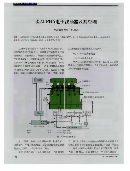
电子气缸注油器pump power unit单元说明书润滑系统主要由泵站,注油单元,注油控制装置-ALCU,负荷变送器,触发系统,辅触发系统,控制面板等组成。
主要部件:泵站单元泵站及启动屏(PUMPSTATIONANDSTARTERPANELS)泵站由2个独立的工作泵,加热盘管,滤器和吸入柜组成。
泵站电源由两路分别供电。
注油器单元每缸配有1个注油器单元,(98-70缸径的发动机注油器单元有2个注油器。
每个注油器单元在进出口侧配有蓄压器(进口侧的蓄压器氮气预充至30-50BAR,出口侧为1.5BAR)。
每个注油器右个注油柱塞,反馈检测元件和电磁阀组成。
注油器控制装置-ALCU(ALPHA LUBRICATORCONTROLUNIT)控制系统主要由三个电子元件组成。
称为ALCU装置MCU(主控单元)BCU(辅控单元)SBU(开关单元)所有电线通过接线终端至主机。
两路电源经USP中的两个相互独立的断路器供给24V直流电。
负荷变送器(LOAD TRANSMITTER)负荷变送器连接在燃油齿条上,因此能连续地把检测到的负荷(百分比)传送给主控单元,主控单元根据此信号和主机转速信号计算主机的负荷。
触发系统(TRIGGERSYSTERM)轴译码器安装在曲轴的前端,信号经接线盒传送至计算机。
由于转角译码器无法安装在主机曲轴的前端,所以一个触发环和转速检测装置安装在飞轮处。
控制面板HMI(HUMANMACHINEINTERFACEPANEL)在控制面板上,可进行单缸注油的调整,显示各种数据报警,手动进行预润滑,并附有泵站的控制按钮。
标准的HMI屏安装在集控室。

这篇7000字的文章,讲透了柴油机ALPHA汽缸注油系统的前世今生......摘要:现代船用大型低速二冲程十字头式柴油机的汽缸润滑一般都是由专门的汽缸油注油装置负责的。
长期以来,船用主机的汽缸油注油系统都为机械式,其主要部件是柱塞式注油泵。
而几十年来的实际使用经验也表明,机械式注油器具有性能可靠,维护量少等许多优点,故在船用主机上占据统治地位。
但机械式注油器也存在着不少的缺点,注油精度低、注油效率差、操作性能差等,已越来越不适应当今的要求。
而随着微电子技术的发展和在船用领域的广泛应用,一种全新的汽缸油注油方式已经出现,那就是MAN B&W公司研制的新型电子注油器――ALPHA LUB RICATOR。
“某某”轮所用主机(HHM-MAN B&W 6S50MC-C)就安装了这一系统。
本文将从其结构、组成、和注油机制等方面着手,结合本人在船的实际经验,对其先进性进行讨论。
一.传统的汽缸油注油系统1.工作原理传统船用主机的汽缸润滑原理是这样的:从汽缸油日用柜来的汽缸油通过输油管送到注油器本体,注油本体在凸轮轴的驱动下以一定的规律泵油,被泵出的油则经过注油管被送到注油嘴,当管内的压力大于汽缸内的压力时,汽缸油便通过注油嘴的止回阀进入到气缸内。
汽缸油注油的最佳时刻是第一道活塞环刚刚通过注油槽的那一刻,此时汽缸油正好注入到两道活塞环之间,然后通过活塞的往复运动,被均匀的分布在汽缸壁上。
图1为传统的机械式汽缸油注油器本体的原理图。
其实质是一组柱塞泵,各缸的注油器连接到同一根轴上,由主机凸轮轴经齿轮驱动,注油器本体内也有一凸轮,用以驱动柱塞,主机运转时此凸轮随主机以一定的速度转动,带动柱塞在套筒内做往复运动。
在输入输出口的止回阀的作用下,汽缸油便以脉冲的形式被不断的泵出。
机械式注油器的注油率可以通过调节柱塞行程,即通过控制柱塞的返回距离来调节。
但改变注油率将导致注油开始时刻发生改变,如减小注油率将导致注油时刻滞后,而增大注油率则会使注油时刻提前。
Alpha Lubricator System707X-40C Alpha Lubricator SystemOperation ManualMC EnginesMAN B&W Diesel A/STeglholmsgade 41DK-2450 Copenhagen SV, DenmarkPhone+45 33 85 11 00Fax+45 33 85 10 30E-mail manbw@manbw.dkAlpha Lubricator System707X-40CTOC 2 (4)Table of ContentsPage List of Abbreviations: 5 1.General Information 6 1.1Main components 6 1.2Working principle 91.3Guidance values automation 102.Operation of the System 10 2.1HMI-Panel / Operating Panel 10 2.2Control buttons and indicator lamps on pump station starter panels 11 2.3Start-up of Alpha Lubricator System (Engine not running) 11 2.4Checks during start-up of the engine 122.5Periodic checks during normal operation of the engine 133.HMI-Panel and Configuration of MCU 13 3.1Description of HMI Panel 13 3.2HMI-Panel operation and configuration of MCU 14 3.2.1Navigation principle 14 3.2.2Reading of total stroke/min [rXXX] 14 3.2.3Reading of total strokes [Str.hi] and [Str.lo] 14 3.2.4Reading of active alarms [ALRXX] 15 3.2.5Reading of logged alarms [LALXX] 15 3.2.6Adjustment of cylinder oil feed rate [F.rAtE] 15 3.2.7Monthly change of operating pumps (master pump) 16 3.2.8Test sequence for inspection during standstill 17 3.2.9Menu structure 17 3.2.10HMI panel parameter reference list 21 3.3MCU setup 32 3.3.1Dip switches for MCU 32 3.3.2Upload of MCU basic program 33 3.3.3Upload MCU set-up file 34 3.3.4MCU LED information 35 3.3.5Read-out of raw parameters in HMI Panel 35Alpha Lubricator System707X-40CTOC 3 (4)Table of ContentsPage 4.Configuration of BCU 36 4.1Injection rate with BCU in control 36 4.2Detection rate (BCU take over from MCU) 36 4.3Number of cylinders for the engine 36 4.4BCU board revision 37 4.5Slow down output 37 4.6Number of lubricators 374.7Upload of BCU basic program 375.Alpha Lubricator – Alarm Handling and Trouble Shooting Guide 38 5.1Fuses 38 5.1.1MCU-Unit 38 5.1.2BCU-Unit 42 5.2External alarm signals 44 5.2.1Common alarm 44 5.2.2MCU power failure 44 5.2.3BCU power failure 45 5.2.4MCU failure 45 5.2.5BCU failure 45 5.2.6Slow-down 45 5.2.7BCU in control 45 5.3MCU – alarm handling and trouble shooting 46 5.3.1Alarms 1-24 – Feedback failure 46 5.3.2Alarm 29 – Marker signal failure from encoder 47 5.3.3Alarm 30 – BCU pickup 1 failure 48 5.3.4Alarm 31 – Trigger signal failure from encoder 49 5.3.5Alarm 33 – Engine stop signal failure 49 5.3.6Alarm 34 – LCD signal abnormal 50 5.3.7Alarm 35 – BCU active signal missing 50 5.3.8Alarm 36 – Astern signal abnormal 50 5.3.9Alarm 37 – Prelubrication signal abnormal 50 5.3.10Alarm 38 – Oil temperature high 50 5.3.11Alarm 39 – Oil pressure low 51 5.3.12Alarm 40 – Speed deviation alarm 51 5.3.13Alarm 41 – Index transmitter abnormal 51Alpha Lubricator System707X-40CTOC 4 (4)Table of ContentsPage 5.3.14Alarm 42 – Cable failure index transmitter 51 5.3.15Alarm 43 – BCU pickup 2 failure 52 5.3.16Alarm 44 – BCU in control 52 5.3.17Alarm 45 and 46 – Thermal overload electric motor 52 5.3.18Alarm 47 – MCU parameter list not loaded 52 5.3.19Alarm 48 – Angle deviation fail 53 5.3.20Alarm 49 – Stand-by pump is running 53 5.4BCU alarms 53 5.4.1Led # 1 BCU internal failure 54 5.4.2Led # 2 Engine stop signal failure 54 5.4.3Led # 3 MCU alive signal missing 54 5.4.4Led # 4 Feedback signal missing on two lubricators 54 5.4.5Led # 5 Feedback signal missing one lubricator 55 5.4.6Led # 6 BCU marker signal 1 and 2 missing 55 5.4.7Led # 7 and 8 BCU marker signal 1 or 2 missing 56 5.5Emergency running without external trigger signals 56 5.6Sequence diagram for alarm handling 58 Appendix 1Function of the LEDs in the Intermediate Box 59 Appendix 2Control Unit Cylinder Lubrication – Logic Diagram 60 Appendix 3Replacement of MCU, BCU, SBU Boards 68 Appendix 4Cylinder oil feed rate during running-in 70 Appendix 5ALCU signal description 72Alpha Lubricator System 707X05-40CList of Abbreviations:This is a list of abbreviations used in this manual.AC Alternating CurrentACC Adaptive Cylinder oil ControlALCU Alpha Lubricator Control UnitAMS Engine alarm SystemBCU Backup Control UnitDC Direct CurrentECR Engine Control RoomFBU Fuse Board UnitFPGA Fast Programmable Graphic ArrayHMI Human Machine InterfaceIC Integrated CircuitLcd Load change dependentLED Light Emitting DiodeMCU Master Control UnitMEP Mean Effective PressurePCB Printed Circuit BoardRPM Revolutions Per MinuteSBU Switch Board UnitTDC Top Dead CentreUPS Uninterruptable Power SupplyIndexCommissioningMaintenanceComponentsElectrical WiringAlpha Lubricator System707X06-40C1.General Information1.1Main componentsThe Alpha Lubricator System Layout is shown in the diagram below:Alpha Lubricator System Layout707-X 01 40C 01BAlpha Lubricator System707X07-40CPump station and starter panelsThe pump station consists of two individually op-erating pumps, heating coil, filters and a suction tank. The power supply to the pump station start-er panels is taken from two separate circuit breakers, one supplying each pump.For further information, see Maker’s pump sta-tion manual.Lubricator unitsThe lubricator units, one for each cylinder, each comprise two lubricators for 98-70 bore engines and one lubricator for medium and small bore engines. Each lubricator unit is equipped with one accumulator with nitrogen pre-pressure of 25-30 bar on the inlet side, and one accumulator on the outlet side of each lubricator, with nitrogen pre-pressure of 1.5 bar.Each lubricator features 3, 4, 5 or 6 lubricating pistons, depending on engine type, a feedback pickup and a solenoid valve.Alpha lubricator control unit – ALCUThe three main electronic components for controlling the lubricating oil are com-prised in one steel cabinet – the so-called ALCU unit.The three units are:MCU(Master Control Unit)BCU (Backup Control Unit)SBU (Switch Board Unit)707X 03 40C 01X Z 707.40A 02One-lubricator unitX Z 707.40A 02X Z 707.40A 03Two-lubricator unitX Z 707.40A 03Alpha Lubricator System707X08-40CA terminal block interfaces all electrical connections to the engine.The 24 V DC power is supplied from two individual power sources, from different breakers in the UPS unit. Please note that some installations might be connected differently by the shipyard.Load transmitterThe load transmitter is connected to the fuel rack, thereby continuously transmitting the fuel index % to the MCU, which calculates the engine load from this information and the detected engine rpm.MCUSBUBCU707-X 01 40C 11X Z 707.40B 05Alpha Lubricator System707X09-40CTrigger system (Shaft encoder)The shaft encoder is connected to the fore end of the crankshaft, and the signals are transmitted to the computer panels via a terminal box. For en-gines on which the crankshaft fore end is not avail-able for angle encoder installation, a trigger ring and tacho pickups are installed at the turning wheel.Backup trigger systemThe backup trigger system comprises two tacho pickups in a box at the turning wheel, thereby transmitting the engine rpm to the BCU. The backup pickups are also connected to the MCU for surveillance purposes.Human Machine Interface (HMI) panelOn the HMI panel, individual cylinder lubrication adjustment is possible, various values and alarms are displayed, control buttons for thepump station are available, and manual execution of prelubrication is possible. As standard the HMI-panel is mounted in the engine control room.1.2Working principle·The pump station supplies the Alpha Lubricators with 40-50 bar oil pressure.·The MCU controls the oil injection by activating a solenoid valve situated on the relevant lubricator.X Z 707.40A 05X Z 707.40A 05X Z 707.40B 07S 903-21 06ALAMPTEST PUMP 1PUMP 2PRELUB.ESC ENTERCommon alarmFeedback failure Mark/trig failure Index failure Oil pressure low Min.MCU Auto BCUEngine speedIndexLubrication Deg.rpm %bar°C 120120BCU in Ctrl.· A feedback signal from each lubricator indicates that oil injection has taken place. This is shown by Light Emitting Diodes (LEDs) on intermediate boxes foreach cylinder.·Timing is based on two signals from the angle encoder, a TDC cyl. 1 marker and a crankshaft position trigger. The Alpha Lubricator system is normally timedto inject cyl. oil into the piston ring pack during the compression stroke.·The cylinder lubrication is based on a constant amount of oil being supplied per injection. The specific feed rate is controlled by variation of the injection fre-quency.·The injection frequency is calculated from index and speed, and is normally pro-portional to the engine MEP. However, a power Mode or RPM Mode is possible.·The basic cylinder oil feed rate at MCR (100%) is calculated as a correlation be-tween a number of injections / rpm and the stroke of the lubricators.·On the HMI panel, adjustment of lubrication feed rate for individual cylinders is possible between 60% and 200%. Default value is 100%.·During normal operation the system is controlled by the MCU. If any failures are detected in the system, a common alarm is activated in the control room. Thedetailed alarm reference is displayed on the HMI panel.·If a critical failure in the MCU is detected, the BCU automatically takes over (Note – control switch must be in “auto” position). An indication lamp “BCU incontrol” is lit on the panel that contains the HMI panel.Note that on older installations, the indication lamps can be situated elsewhere.·The BCU is based on random timing and RPM Mode. The injection frequency is adjustable on the BCU and is normally, as minimum, set to the basic cylinderoil feed rate for the engine, plus 50%.1.3Guidance values automationCylinder Lub. Oil Pressure Cylinder Lub. Oil TemperatureNormal Service Value40 – 50 bar Normal Service Value30 – 60° CAlarm min.35 bar Alarm max.70° CAlarm max.60 bar2.Operation of the System2.1HMI-Panel / Operating Panel1.As standard, the HMI panel (for description, see Section 3), a three-positionmode switch, and an indicator lamp are mounted in the engine control room.However, an additional HMI panel, etc. can, as an option, be installed in oneof the pump station starter panels. In this case a local/remote switch has to beinstalled.The three-position mode switch enables selection between·Auto-mode– BCU takes over automatically, if lubrication cannot be main-tained by the MCU. If the BCU has taken over the control, this mode canonly be cleared by manually switching to MCU-mode, and back to Auto-position.·MCU-mode – Forced MCU control.·BCU-mode– Forced BCU is in control.2.An orange Indicator lamp – Indicates that BCU is in control.2.2Control buttons and indicator lamps on pump station starter panelsEach starter panel contains the following switches, buttons and lamps:1. A three-position switch controls the pump activity as follows:·REM.(Remote)– Automatic control of pumps (normal working position)·LOC.(Local)– Manual start of the pump·OFF – Manual stop of pump.2. A two-position main switch – Switches off 3 x 440 V AC power supply.3. A green indicator lamp – lights if pump is running.4. A white indicator lamp – lights if 3 x 440 V AC from fuse panels is switchedON.2.3Start-up of Alpha Lubricator System (Engine not running)1.To fill the pump station with cylinder oil, open the valves for the cylinder oilsupply line and the venting cock (if installed). Close the venting cock when cyl-inder oil flows out into the venting line.2.Switch on the main switches on the pump station starter panels.3.Switch to “Local” and manually start pump 1 and subsequently pump 2.Check that both pumps can run simultaneously.4.Check that the pressure differential indicator on the pump station filter isgreen, when one pump is operating.5.Check that the oil pressure builds up to 40-50 bar, or carry out adjustment on the pressure control valve on top of the pump station.Check that the pressure remains at an acceptable level, also with two pumps running.6.Press [ESC ] and [PRELUB ] at the same time on the HMI panel to activate the test sequence, and check that all lubri-cators are operating correctly by watch-ing the LEDs (feedback signals) on the intermediate boxes for each lubricator.Stop the test sequence by pressing [PRELUB ] again.At commissioning or after overhaul of the system, check visually from the scavenge air receiver that all non-return valves inject cylinder oil into the cylinder liners.7.Stop the pumps manually, and switch to “Remote ” on the starter panels. The Alpha Lubricator System is now ready for normal operation.8.For engineers commissioning the Alpha Lubrication System, procedures are made for Testbed Commissioning and Dock Trial Commissioning. The proce-dures are shown in the Commissioning chapter. For flushing the system, please read special instruction.2.4Checks during start-up of the engine1.Upon start of the engine's auxiliary blowers, the Alpha Lubricator System is programmed to carry out automatic prelubrication. The pump station will au-tomatically stop if the engine is not started shortly after.2.Check that a pump on the pump station automatically starts up when the en-gine is started, and that the cyl. oil pressure builds up to 40-50 bar.3.Check that all the green LEDs flash on the intermediate boxes for each lubri-cator.4.Check that no alarm is detected in the control room and on the HMI panel.X Z 707.40A 08N A 903-2.1 225 022.5Periodic checks during normal operation of the engine1.Check that all lubricating points supply oil by:a)inspecting that all LEDs for feedback indication on the intermediate boxes are flashingb)feeling the pressure shocks from injection of the lubricators on each lubricator pipe. If in doubt, dismantle the pipe at the cylinder liner to observe the oil flow.2.Inspect the local oil pressure gauge on the pump station.Normal service value = 40 – 50 bar.3.Check for oil leakages in the system.3.HMI-Panel and Configuration of MCU3.1Description of HMI PanelBar graphsThe two upper bar graphs display relative values in percent of engine speed and fuel index ( mep%), respectively. The range is from 0 to 120 percent, where 100 percent corresponds to the physical val-ues at MCR. The third upper bar graph displays oil pressure in the range of 0 to 100 bar.Fault category indicatorsFive LEDs for indication of fault category are placed below the numerical display, as follows:·Oil pressure low ·Fuel index failure ·Marker/Trigger failure ·Feedback failure·Common alarm –For explanation of the alarm code, see the alarm list in Section 5.Buttons [ ]Move up in the HMI panel menu structure. See item 3.2.9.[ ]Move down in the HMI panel menu structure. See item 3.2.9.[ESC ]Move to the left in the HMI panel menu structure. See item 3.2.9.LAMPTEST PUMP 1PUMP 2PRELUB.ESCENTER Common alarmFeedback failure Mark/trig failure Index failure Oil pressure low Min.Engine speedIndexOil pressure Deg.rpm %bar°C 120120100 bar[ENTER ]Move to the right in the HMI panel menu structure. See item 3.2.9.[LAMPTEST ] All lamps are lit in the HMI panel.[PUMP 1]Starts or stops booster pump 1.[PUMP 2]Starts or stops booster pump 2.[PRELUB ]Can only be activated when engine is stopped. Activates prelu-brication sequence.The lubricators will be activated continuously from Lubricator 1A, 1B, 2A,... 14B. The cycles will be repeated a pre-pro-grammed number of times (normally 12).[ESC ] + [PRELUB ]Starts test sequence of 1000 pre lubrications. The test se-quence is stopped by pressing [PRELUB ] again.[ESC ] + [PUMP 1]Selects default booster pump to be pump 1.[ESC ] + [PUMP 2]Selects default booster pump to be pump 2.3.2HMI-Panel operation and configuration of MCUThis section describes the menu system in the HMI-panel numerical display. Six of the most common manoeuvres are described below and the complete structure and parameters are shown in items 3.2.9 and 3.2.10.3.2.1Navigation principleHMI panel menu system is a hierarchic menu system. The following four buttons are used to navigate through the menu system.[ ]Move up in the HMI panel menu structure. See item 3.2.9.[ ]Move down in the HMI panel menu structure. See item 3.2.9.[ESC ]Move to the left in the HMI panel menu structure. See item 3.2.9.[ENTER ]Move to the right in the HMI panel menu structure. See item 3.2.9.3.2.2Reading of total stroke/min [rXXX]Press [ ] or [ ] until rXXX is shown in the display(Note that this value is an average value over 1 min.).3.2.3Reading of total strokes [Str.hi] and [Str.lo]1.Press [ ] or [ ] until diSP is shown in the display.2.Press [ENTER ] and [ ] or [ ] until Str.hi or Str.lo is shown in the dis-play.3.Press [ENTER ] to read the stroke counter.diSPStr. hi Str. loxxxxx4.Press [ESC ] to return to main menu (one press [ESC ] = one step backwards).5.The total number of strokes is a ten digit number and is obtained by combining the values of Str.hi and Str.lo as follows:The value of Str.lo represents the five rightmost figures and the value of Str.hi the five leftmost figures.Example:The total stroke amount is used to calculate the amount of cylinder lube oil used within a specified amount of time. The following formula can be used:See example on page 31 (str.hi).3.2.4Reading of active alarms [ALRXX]Press [ ] or [ ] until ALRXX is shown in the display.For explanation of the alarm code see the alarm list in Section 5.3.2.5Reading of logged alarms [LALXX]1.Press [ ] or [ ] until LALxx is shown in the display.For explanation of the alarm code see the alarm list in Section 5.2.To clear a logged alarm, press [ENTER ] when the alarm is shown in the display. To clear all logged alarms, press [ENTER ] for 5 seconds while an LALxx is shown in the display.3.2.6Adjustment of cylinder oil feed rate [F .rAtE]The feed rate is entered in the HMI panel as a percent value.–For systems with MEP regulation, 100% feed rate setting normally corresponds to the basic setting with reference to service letters and general guidelines for cylinder lubri-cation.Str. hi1 2 3 4 5Str. lo6 7 8 9 0Total number of strokes == 1 2 3 4 5 6 7 8 9 0707-X 10 40C 3235ALRXX707-10 40C 323F .rAtECyl.xx Cyl.1SEt.Alxxxxx707-10 40C 324–For systems with Alpha ACC (Adaptive Cylinder oil Control) the feed rate is set proportionally to the sulphur content in the fuel oil. The feed rate setting per-centage can be obtained from the regulation plate.1.Press [ ] or [ ] until F.rAtE is shown on the display.2.Press [ENTER ] and [CYL 1] is shown on the display.3.Press [ ] or [ ] until the cylinder to be adjusted is shown or select SEt.Al to set all the cylinders to the same value.4.Press [ENTER ] and the current feed rate is shown. Please note that if SEt.Al was selected the value shown is the last value saved in SEt.Al, and this value is not true if any cylinder has been individually adjusted since.5.Press [ ] or [ ] – The oil feed rate can be changed to the desired value be-tween 60 and 200%.6.Press [ENTER ] – The value is stored in the computer memory, and the main display will prompt with “Save ”.7.Press [ESC ] three times to return to main menu.3.2.7Monthly change of operating pumps (master pump)1.Check which pump is running (1 or 2)2.Press [ESC ] + [PUMP 1] or [PUMP 2] (pump not running).3.New master pump is now chosen and running.Alpha Lubricator SystemAdaptive Cylinder oil Control707-X 01 40C 12Sulphur Specific dosage HMI setting%g/BHPh g/kWh3.2.8T est sequence for inspection during standstill1.Press [ESC] + [PRELUB] simultaneously(the lubricators will lubricate 1000 times).2.Press [PRELUB] the test sequence will stop.3.2.9Menu structureThe following pages show how to navigate in the HMI-panel menu structure.Alpha Lubricator HMI Panel menu structure – part 1Alpha Lubricator HMI Panel – menu structure – part 2, setup menu3.2.10HMI panel parameter reference listA.inJ [°](abbr. of angle injection)The specific crank angles for oil injection for each lubricator. Normally it is thecrank angle at the point where No. 1 piston ring passes the oil quills on the upwardstroke of the piston.The number consists of an online measurement of the angle for the first flank ofthe feedback signal plus the angle corresponding to the hydraulic delay time.Only active when engine is running ahead.Normal value for cylinder one is around 270 to 310°.AbS.Lo [%] (abbr. of absolute low)Absolute minimum reduction percentage. The injection frequency can be reducedto the value of AbS.Lo in % of the basic frequency. The basic frequency is thefrequency at 100 % load, 100 % rpm, 100 % feed rate setting and is defined as1/rE.injALR XX (abbr. of alarm XX)Code number for active alarms, where the number ‘XX’ represents the alarm code.For explanation of the alarm code see the alarm list in Section 5.Ang.dE(abbr. of angle deviation)The Maximum allowable angle difference between the marker signal (TDC signal)from the encoder (or trigger ring) and the marker signal from the BCU pickups.Only valid when engine is running ahead.Normal value is 2 degrees.Co.ALr (abbr. of common alarm)Manual activation of the MCU common alarm output.ALCU/x1:1, ALCU x1:2 (MCU/J32:1, MCJ/J32:2), dry contact, normally closed.Connt(abbr. of connection test)Connection test menu. Blocked when the engine is running.Cr.Ang [°] (abbr. of crank angle)Indication of actual crank angle from the shaft encoder. Blocked when the engine is running. Only valid when continuously turned in same direction by turning gear and after having passed TDC cyl. 1. The indication is sensitive to rocking motion and should therefore only be used as an indication.diSP (abbr. of display)Display menu. Values and parameters are displayed, but cannot be changed from diSP menu.F.hi [%] (abbr. of feed rate high)Feed rate setting high limit. The maximum possible feed rate setting on the HMI panel. The value is a percentage of the basic recommended feed rate setting. Normal value is 200 %.F.Lo [%](abbr. of feed rate low)Feed rate setting low limit. The minimum possible feed rate setting on the HMI panel. The value is a percentage of the basic recommended feed rate setting. Normal value is 60 %.F.rAtE(abbr. of feed rate)Feed rate setting adjustment. The feed rate can be adjusted individually for each cylinder or for all cylinders at one time with the SEt.Al function. Please note that the value shown when entering the SEt.Al menu is the last value saved in the SEt.Al menu. Thus if the cylinders have been adjusted individually since, the value shown when entering the SEt.Al function is no longer true for all cylinders.100 % feed rate setting normally corresponds to basic setting. (Reference is made to the guidelines for cylinder lubrication)F.SCuF [%] (option) (abbr. of feed rate scuffing)Feed rate increase in case of scuffing. Input for each cylinder on the MCU board can receive signal from a cylinder liner temperature monitoring system. If begin-ning scuffing is detected, a signal can be given and extra lubrication activated. Please contact MAN B&W if this function is needed.Normal value is 200 %FE.AD(abbr. of feed rate adjustment)Feed rate regulation parameter adjustment menu.FPgA(abbr. of fast programmable graphic array)FPGA software revision number. The IC (Integrated Circuit) (u33) contains the program for the FPGA. If the FPGA code is updated, a new IC will have to be in-stalled. The current FPGA software revision is 6.gEn(abbr. of generator)Load transmitter calibration menu for generator curve running. When the engine is running 50 % load and 100 % load (with reference to testbed results), enter the menu by pressing [ENTER] and choose the correct engine load (50 % or 100 %) followed by pressing [ENTER]. The program will respond with donE.hY.dEL [ms](abbr. of hydraulic delay)Hydraulic delay (time offset value). The value is inserted to compensate for the time-delay from the first flank of the feedback signal, until the oil enters the cylinder through the cylinder liner non-return valves. The longer the hydraulic delay - the earlier the solenoid valve is activated. The Hydraulic delay is calculated in the de-sign process and is confirmed by measurements on prototype engines. A good es-timate of the value is 1 ms for each meter pipe length from the lubricator to the cylinder liner. The value cannot be adjusted individually for each cylinder, but is common for all cylinders.Normally values are from 1 to 6 ms.in.A [mA] (abbr. of index ampere)Read out of the index transmitter current. The mA signal from the index transmitter without scaling. Used for mechanical adjustment of the index transmitter during commissioning. The index transmitter is adjusted to 4.5 mA at mechanical mini-mum index and to 19.5 mA at mechanical maximum index. The adjustment is made on testbed before initial start up.in.AdJ(abbr. of index adjustment)Index transmitter adjustment/calibration menu. The adjustment is done during run-ning at testbed, at 50 % load and at 100 % load. Choose between propeller curve (ProP) or generator curve (gEn). Select the load percentage (50 % or 100 %) cor-responding to the actual load. Press [ENTER] and the system replies donE. After-wards press [ESC] 4 times until you are back in the main menu showing RPM. The system has now been calibrated. Use the vALue menu if manual correction of the parameters is necessary.in.hi [%] (abbr. of index high)Index transmitter raw calibration value. The index transmitter calibration values are given as an index low (in.Lo) value and an index high (in.hi) value. These val-ues are the theoretical index percentages when the pickup gives respectively 4 and 20mA. Estimated values are pre-programmed from MAN B&W, and the sys-tem is calibrated by means of the (ProP) or (gEn) menus on testbed. The raw val-ues should only be changed if the automatic calibration in the ProP and gEn menus, proves insufficient.The values are normally around –30 to –10 for [in.Lo] and around 125 to 140 for [in.hi].in.Lo [%](abbr. of index low)See in.hi.inJ.AL(abbr. of injection algorithm)Injection amount algorithm menu. Injection rate calculation can be chosen in pro-portion to mean efficient pressure (nneP), rpm (rPnn) or power (Po.).Normal mode is nnep proportional.inJ.oF [°] (abbr. of injection offset)Injection offset. Angle offset inserted to compensate for small deviations between the injection angle determined in the design process and the actual crank angle for injection. The actual crank angle for injection is normally when the first piston ring passes the oil quill during the upward stroke of the piston. inJ.oF can be ad-justed within +/– 5 °.The value cannot be adjusted individually for each cylinder, but is common for all cylinders.Normal value is 0.LALXX (abbr. of logged alarm XX)Logged alarms where the number ‘XX’ represents the alarm code. When an alarm is activated, it will appear as both ALRXX and LALXX. The LALXX will remain after the alarm is gone. For explanation of the alarm code see the alarm list in Sec-tion 5.To clear a logged alarm press [ENTER] while the alarm code is displayed. To clear all logged alarms press [ENTER] for 5 seconds while one of the alarm codes is dis-played.Lcd X(abbr. of load change dependent X)Load change dependent extra lubrication status. X indicates the status. When LCD is active, i.e. when a load change situation occurs, the status changes from 0 (=off) to 1 (=on). The normal hold time is 30 min.Lcd(abbr. of load change dependent)Load change dependent extra lubrication parameter adjustment menu. Six param-eters, P1 to P6, can be adjusted. For further explanation see P1 to P6.MEP[%](abbr. of mean efficient pressure)Mean effective pressure percentage (equal to torque percentage and index per-centage). Scaled read out of the index transmitter input. The value is used for the amount regulation. When generator curve running the value is equal to the load percentage. When ideal propeller curve running normal values are: 25 % load =。