TAPTITEII三角自攻螺丝标准
- 格式:docx
- 大小:3.84 MB
- 文档页数:28

三角牙螺纹标准一、螺纹规格和尺寸三角牙螺纹的规格和尺寸应符合相关国家标准和行业标准。
通常包括公制和英制两种标准,其中公制标准以M表示,如M20、M30等,英制标准则以英寸表示,如1/4英寸、3/4英寸等。
三角牙螺纹的基本尺寸包括外径、内径、螺距等。
二、螺纹公差和配合三角牙螺纹的公差和配合应符合相关标准,根据不同的使用场合和要求,分为不同的等级。
一般而言,三角牙螺纹的精度要求较高,对于需要紧密配合的场合,应选用较低的公差等级,以保证螺纹的配合精度。
三、螺纹外观和形状三角牙螺纹的外观和形状应符合以下要求:1.螺纹牙顶应圆整,牙底应平滑,无锐角或倒角;2.螺纹断面应具有一定的厚度,以保证螺纹的强度;3.螺纹长度应满足使用要求,过长或过短都不利于使用;4.同轴度误差应控制在一定范围内,以保证螺纹的配合精度。
四、螺纹使用性能三角牙螺纹的使用性能应满足以下要求:1.承载能力:三角牙螺纹的承载能力应满足使用要求,包括拉伸、压缩、弯曲等载荷;2.耐磨性:三角牙螺纹的耐磨性应满足使用要求,以保证长时间使用的稳定性;3.耐腐蚀性:三角牙螺纹的耐腐蚀性应满足使用要求,对于腐蚀性介质和环境,应选用相应的材料和表面处理工艺;4.抗疲劳性:三角牙螺纹的抗疲劳性应满足使用要求,以保证在交变载荷作用下不发生疲劳断裂。
五、螺纹试验方法三角牙螺纹的试验方法应符合相关标准,一般包括外观检测、尺寸检测、性能检测等。
外观检测主要检查螺纹的完整性和表面质量;尺寸检测主要测量螺纹的外径、内径、螺距等尺寸;性能检测主要测试螺纹的承载能力、耐磨性、耐腐蚀性等性能。
六、螺纹标记方法三角牙螺纹的标记方法应符合相关标准,一般包括以下内容:1.规格和尺寸:标注螺纹的规格和尺寸;2.材质和材料:标注螺纹所用的材质和材料;3.加工方法:标注螺纹的加工方法,如车削、铣削等;4.其他要求:根据具体要求,标注其他相关信息,如表面处理等。
七、螺纹加工和检验三角牙螺纹的加工和检验应符合相关标准,一般包括以下要求:1.加工设备:选用合适的加工设备,如车床、铣床等;2.刀具选择:根据不同的材质和加工要求,选择合适的刀具;3.加工参数:合理设置加工参数,如转速、进给速度等;4.检验方法:采用合适的检验方法,如千分尺测量、显微镜观察等。

自攻螺丝扭力标准
自攻螺丝是一种常见的螺纹连接件,广泛应用于家具、机械设备、汽车等领域。
在使用自攻螺丝时,扭力是一个非常重要的参数,它直接影响着螺丝的安装质量和使用寿命。
因此,制定和遵守自攻螺丝扭力标准是非常重要的。
首先,我们需要了解什么是自攻螺丝扭力标准。
自攻螺丝扭力标准是指在安装
自攻螺丝时所需的扭力范围。
这个扭力范围是根据螺丝的直径、材质和螺纹类型等因素来确定的,其目的是确保螺丝在安装时能够达到合适的紧固力,既不会过紧导致损坏,也不会过松导致松动。
其次,自攻螺丝扭力标准的制定是基于对螺丝材料和使用环境的深入研究和实
验数据的分析得出的。
不同材质和直径的自攻螺丝在不同的使用环境下需要的扭力是不同的,因此制定统一的标准对于确保螺丝的安装质量至关重要。
此外,遵守自攻螺丝扭力标准对于产品质量的稳定性和可靠性也具有重要意义。
如果在安装过程中未能严格按照扭力标准进行操作,就有可能导致螺丝的过紧或过松,从而影响产品的使用寿命和安全性。
因此,制造商和使用者都应该严格遵守自攻螺丝扭力标准,确保螺丝的安装质
量和产品的可靠性。
制造商应该在生产过程中严格控制螺丝的质量,并提供相应的安装说明和扭力标准;而使用者则应该在安装过程中严格按照说明书和标准操作,以确保产品的安全可靠。
总之,自攻螺丝扭力标准是保证螺丝安装质量和产品可靠性的重要保障。
只有
严格遵守扭力标准,才能确保螺丝在安装过程中达到合适的紧固力,从而保证产品的安全可靠性。
希望所有相关制造商和使用者都能重视自攻螺丝扭力标准,共同为产品质量和用户安全保驾护航。

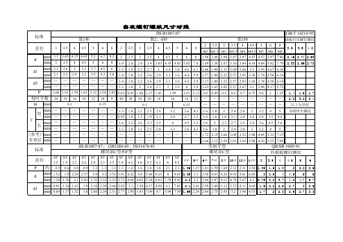
自攻螺丝规格表(可以直接使用,可编辑实用优秀文档,欢迎下载)自攻螺丝規格表-JISJIS公称尺寸T1.2 T1.4 T1.6 T1.7 T2.0 T2.3 T2.5 T2.6 T3.0 T3.5 T4.0 T4.5 T5.0螺纹尾形AB AB AB AB AB AB ABAABAABAABAABAABAAB B B B B B.BT B.BT B.BT B B B B B BBT BT BT BT BT BT每寸扣数T.P.I 64 56 48 48 40 32 28 28 24 18 20 16 18 14 16 12 16 外最大(mm) 1.2 1.4 1.6 1.7 2 2.3 2.5 2.7 2.6 3.1 3 3.65 3.5 4.15 4 4.65 4.5 5.2 5径最小(mm) 1.15 1.35 1.52 1.62 1.9 2.2 2.4 2.6 2.5 3 2.9 3.5 3.4 4 3.85 4.5 4.35 5 4.85内径最大(mm) 1 1.1 1.3 1.4 1.5 1.7 1.9 1.9 2 2.2 2.3 2.6 2.7 3 3.3 3.4 3.7 3.8 最小(mm) 0.95 1.05 1.2 1.3 1.4 1.6 1.8 1.8 1.9 2.1 2.2 2.5 2.6 2.9 3.2 3.3 3.5 3.6长度> 2.5 2.5 2.5 2.5 3 4 4 4 4 6 8 8 10(mm) < 6 6 8 8 15 18 20 25 40 50 50 50 50自攻螺丝规格表-ANSI公称尺寸#2 #3 #4 #5 #6 #7 #8 #10 #12螺纹尾形AB ABAABAABAABAABAABAABAAB B.BT B.BT B.BT B.BT B.BT B.BT B.BT B.BT B.BT每寸扣数T.I.P 32 23 24 20 18 20 16 19 15 18 12 16 11 14 外最大(mm) 2.24 2.57 2.9 3.3 3.58 3.53 4.01 3.91 4.27 4.22 4.93 4.8 5.61 5.46 径最小(mm) 2.13 2.46 2.79 3.2 3.46 3.43 3.86 3.79 4.12 4.09 4.78 4.65 5.64 5.31 内最大(mm) 1.63 1.91 2.11 2.18 2.41 2.39 2.59 2.64 2.9 3.92 3.12 3.1 3.38 3.58 4.11 4.17 径最小(mm) 1.52 1.8 1.98 2.08 2.29 2.44 2.52 2.74 2.77 3.2 3.43 3.94 3.99 长度> 1/8 3/16 3/16 1/4 1/4 5/16 5/16 5/16 5/16 3/8 (mm) < 5/8 3/84 1.25 1.5 2 2 2 2 2 2螺丝基础知识螺丝知识 2021-05-03 08:44阅读412 评论1字号:大中小当今世界上长度计量单位主要有两种,一种为公制,计量单位为米(m)、厘米(cm)、毫米(mm)等,在欧州、我国及日本等东南亚地区使用较多,另一种为英制,计量单位主要为英寸(inch),相当于我国旧制的市寸,在美国、英国等欧美国家使用较多。


自攻螺丝規格表-JISJIS公称尺寸T1.2 T1.4 T1.6 T1.7 T2.0 T2.3 T2.5 T2.6 T3.0 T3.5 T4.0 T4.5 T5.0螺纹尾形AB AB AB AB AB AB ABAABAABAABAABAABAAB B B B B B.BT B.BT B.BT B B B B B BBT BT BT BT BT BT每寸扣数T.P.I 64 56 48 48 40 32 28 28 24 18 20 16 18 14 16 12 16 外径最大(mm) 1.2 1.4 1.6 1.7 2 2.3 2.5 2.7 2.6 3.1 3 3.65 3.5 4.15 4 4.65 4.5 5.2 5 最小(mm) 1.15 1.35 1.52 1.62 1.9 2.2 2.4 2.6 2.5 3 2.9 3.5 3.4 4 3.85 4.5 4.35 5 4.85 内径最大(mm) 1 1.1 1.3 1.4 1.5 1.7 1.9 1.9 2 2.2 2.3 2.6 2.7 3 3.3 3.4 3.7 3.8 最小(mm) 0.95 1.05 1.2 1.3 1.4 1.6 1.8 1.8 1.9 2.1 2.2 2.5 2.6 2.9 3.2 3.3 3.5 3.6 长度(mm)> 2.5 2.5 2.5 2.5 3 4 4 4 4 6 8 8 10< 6 6 8 8 15 18 20 25 40 50 50 50 50 自攻螺丝规格表-ANSIANSI B18.6.3公称尺寸#2 #3 #4 #5 #6 #7 #8 #10 #12螺纹尾形AB ABAABAABAABAABAABAABAAB B.BT B.BT B.BT B.BT B.BT B.BT B.BT B.BT B.BT每寸扣数T.I.P 32 23 24 20 18 20 16 19 15 18 12 16 11 14 外径最大(mm) 2.24 2.57 2.9 3.3 3.58 3.53 4.01 3.91 4.27 4.22 4.93 4.8 5.61 5.46最小(mm) 2.13 2.46 2.79 3.2 3.46 3.43 3.86 3.79 4.12 4.09 4.78 4.65 5.64 5.31 内径最大(mm) 1.63 1.91 2.11 2.18 2.41 2.39 2.59 2.64 2.9 3.92 3.12 3.1 3.38 3.58 4.11 4.17最小(mm) 1.52 1.8 1.98 2.08 2.29 2.44 2.52 2.74 2.77 3.2 3.43 3.94 3.99 长度(mm)> 1/8 3/16 3/16 1/4 1/4 5/16 5/16 5/16 3/8< 5/8 3/84 1.25 1.5 2 2 2 2 2螺丝基础知识螺丝知识 2当今世界上长度计量单位主要有两种,一种为公制,计量单位为米(m)、厘米(cm)、毫米(mm)等,在欧州、我国及日本等东南亚地区使用较多,另一种为英制,计量单位主要为英寸(inch),相当于我国旧制的市寸,在美国、英国等欧美国家使用较多。

自攻螺纹标准
自攻螺纹标准是指自攻螺钉制品的相关标准规范。
自攻螺钉是一种针对薄壁材料的紧固件,常用于金属、木材和塑料等材料的连接。
自攻螺钉标准主要包括以下几个方面:
1. 尺寸标准:包括螺纹直径、螺纹长度、头部直径等。
2. 材料标准:包括自攻螺钉的材质、表面处理、性能等。
3. 使用标准:包括自攻螺钉的使用环境、使用要求等。
4. 检验标准:包括自攻螺钉的检验方法、检验标准等。
目前,国际上常用的自攻螺纹标准包括ISO、DIN、ANSI、JIS等。
在应用中,需要根据具体的使用需求,选择符合自身要求的标准型号和产品。


自攻螺丝iso标准
自攻螺丝的ISO标准主要包括ISO 898-1和ISO 898-2。
这些标准规定了自攻螺丝的材料、机械性能、表面处理、尺寸和公差等方面的要求。
此外,ISO 10664标准也规定了自
攻螺丝在紧固过程中的扭矩要求。
这些标准是确保自攻螺丝质量和性能的重要依据,也是工业界广泛接受和使用的规范。
自攻螺钉的材料可分为碳钢和不锈钢两种,其中碳钢材料以1022中碳钢为主。
自攻螺钉的头部一般为尖头或圆头,并带有通孔,以便于安装。
自攻螺钉具有较高的硬度和较小的横截面,能够在被连接材料中自行攻钻出相应的螺纹,然后拧入并固定连接。
在金属或非金属材料的预钻孔中,自攻螺钉可以自行攻钻出所配合的阴螺纹,适用于薄板或轻金属材料的连接。
自攻螺钉的种类有很多,以下是一些常见的分类方式:根据自攻螺钉的螺纹类型,可以分为普通自攻螺钉、自切自攻螺钉、自钻自攻螺钉等。
根据自攻螺钉的头部形状,可以分为平头自攻螺钉、圆
头自攻螺钉、半圆头自攻螺钉、六角头自攻螺钉等。
根据自攻螺钉的材质,可以分为不锈钢自攻螺钉、碳钢自攻螺钉、铜自攻螺钉等。
根据自攻螺钉的长度,可以分为10mm自攻螺钉、20mm 自攻螺钉等。
此外,根据不同的使用工况,自攻螺钉还有很多其他的种类,如十字槽盘头自切自攻螺钉、十字槽沉头自切自攻螺钉、十字槽半沉头自切自攻螺钉、六角头自切自攻螺钉等。
以上信息仅供参考,如需了解更多信息,建议查阅相关书籍或咨询专业人士。
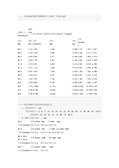
<一>﹑公制机械牙粗牙规格螺丝尺寸标准(牙型角:60˚)标称尺寸 Designation螺距Pith外径Dia.of Circle有效直径Dia.of Triangle最大 Max 最小 Min 公差 Tolerance 最大 Max 最小 Min公差 Toleranc eM2.0 0.40 1.981 1.886 0.095 1.721 1.654 0.067 M2.5 0.45 2.480 2.380 0.100 2.188 2.117 0.071 M3.0 0.50 2.980 2.874 0.106 2.655 2.580 0.075 M3.5 0.60 3.479 3.354 0.125 3.089 3.004 0.085 M4.0 0.70 3.978 3.838 0.140 3.523 3.433 0.090 M4.5 0.75 4.478 4.338 0.140 3.991 3.901 0.090 M5.0 0.80 4.976 4.826 0.150 4.456 4.361 0.095 M6.0 1.00 5.974 5.794 0.180 5.324 5.212 0.112 M8.0 1.25 7.972 7.760 0.212 7.160 7.042 0.118 M10 1.50 9.968 9.732 0.236 8.994 8.862 0.132 M12 1.75 11.966 11.701 0.265 10.829 10.679 0.150 M14 2.00 13.962 13.682 0.280 12.663 12.503 0.160 M162.00 15.96215.6820.280 14.66314.503 0.160<三>三角自攻螺丝长度系列及标准公差 1﹑长度系列尺寸(mm )优先系列:4﹑5﹑6﹑8﹑10﹑12﹑15﹑18﹑22﹑25﹑30﹑36﹑42﹑50﹑60﹑80﹑100等 允选系列:20﹑28﹑32﹑40﹑45﹑55﹑70﹑90等 2﹑螺丝长度公差表 ( mm)M2.0长度Length <2mm2〜3mm >3mm公差Tolerance +0〜-0.15 +0〜-0.2 +0〜-0.3M2.5长度Length <4mm4〜10mm 10〜20mm >20mm公差Tolerance +0〜-0.3 +0〜-0.4 +0〜-0.6 +0〜-0.8M3.0﹑M3.5 M4.0﹑M4.5长度Length <20mm20〜40mm >40mm公差Tolerance +0〜-0.6 +0〜-0.8 +0〜-1.0M5以上长度Length <10mm>10mm公差Tolerance +0〜-0.8 +0〜-1.0四﹑公制机械牙粗牙规格螺丝主要机械性能参数标准(5.8级以上)标称尺寸Designation 螺距 Pith 破坏扭力 抗张力表面渗碳热处理规格 >N. m >Kg 表面硬度 心部硬度 硬化层深度 M2.0 0.40 0.4 120 460-600 250-380 0.04-0.10 M2.5 0.45 0.6 180 460-600 250-380 0.04-0.10 M3.0 0.50 0.9 270 460-600 250-380 0.04-0.10 M3.5 0.60 1.5 360 460-600 250-380 0.05-0.18 M4.0 0.70 2.5 480 560-650 250-380 0.05-0.18 M4.5 0.75 3.5 600 560-650 250-400 0.1-0.25 M5.0 0.80 5 750 560-650 250-400 0.1-0.25 M6.0 1.00 8.5 1100 560-650 250-400 0.15-0.30 M8.0 1.25 20 2000 560-650 250-400 0.15-0.30 M10 1.50 40 3100 560-650 250-400 0.15-0.30 M12 1.75 65 4400 560-650 250-400 0.15-0.30 M14 2.00 100 6000 560-650 250-400 0.15-0.32 M162.00 1608200560-650250-400 0.15-0.32五﹑公制机械牙粗牙规格螺丝头型及槽形选择 <一>﹑公制机械牙粗牙规格螺丝头型种类1﹑盘头 P 2﹑伞头 T 3﹑平顶沉头 F4﹑六角头 H 5﹑内六角圆柱头 6﹑扁头B 或圆头R <二>﹑公制机械牙粗牙规格螺丝头型选择1﹑优先选用盘头P :有用到扁头B 及圆头R 时需考虑用盘头替代,被锁付零件孔相对较小﹑材质较硬时均可考虑用盘头螺钉。

自攻螺丝规格尺寸表第一篇:自攻螺丝规格尺寸表介绍自攻螺丝是一种常见的机械连接件,主要用于连接薄板。
它具有自钻孔、自攻丝的功能,不需要钻孔或打螺母,能够节省安装时间和成本。
自攻螺丝有许多不同的规格尺寸,不同的规格适用于不同的连接需求。
本篇文章将介绍自攻螺丝的规格尺寸表及其用途。
自攻螺丝的规格尺寸通常由直径、长度、螺纹类型和头部类型组成。
直径通常在0.8mm到6.3mm之间,长度在2mm到150mm之间,头部类型包括扁平头、圆头、半圆头和锥形头等。
在不同的应用场景中,选择合适的规格尺寸非常重要,能够确保连接的牢固稳定。
自攻螺丝的螺纹类型分为两种:A型和AB型。
A型自攻螺丝适用于连接薄薄的材料,如金属板材、塑料、木料等。
AB 型自攻螺丝适用于连接较厚的材料,如钢板、铝板等。
在选择螺纹类型时,需要根据连接的材料和厚度来进行选择,以确保连接的牢固性和稳定性。
除了规格尺寸和螺纹类型,自攻螺丝的头部类型也是选择的重要因素。
不同的头部类型适用于不同的应用场景。
扁平头适用于需要平滑表面连接的情况;圆头适用于需要提高连接强度的情况;半圆头适用于需要在连接处形成圆形的情况;锥形头适用于需要减小连接体积的情况。
在选择自攻螺丝规格尺寸时,要考虑连接材料的类型和厚度,选择合适的螺纹类型和头部类型,以确保连接的牢固稳定。
自攻螺丝的规格尺寸表可以帮助我们更好地选择适合我们需求的自攻螺丝。
第二篇:自攻螺丝规格尺寸表自攻螺丝是一种常见的机械连接件,主要用于连接薄板。
它具有自钻孔、自攻丝的功能,不需要钻孔或打螺母,能够节省安装时间和成本。
自攻螺丝的规格尺寸有许多不同的选择,并且具有不同的长度、直径和头部类型等。
本篇文章将介绍常见的自攻螺丝规格尺寸表。
1. 直径:自攻螺丝的直径通常在0.8mm到6.3mm之间,具体规格包括0.8mm、1.0mm、1.2mm、1.4mm、1.6mm、1.8mm、2.0mm、2.2mm、2.5mm、3.0mm、3.5mm、4.0mm、4.5mm、5.0mm、6.0mm和6.3mm等。
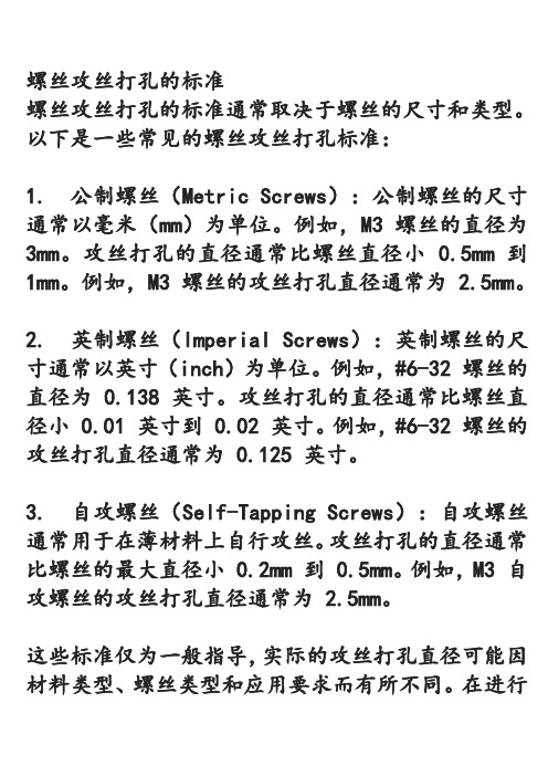
螺丝攻丝打孔的标准
螺丝攻丝打孔的标准通常取决于螺丝的尺寸和类型。
以下是一些常见的螺丝攻丝打孔标准:
1. 公制螺丝(Metric Screws):公制螺丝的尺寸通常以毫米(mm)为单位。
例如,M3 螺丝的直径为3mm。
攻丝打孔的直径通常比螺丝直径小 0.5mm 到1mm。
例如,M3 螺丝的攻丝打孔直径通常为
2.5mm。
2. 英制螺丝(Imperial Screws):英制螺丝的尺寸通常以英寸(inch)为单位。
例如,#6-32 螺丝的直径为 0.138 英寸。
攻丝打孔的直径通常比螺丝直径小 0.01 英寸到 0.02 英寸。
例如,#6-32 螺丝的攻丝打孔直径通常为 0.125 英寸。
3. 自攻螺丝(Self-Tapping Screws):自攻螺丝通常用于在薄材料上自行攻丝。
攻丝打孔的直径通常比螺丝的最大直径小 0.2mm 到 0.5mm。
例如,M3 自攻螺丝的攻丝打孔直径通常为 2.5mm。
这些标准仅为一般指导,实际的攻丝打孔直径可能因材料类型、螺丝类型和应用要求而有所不同。
在进行
螺丝攻丝打孔时,最好参考相关的螺丝规格表和材料制造商的建议,以确保选择正确的攻丝打孔尺寸。
TAPTITEII三角自攻螺丝标准DUO-TAPTITE CORFLEX ?DUO-TAPTITEReduced In-Place Cost!!TAPTITE II ? and DUO-TAPTITE ? thread rolling screws reduce in-place fastener costs and provide vibration resistant assemblies. TAPTITE II ? and DUO-TAPTITE ? thread rolling screws are used to create strong, uniform load carrying internal threads into untapped nut members upon installation. When REMINC developed the original TAPTITE ? TRILOBULAR? shape thread rolling screw, it revolutionized the use of threaded fasteners in high production assembly. Assembly efficiency and joint performance along with lower in-place fasten-ing cost, havebeen the benefits of using TAPTITE ? screws. TAPTITE II ? and DUO-TAPTITE ? screws and bolts continue these benefits along with meeting the quality and performance needs of the future.Lower In-Place Fastening CostsOnly 15% of the total in-place cost of a fastening is the cost of the screw or bolt. TAPTITE II ? and DUO-TAPTITE ? screws and bolts lower the cost of the remaining 85%.The following is a list of some of the cost-savings advantages of using TAPTITE II ? and DUO-TAPTITE ? thread rolling screws.-Elimination of separate tapping operations and associated costs. -Built-in resistance to vibrational loosening eliminates the need for lock washers, adhesives, or plastic patches and plugs. - Generates stronger mating threads with uninterrupted grain flow due to work hardening of the nut for higher stripping resistance. -Accepts larger pilot hole variations than drilled and tapped holes. -Works in punched, drilled, cored and extruded holes in many different metals. -With use of CORFLEX ? metallurgy, can be provided in grade strengths of high tensile bolts for use in struc-tural applications in deep thread lengths of engagement. -No assembly line cross threading. -Prevailing torque often equals or exceeds locking screw standards. - Manufactured to REMINC standards all over the world by over 68 of the world’s leading fastener, fastenerprocessing and tooling companies.Originators of the TRILOBULAR? Family of Fasteners Providing Technical Support, Marketing Support and Innovative Fastener DesignCOPYRIGHT 2001, Research Engineering & Manufacturing Inc.level bolts are required. COPYRIGHT 2001, Research Engineering & Manufacturing Inc.Why TAPTITE II ? Over TAPTITE ?Screws? TAPTITE II ? screws bring benefits to both fastener manufacturer and end user. TAPTITE II ? screws were designed to: - Provide a more efficient manufacturing method and tool design to result in a more consistent product.- Be applicable to the quality and SPCphilosophies of today’s market by utilizing the capabilities of today’s state of the art tooling and fastener manufacturing equipment. - Provide more consistent torque performance, lowerthread forming torque and lower end load necessary to initiate thread forming, thanany other thread forming or thread rollingscrew including the original TAPTITE ? screw.Behind the scenes, REMINC has provided its licensed manufacturers with a total quality system for manu-facturing TAPTITE II ? fasteners. Included are design and processing failure mode and effects analysis pro-cedures, statistical in process control data collectionsystem, and improved inspection procedures and cri-teria. Although all REMINC products are designed for consistent manufacture and performance, TAPTITE II ? fasteners were physically re-designed tomeet the above quality system, to be the quality flag-ship of TRILOBULAR? products.Note: TAPTITE II ? is often designated TYPE TT AND TT-II“The Controllable Product ?”COPYRIGHT 2001, Research Engineering & Manufacturing Inc.Better starting stability – Axial AlignmentLess misalignment at start of driving operation . . . the self-aligning characteristic of DUO-TAPTITE ? screws reduces operator fatigue; eliminates interruptions in produc-tion; adds speed to every fastening opera-tion. Suitable for automated and robotic assembly. B – Higher prevailing torque Superior elastic action of a DUO-TAPTITE ? screw gives it better lock-ing characteristics than many fasteners specifically designed aslocking screws! Competitive round-bodied, thread-forming fasteners have nolocking torque. Graph shows comparison of DUO-TAPTITE ? screw with IFI-124 minimum requirement for self-locking screws.TYPICAL ANGULARITYLower starting end pressureLower starting end pressure combines with lower driving torque to reduce time and power costs right down the line. A –Higher strip-to-drive ratio The higher, more uniform, strip-to-drive torque ratio of DUO-TAPTITEscrews pro-vides a built-in safety factor against over-driving. Eliminates broken screws, dam-aged mating threads and inferior fastenings.Torque-tension comparison M8 x 1.25 DUO-TAPTITE ? vs.TAPTITE ? FastenerSuperior tension at any given applied torque (with normal clamping pressure) is a major factor in the better holding capa-bility of a DUO-TAPTITE ? screw.NOTE: All screws were tested in unthreaded weld nuts of uniform hardness (Rockwell B 82-84) hav-ing 7.1mm hole diameters. End pressure wasmanually developed, measured and recorded by anelectronic load cell and recorder. Drive, prevailingand strip torque values, and torque-tension valueswere measured with a GSE torque cell and re-corded on a BLH electronic recorder. All test datais based on 5/16 - 18 or M8 x 1.25 screws.COPYRIGHT 2001, Research Engineering & Manufacturing Inc.Suggested hole sizes for TAPTITE II ? & DUO-TAPTITEScrews and Bolts at various percentages of thread engagementEXAMPLE - The shaded areaindicates that an M5 - 0.8 screw size in a 4.58 hole size provides 80% threadengagement.Because the above values are based on a linear relation between hole size and percentage thread engagement, the hole data becomes less accurate for engagements less than 70%.Note also, these hole sizes are based on the U.S. basic thread depth of .6495 times the pitch and are calculated using nominal screw diameters.Hole = D - (0.6495 x P x %), where D = nominal screw diameter.(1) Pilot holes listed under 90% & 85% (Thread Percent) also recommended for single punch extruded holes.See Page 11For Pilot Hole Tolerance in terms of thread percentage, we suggest +5% to -10% of the nominal value, percent thread value.EXAMPLE: If 80% is the percent thread for the nominal hole, the minimum hole would yield 85% thread and themaximum hole would yield 70% thread.COPYRIGHT 2001, Research Engineering & Manufacturing Inc.Recommended pilot hole sizes forTAPTITE II ? & DUO-TAPTITE ?Screws and Bolts for steel nut member thicknesses (Expressed in terms of screw diameters)APPLICATION DUTY CLASS - A general term used here to group material thickness in terms of screw diameters. For example, the average material thicknesslisted under "medium-heavy" equals 75% of the screw diameter.COPYRIGHT 2001, Research Engineering & Manufacturing Inc.NOTES: - Torque values for metric sizes in New-ton-meters - Torque values for inch sizes in pound-inches - Plate dimensions for metric sizes in mil-limeters and for inch sizes in inches - Torque values were developed using hex washer head screws,zinc plated plus lubricity wax, driven at low speed underlaboratory-controlled conditions. - Values shown represent the above con-ditions only and should not be used in lieu of proper application testing. The data is presented to provide the user with an estimate of what could be achieved in an actual application having a thicker or thinner nut member harder or softer material, different hole or fas-tener all contribute to variations in torque performance. - Recommended tightening torque is in-tended to induce approximately 30,000 to 50,000 psi clamping force. - Prevailing first removal torque, the torque necessary to remove the screw after the head has been un-seated, is an indication of TAPTITE II ? screws inherent resistance of free turning which is an indication of resistance to loosen-ing under vibration, even without screw head being seated. * Indicates probability that nut threads will strip. ? Indicates probability that screw will break.COPYRIGHT 2001, Research Engineering & Manufacturing Inc.The above hole sizes are suggested starting points to be confirmed by actual testing. Extrusion Dimensions can vary due to tooling design and material being extruded.Approximate Material Thickness "T"Suggested extruded holes in light-gauge steel for TAPTITE II ? and DUO-TAPTITE ?Screws & Bolts (Continued from page 11)COPYRIGHT 2001, Research Engineering & Manufacturing Inc.Lengths greater than 25mm ± 1.3mmCOPYRIGHT 2001, Research Engineering & Manufacturing Inc.Self-aligning point feature‘finds’ the holes, lines them upand fastens them in oneoperation.COPYRIGHT 2001, Research Engineering & Manufacturing Inc.TEST PARAMETERS -Test material: cold-rolled draw qualityaluminum killed steel platehardened to Rb 50-55Test washer: .063 thick steelClearance hole: .180(#6), .200(#8), .220(#10),.280(1/4”)Drive speed: 250 RPM under loadDriver end load: 8lbs.- These values may vary proportionately to application.Smaller hole sizes for example, will increase drive, first off,strip torques, etc. Material thickness will also effect torque/ tension values as indicated in the table. These values were derived from averages of over 1800 laboratory tests under specific conditions. These values are to be used only as aguide since actual application performance results may vary.Reusable - Subjecting the POWERLOK? screw to increasingclamp load results in continuously in-creasing thread flankcontact so that unit pressure between mating surfaces tends to remain constant, an important factor in diminishing galling and abra-sion. Together with the burnishing action of the TRILOBULAR? crests means continued locking ef-fectiveness, after repeated insertions and removals. Locking performance - Will meet or exceed IFI 124 (inch) or IFI 524 (metric) Specifications for Pre-vailing Torque Locking Screws. Transverse vibration test data available upon request. Actual perform-ance will vary depending on effective finish lubricity and nut condition.No special taps - You save time and money by using a regular nut or Class 2B (6G) tapped hole. POWERLOK? is precision made - so the hole thread doesn’t have to be. Applications - Widely used in automotive and other mass-assembly operations. You can use POWERLOK?screws wherever you need reliable vibration resistance, continued high performance, despite repeated assem-bly/disassembly using normal tapped holes. They can be used in pre-tapped holes in ductile metals. STANDARD MATERIAL - Depending on part size, low carbon, medium carbon or alloy steel is selected. Then the steel is hardened and tempered to the optimum combination of tensile strength and toughness. Ten-sile or torsional strength can be more than twice that of machine screws. Screws can be made in strength levels to suit a wide range of application requirements. Property Class 10.9 is often preferred. Finishes can be supplied as required.The PLASTITE ? family of TRILOBULAR? screws for fastening in plastic The following is intended as a guide tochoosing threaded fasteners which will provide optimum application and per-formance characteristics in a wide range of plastics. It contains detailed information on PLASTITE ? thread- rolling screws. Because of the variations in the manu-facture of individual grades of plastics,particularly in the quantity of filler used, it is imperative that tests be conducted on each proposed application by a com-petent engineering laboratory. REMINC/CONTI’s network of licensees provide this testing service usually wit out obligation. This provides the design engineer with recommendations in the following areas: type of fasteners,quantity and sizes, design of the fasten-ing site or boss, hole sizes. Torque val-ues needed for power tool settings dur-ing assembly, including: drive, strip, seating, breakaway and prevailing off torque. A written report on the test re- sults is usually provided.How the TRILOBULAR? familyoptimizes fastener performance and lowers in-place costs. PLASTITE ? TRILOBULAR? thread-rolling screws were developed specifi-cally for use in plastics. They combine a unique TRILOBULAR? cross-sectionalform with deep, wide, spaced threads. Easier to drive. Three swaging lobes with full relief of the thread form reduce driving effort and operator fatigue. More holding power . The three-lobed design of PLASTITE ? screws takes full advantage of the cold flow characteris-tics of many plastics by allowing plastic material to recover and fill in between the lobes. This establishes maximum resistance to vibrational loosening. In addition, the screws’ deep, coarselyspaced threads provide a heavier shear area and deeperthread engagement in the plastic, further enhancing holding capabilities. COPYRIGHT 2001, Research Engineering & Manufacturing Inc.Size #2-#12Sizes M2-M5FINISH:Over 3/4"± .050"Over 20mm ± 1.3As Requested Over 1/4" Dia.M6-M8All Lengths ± .050"All Lengths ± 1.3COPYRIGHT 2001, Research Engineering & Manufacturing Inc.COPYRIGHT 2001, Research Engineering & Manufacturing Inc.1. Size/TPI –The PLASTITE ? 48-2 screw size designation combines the commonly used numerical screw size with the major diameter (Max. “D”) as measured with ordi-nary micrometers, followed by thenumber of threads per inch. 2. Recommended pilot hole sizes are subject to variation dependent on depth of engagement, ease of driving required and material being tapped. Users of PLASTITE ? 48-2 screws should perform their own test to determine the most efficient pilot hole size for their own particular use, or contact the appli-cation engineering department of a qualified supplier or REMINC.MATERIAL:Low Carbon Steel,Suitably Hardened and Tempered FINISH:As Requested LENGTH TOLERANCES Nom.Length Tol.Thru 3/4"± .030"Over 3/4"± .050"Over 1/4" Dia.All Lengths ± .050"。