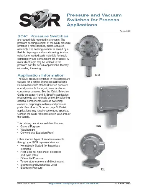
Pressure and Vacuum Switches for Process ApplicationsForm 216SOR ® Pressure Switchesare rugged fi eld-mounted instruments. Thepressure sensing element of the SOR pressure switch is a force-balance, piston-actuated assembly. The sensing element is sealed by a fl exible diaphragm and a static o-ring. A wide selection of wetted parts materials for media compatibility and containment are available. A metal diaphragm may be welded to thepressure port for certain applications, thereby eliminating the o-ring.Application InformationThe SOR pressure switches in this catalog are suitable for a variety of process applications. Basic models with standard wetted parts are normally suitable for air, oil, water and non-corrosive processes. See the Quick Selection Guide on pages 4 and 5. Specifi c application requirements can normally be met by selecting optional components, such as switching elements, diaphragm systems and pressure ports. See How to Order on page 3. Certain applications may require customized specials. Consult the SOR representative in your area or the factory.This catalog describes switches that are: • General Purpose • Weathertight• Conventional Explosion ProofOther specifi c types of switches available through your SOR representative are:• Hermetically Sealed (for hazardous locations)• Pivot Seal (for high shock pressuresand cycle rates)• Differential Pressure• Temperature (remote and direct mount)• Electronic and Mechanical Level • Electronic Pressure12L6B36NNFeatures SwitchesComplete Product LineStandard models and customized specials cover pressure range from30 inches Hg VAC to 4000 psi.Robust ConstructionRugged, high-cycle rate tolerance, long life, not critical to vibration, high overrange and proof pressures, excellent corrosionresistance to hostile environments. Instrument QualityHigh resolution of Set Points, high repeatability, narrow dead band,negligible temperature effect.Wetted PartsWide selection materials, process connection confi gurations and sizes.Optional “fi re-safe” pressure sensor.Snap-Action Electrical SwitchingWide selection UL Listed and CSA Certifi ed switching elements for ACand DC service. Optional “hermeticallysealed” capsule for hazardous and hostile environments.Field AdjustableSelf-locking adjustment, no special tools required. No-charge factory calibration.Cost EffectiveSimple and fast installation without special tools, long service life, norequired periodic service or spareparts.UL Listed, CSA Certifi ed, ATEXCertifi ed, FM, JIS/RIIS Approved ModelsMeets most code and customer requirements.Built-In QualityRigid quality standards maintained from raw material to fi nished product.ServiceFactory sales engineers and area SOR representatives provideeffective and prompt worldwideservice.DeliveryRoutine shipments 7 to 10 working days. Emergency shipments via sameday air.Warranty3 years from date of manufacture.Quick Selection GuideBasic SOR pressure switches with standard wetted parts are normally suitable for air, oil, water and non-corrosive processes. The Quick Selection Guide on pages 4 and 5 shows these basic SOR pressure and vacuum switches. Corrosive service and particular customer requirements may require optional components. Refer to How to Order section below to build a customized model number or the dedicated page to locate optional components, such as switching elements, diaphragm systems, pressure ports and accessories. Each position in the model number, except Accessories, must have a designator.Design and specifi cations are subject to change without notice. For latest revision, see .6NN-K5-M4-C2A-YYModel Number SystemDiaphragmHousingPistonSwitching Element Range SpringPressure PortAccessoriesApplicationsSOR pressure switches in this catalog are suitable for a wide variety of continuous pressure applications. Specifi c application requirements can normally be met by selecting optional components, such as, switching elements, diaphragm systems and pressure ports. Certain applications may require customized specials. Consult the SOR representative in your area or the factory.How to OrderInformation and data in this catalog are formatted to provide a convenient guide to assistinstrument engineers, plant engineers and end users in selecting pressure switches for their unique applications.Steps 1 through 5 are required. Step 6 is optional. Orders must have complete Model Numbers, i.e. each component must have a designator.Step 1: Select Piston-Spring adjustable range/Set Point from Specifi cations (pages 7 & 8). (Piston/Spring combination determines adjustable range.)Step 2: Select Housing for type of pressure switch and service (page 9).Step 3: Select electrical Switching Element for electrical service (pages 10 & 11).Step 4: Select Diaphragm and O-Ring for process compatibility and containment (pages 12 & 13).Step 5:Select Pressure Port for process compatibility and connection (page 14).Step 6: Select Accessories required for service (page 16).How to OrderSwitchesExplosion ProofWeathertightBasic SOR pressure switches with standard wetted parts are normally suitable for air, oil, waterand non-corrosive processes. Corrosive service and particular customer requirements may require optional components. Refer to How to Order on page 3 to locate optional components, such as, housing, switching elements, diaphragm systems, pressure ports and accessories. Each position in the model number, except Accessories, must have a designator.WeathertightExplosion ProofStandard Construction• Housing: NN - aluminum; L - cast iron• Switching Element: SPDT; N - 10 amps @ 250 VAC; K - 15 amps @ 250 VAC• Diaphragm & O-ring: N4 - primary (wetted)diaphragm, TCP; o-ring (wetted) Buna-N• Pressure Port: 1/4” NPT(F); B1A - aluminum; F1A - carbon steelNotes1. See balance of catalog for construction options.2. Dead band values are expressed as typical expected at mid-range for a particular model number. See Dead Band Considerations on page 8.3. Design and specifi cations subject to changewithout notice. For latest revision, see.Standard Construction• Housing: NN - aluminum; L - cast iron• Switching Element: SPDT; K - 15 amps @ 250 VAC• Diaphragm & O-ring: N4 - primary (wetted)diaphragm, TCP; o-ring (wetted) Buna-N• Pressure Port: 1/4” NPT(F); B1A - aluminum; F1A - carbon steelNotes1. See balance of catalog for construction options.2. Dead band values are expressed as typical expected at mid-range for a particular model number. See Dead Band Considerations on page 8.3. Design and specifi cations subject to change without notice. For latest revision, see .WeathertightExplosion ProofExplosion ProofWeathertightStandard Construction• Housing: NN - aluminum; L - cast iron• Switching Element: SPDT; K - 15 amps @ 250 VAC • Diaphragm & O-ring: N4 - primary (wetted) diaphragm, TCP; o-ring (wetted) Buna-N. Piston 56 primary (wetted) diaphragm, 316SS.• Pressure Port: 1/4” NPT(F); B1A - aluminum; F1A - carbon steelNotes1. See balance of catalog for construction options.2. Dead band values are expressed as typical expected at mid-range for a particular model number. See Dead Band Considerations on page 8.3. Design and specifi cations subject to change without notice. For latest revision, see .Quick Selection Guide - VacuumPressure SwitchA bi-stable electromechanical device that actuates/deactuates one or more electrical switching element(s) at a predetermined discrete pressure/vacuum (Set Point) upon rising or falling pressure/vacuum.Adjustable RangeThe span of pressure between upper and lower limits within which the pressure switch can be adjusted to actuate/deactuate. It is expressed for increasing pressure.Set PointThat discrete pressure at which the pressure switch is adjusted to actuate/deactuate on rising or falling pressure. It must fall within the adjustable range and be called out as increasing or decreasing pressure.Dead BandThe difference in pressure between theincreasing Set Point and the decreasing Set Point. It is expressed as typical, which is an average with the increasing Set Point at mid-range for a pressure switch with the standard K switching element. It is normally fi xed (non-adjustable).Fire-SafeThe ability of a welded seal pressure sensor to contain the process at elevated temperatures up to 1200°F at the rated overrange pressure, unsupported by the body of the pressure switch.Hermetically SealedA welded steel capsule with glass-to-metal, factory-sealed electrical leads that isolates the electrical switching element(s) from the environment.OverrangeThe maximum input pressure that can be continuously applied to the pressure switch without causing permanent change of Set Point, leakage or material failure.SwitchesGlossary of T ermsSOR recognizes that there is no industry convention with respect to terminology and defi nitions pertinent to pressure switches. This glossary applies to SOR pressure switches.Proof PressureThe maximum input pressure that can be continuously applied to the pressure switch without causing leakage or catastrophic material failure. Permanent change of Set Points may occur, or the device may be rendered inoperative.RepeatabilityThe ability of a pressure switch to successively operate at a Set Point that is approached from a starting point in the same direction and returns to the starting point over three consecutive cycles to establish a pressure profi le.Repeatability on SOR switches will be smaller than 1% of full scale per ISA/ANSI S51.1. SPDT Switching ElementSingle-Pole, Double Throw (SPDT) has three connections: C — Common, NO — Normally Open and NC — Normally Closed, whichallows the switching element to be electrically connected to the circuit in either NO or NC state.DPDT Switching ElementDPDT is two synchronized SPDT switching elements which actuate together at increasing Set Point and deactuate together at decreasing Set Point. Discrete SPDT switching elements allow two independent circuits to be switched; i.e., one AC and one DC.The synchronization linkage is factory set, and is not fi eld adjustable. Synchronization is verifi ed by connecting test lamps to the switching elements and observing them go “On” simultaneously at actuation and “Off” simultaneously at deactuation.6NN-K5-M4-C2A-YY This table is a listing of piston-spring combinations and the corresponding adjustable ranges, dead bands, overrange and proof pressures. Adjustable range is expressed for increasing pressure; the Set Point must be within the adjustable range. Dead band is expressed as typical. See Dead Band Considerations on page 8.1. Dead band values are expressed as typicalexpected at mid-range with the standard Kswitching element assembly installed. Whenoptional switching elements are specifi ed,corresponding dead band multipliers shownon pages 8 and 10 must be applied.2. The 12/66 piston/spring combination isavailable with the N switching element only.3. Adjustable range becomes 10 to 45 in. wcwhenever switching elements other than K, KA,W or D are used.4. Special ranges may be possible. Consult thefactory or the SOR representative in your area. 5. Diaphragms may have an additional effect ondead band. See page 13, Note 9.6. Diaphragm life may be limited by using T or Hswitching elements with Numbers 1 and9pistons.7. Metric bar (mbar) values are practicalequivalents of the reference English values; notnecessarily exact mathematical conversions.This data appears on the product nameplatewhen metric engineering units are specifi ed.8. A breather drain (Accessory KK, see page 16)should be specifi ed when low pressureadjustable ranges are used in environmentswith signifi cant ambient temperature changes.9. Filled isolators attached to the pressure switchwill affect dead band.This table is a listing of piston–spring combinations and the corresponding adjustable ranges, dead bands, overrange and proof pressures. SOR vacuum switches are compound; they will operate in either vacuum or pressure modes. Adjustable range is expressed from maximum vacuum decreasing to zero gauge andincreasing to maximum pressure. Dead band is expressed as typical. See dead band considerations below. The Set Point must be within the adjustable range. A vacuum switch is generally better suited than a pressure switch for Set Points very near zero gauge.Notes1. Dead band values are expressed as typical expected at mid-range with the standard K switching element assembly installed. When optional switching elements are specifi ed, corresponding dead band multipliers shown below must be applied.2. Special ranges may be possible. Consult the factory or the SOR representative in your area.3. Diaphragms may have an additional effect on dead band. See page 13, Note 9.4. Metric bar (mbar) values are practical equivalents of the reference English values; not necessarily exact mathematical conversions. This data appears on the product nameplate when metric engineering units are specifi ed.1. Dead band values are expressed as typical expected atmid-adjustable range using the standard K switching element. When optional switching elements are specifi ed, corresponding dead band multipliers must be applied.2. Dead bands are fi xed (non-adjustable), except when T or H switching elements are used.3. Dead band can be adjustable by selecting T or H switching element. (Diaphragm life may be limited when used with Numbers 1 and 9 pistons.)4. Dead band multipliers must be applied to the typical dead band value shown for piston-spring combination in specifi cations, pages 7 and 8, whenever optional switching elements other than K, KA or W are used.5. Dead band can be widened by selecting an optional switching element with a multiplier greater than 1.0. Example: Model 6NN-G5-M4-C2A-YY Typical Dead Band 1.4 psi G-Switching Element multiplier = 3 Corrected Typical Dead Band 1.4 x 3 = 4.2 psi6. See item #9, page7.Dead Band Considerations52NN-K 116-M4-C2A-YYClass II, Group E, F, & G; Divisions 1 *L*S*LC*T A*J4NNN6P3Electrical: 3/4” NPT(F) - Left, Right Material: AluminumSee Agency Listings pages 17 & 18.See Switching Element Groups 1, 2, 3 & 4 below.N3N4RN RBSwitchesStep 2: Housing*BD only available with RN, RT housings.*C micro switch is not available in L, S and TA housings.*CA micro switch only available in PP, NN, N3 and N4 housings.Switches Step 3: Switching Element6NN-K5-M4-C2A-YYCross reference compatibility chart on page 9 to ensure that switching element will fi t in housing. Review notes on page 11 for more details.SwitchesStep 3: Switching Element6NN-K 5-M4-C2A-YYNotes1. Double switching elements have wire leads except when supplied in housings RB, RM, RN, RS, RT, B3, B4, B5, B6 and J4. Terminal blocks are standard in these housings.2. Dead band multipliers must be applied to thetypical dead band fi gures given in the specifi cation tables on pages 7 and 8.3. Switching element ambient temperature limits:-65 to 400o F (-54 to 200o C) B, Y, W-65 to 250o F (-54 to 120oC) A, E, & J-40 to 167o F (-40 to 75oC) AF, AG, E F , EG,JF, JG-13 to 158o F (-25 to 70o C) BD-65 to 180o F (-54 to 80o C) All others4. The hermetically sealed switching elementcapsule is ATEX Approved, UL Listed, CSA Certifi ed and SAA Approved as an explosion-proof snap switch according to the following table with conditions and exceptions specifi ed in Note 3.5. Switching elements W, & Y have Elgiloy springs.6. Certain switching elements can handle greater voltage and/or amperage. Consult the factory should your requirements exceed catalog values. All switching elements above except BD are UL Recognized and CSA Certifi ed. The DC current ratings marked with an asterisk (*) are not UL Listed but have been verifi ed by testing and/or experience.7. Ambient temperature is reduced to 200°F (93°C) for J, JJ, A, AA, E, EE, B, BB, Y, YY, & W switching elements when CV accessory is selected.CAUTION: The switching element assemblyhas been precisely positioned in the housing at the factory for optimum performance. Any inadvertent movement or replacement in the fi eld will degrade performance, could render the device inoperative, and can void the warranty unless factory authorized proceduresare followed.Notes Array1. N4 diaphragm system is standard, but requiresa designator in the model number. It is normallysuitable for air, oil, water and noncorrosiveprocesses. M2 diaphragm system is standardon Number 56 vacuum switches. (See notes10 & 13.)2. U7 designates a welded fl ush-type diaphragm.Available only in 1” NPT(M) 316SS onNumbers 5 & 6 pistons with K switchingelement. See page 15.3. U8 designates the welded fi re-safe diaphragmsystem. 316SS is stocked. Not available onNumber 1 piston or vacuum switches.Example: U8-C2A is a 316SS fi re-safe weldeddiaphragm system. See page 15.4. U9 designates a welded diaphragm system.Not available on vacuum switches.Example: U9-A1A is a Monel weldeddiaphragm system. See page 15.5. Other diaphragm and o-ring combinations maybe available. Consult the factory or the SORrepresentative in your area for more information.6. Wetted parts have been selected asrepresenting the most suitable commerciallyavailable material for use in the service intended.However, they do not constitute a guaranteeagainst corrosion or permeation, since processes vary from plant to plant and concentration ofharmful fl uids, gases or solids vary from time totime in a given process. Empirical experienceby users should be the fi nal guide. Alternatematerials are generally available.(Continued on page 13.)7. N3 diaphragm system utilizes a durableback-up diaphragm for high cycle-rate, highshock applications where Buna-N and TCP are compatible with the process. Consult factory if process temperatures are well below freezing.8. This table shows allowable minimum andmaximum temperatures for o-rings. Consult the factory for temperatures down to –65°F onfi re- safe and welded metal diaphragmsystems.9. Dead bands are slightly higher when usingH, J, N3, N6, U or W series diaphragmoptions. Consult the factory.10. Diaphragm systems N1, N3, N4, N5, N6, N7,N8, P1, R1, S1, S2, W2, W4, W5, W6, Y1,U8, U9 are not available on Number 56vacuumswitches.11. M9 diaphragm system is suggested for steamapplications up to 400°F.12. If Kalrez, EPR or Viton is selected for hightemperature process media or ambienttemperature requirements, the A, B, E, J, W or Y switching elements are suggested withreference to the table in Note 3, page 11. 13. Only diaphragm systems N1, N4, N5, N7, N8and P1 are available on the 12-66 piston-springcombination.SwitchesStep 5: Pressure Port6NN-K5-M4-C2A -YYNotes1. Select designators for material and connection size. Large bold-face letters denote those items generally available from stock. Small light-face letters denote items with limited stock and possible long delivery.2. 1/4” and 1/2” tapered BSP(F) pressure ports are available. Consult factory.3. Combinations are possible when a particular connection size is not available for the range (piston/spring) desired. For example, if 2” NPT(F) is desired for a Number 4 piston, the Number 12 pressure port can be supplied. The piston would be designated as Number 124 and the overrange and proof pressures for Number 12 apply. Note: 124, 125 and 126 are the only available combinations.4. Many other materials such as PVC, Kynar, etc., are available. Denote materials not shown by specifying an X followed by the required connection size, and describe the material.Examples:X2A = PVC pressure port with 1/2” NPT(F) connection.X1A = Titanium pressure port with 1/4” NPT(F) connection.Non-metal pressure ports generally reduce proof pressure and may reduce overrange pressure. The pressure port material may limit the process temperature. Delivery may be longer than normal.5. Raised-face and fl at-face fl anges to match ASA 150 and ASA 300 lb. in commercially available materials can be supplied on Series 12 and 4 pistons by adding an X suffi x to the model numbers and specifying “X - (size) inch (material) (raised- or fl at-) face fl ange to match ASA (rating) lb.”6. Brass not available on Piston Numbers 9 and 1.7. 1/4” NPT(F) Flushing Port standard on C6A pressure ports.*C4A only available with Pistons 5 & 6 when U7 diaphragm is specifi ed. See page 15.See next page for presentation of welded diaphragm and FM Approved fire-safe systems.Pressure and Vacuum SwitchesWelded Diaphragm & Fire-Safe SystemsFactory Mutual System Approved - U.S Patent Number 4,438,305Two-inch Pressure PortThe wide pressure port minimizes the possibility of clogging when the process media is sludgy or viscous. See page 20 for dimensions. A 2” NPT(F) pressure port with a 1/4” NPT(F) fl ushing port can be supplied with a welded diaphragm, or with a conventional diaphragm and o-ring combination.ConnectionPiston ShaftDiaphragmSwitches Step 6: Accessories6NN-K5-M4-C2A-YY*Consult the factory for materials other than 316/316L.CSATIISATEXBASEEFASOR Pressure Switches in this catalog may be specifi ed with manual reset electrical switching elements D or M. D actuates automatically on increasing pressure. M actuates automatically on decreasing pressure. Depress the button to manually reset. Housings must be RB (weathertight) or S (explosion proof) because of the requirement of a hub for the manual reset assembly. Refer to page 3 for How to Order instructions.Shipping WeightsManual Reset ButtonRB - Weathertight S - Explosion ProofSwitchesManual ResetActual shipping weights may vary from the charted values because of product material, confi guration and packaging requirements.NotePK Pipe Kit adds approximately 1.5 lbs. (0.7 kgs). TB Junction box adds approximately 5 lbs (2.25 kgs).Dimensions in this catalog are for reference only. They may be changed without notice. Contact the factory for certifi ed drawings for a particular model number.Notes 1. Dimensions in this catalog are expressed as millimeters over inches (Linear = mm/in.). 2. Dimensions marked with an asterisk (*) on housing dimension drawings (pages 20 through 31) vary with respect to process connection size. The chart below lists these dimension variances. 3. Electrical Connection Size: 3/4” NPT(F) standard. 1/2” NPT(F), 1/2” NPT(M), M20 x 1.5, PG 13.5, PF 3/4” optional. Consult the factory for compatibility with selected housing or agencylisting.DimensionsSwitchesDimensionsDimensions in this catalog are for reference only. They may be changed without notice. Contact the factory for certifi ed drawings for a particular model number.Wide Pressure Port: C6ASee description on page 15.Pipe Mounting Kit: PKDrawing # 0091354Drawing # 0090300Drawing # 0091353Junction Box with T erminalBlock:TBDimensions in this catalog are for reference only. They may be changed without notice. Contact the factory for certifi ed drawings for a particular model number.Weathertight - NEMA 4, 4X, IP65Housing PP, P3 and PF are General Purpose.(Cover gasket is not installed.)Dimensions in this catalog are for reference only. They may be changed without notice. Contact the factory for certifi ed drawings for a particular model number.Piston Numbers 5, 6, 1, 9, 56Dimensions in this catalog are for reference only. They may be changed without notice. Contact the factory for certifi ed drawings for a particular model number.Open BracketDesignators: H3Piston Numbers 5, 6, 9, 1, 56Drawing # 0090027Dimensions in this catalog are for reference only. They may be changed without notice. Contact the factory for certifi ed drawings for a particular model number.Weathertight - NEMA 4, 4X, IP65Designators: N6Piston Numbers Drawing 0090020Dimensions in this catalog are for reference only. They may be changed without notice. Contact the factory for certifi ed drawings for a particular model number.Conventional Explosion ProofDimensions in this catalog are for reference only. They may be changed without notice. Contact the factory for certifi ed drawings for a particular model number.Conventional Explosion ProofDesignators: SPiston Numbers 5, 6, 9, 1, 56Drawing # 0090147Dimensions in this catalog are for reference only. They may be changed without notice. Contact the factory for certifi ed drawings for a particular model number.Conventional Explosion ProofPiston Numbers 5, 6, 9, 1, 56SC shown. LC identical except right-handelectrical connection only.Dimensions in this catalog are for reference only. They may be changed without notice. Contact the factory for certifi ed drawings for a particular model number.Conventional Explosion ProofPiston Numbers 5, 6, 9, 1, 56Dimensions in this catalog are for reference only. They may be changed without notice. Contact the factory for certifi ed drawings for a particular model number.Explosion ProofDimensions in this catalog are for reference only. They may be changed without notice. Contact the factory for certifi ed drawings for a particular model number.Weathertight - NEMA 4, 4X, IP65Drawing # 0090271Designators: RB Manual ResetPiston Numbers 5, 6, 1, 9, 56Pressure and VacuumSwitches Dimensions Dimensions in this catalog are for reference only. They may be changed without notice. Contact the factory for certifi ed drawings for a particular model number.Conventional Explosion ProofDrawing # 0090169Designators: S Manual ResetPiston Numbers 5, 6, 1, 9, 56*Refer to Dimensions table on page 19 for changes in length due to process connection size, including A dimension.Registered Quality System to ISO 9001:200032/32Form 913-888-2630echOsonix Level TransmittersT emperature SwitchesP r e s s u r eFlowLevelLevel SwitchesFlow SwitchesPressure SwitchesSOR ®offers a full line of commercial-grade process instruments.TemperatureRegistered Quality System to ISO 9001:2000Form 216 (04.08) ©2008 SOR Inc.We Deliver Quality On TimeSOR Europe, Ltd.Star RoadPartridge Green, Sussex RH13 8RA, United Kingdom Phone +44-140-371-1331Fax +44-140-371-0177sales@SOR - ChinaRoom 903, No. 10 Building Wan Da PlazaNo. 93 Jian Guo Road Chao Yang District Beijing, China 100022Phone +86 (10) 5820 8767Fax +86 (10) 5820 8770SOR Inc.14685 West 105th Street Lenexa, Kansas 66215Phone 913-888-2630Toll Free 800-676-6794Fax 913-888-0767Process Instrumentation。