3S压力开关使用说明书
- 格式:doc
- 大小:38.00 KB
- 文档页数:2
操作手册压力继电器(压力开关)YSJ-340系列一、概述YSJ-340系列压力继电器是一种超小型压力控制仪表,用于液压、气动系统的压力显示与控制,可替代德国贺德克HYDAC(贺德克)EDS300系列压力继电器。
该仪表采用了高精度压力传感器,电路部分以高性能单片机微处理器为核心,具有3位LED数字显示及轻触开关输入的人机界面、具有开关量(报警)输出及4~20mA模拟输出,是在机械继电器无法胜任的条件(如压力剧烈波动、强环境振动、高精度高速度控制、小体积等)下可靠工作的理想选择。
二、性能指标◇测量范围:0~1.6—0~60MPa◇电源电压:16~36VDC◇输出信号:(RL≤250Ω)◇接口螺纹:G1/4◇环境条件:环境温度:-20℃~60℃介质温度::-20℃~80℃存储温度 :-40℃~125℃相对湿度:0~80%耐冲击:≤50g/ms耐振动:≤10g/(0~500HZ)◇输出信号精度:1.0◇过载压力:1.5%倍满量程压力◇最大功耗:≤3W触点容量:24VDC/1.2A(MAX)三、功能根据不同型号,装置可提供下列功能◇三位显示当前压力(正常工作)◇按压力、预设开关点输出开关量◇输出模拟量◇基本设定菜单◇提供四种不同输出模式:◇YSJ341带1路开关量输出(负载最大电流1.2A,无模拟量输出)◇YSJ342带2路开关量输出(负载最大电流1.2A,无模拟量输出)◇YSJ343带1路开关量输出(负载最大电流1.2A)和1路模拟量输出(4~20mA)◇YSJ344带2路开关量输出(负载最大电流1.2A)和1路模拟量输出(4~20mA)四、安装YSJ340可以通过压力管接头(DIN3852内螺纹G1/4),直接装在液压集成快上。
电气连接必须由国家认定合格的电工操作(参考中国电工国家标准规范)。
压力继电器的外壳必须同时良好的接地。
如安装在液压块里,块体通过液压系统接地时有保证的。
若用微型软管安装,客体必须单独接地。
3S压差控制器
用途:
3S系列压差控制器,通常用于水,油系列中控制供液管与回液管的压差控制,一
种典型的应用是,把阀门安装在系统水(油)泵附近的旁通管路中,当系列液管二端的压差升高(或降低)而超过控制器设定值时,则阀门进而开大(或关小),从而系统液管二端的压差减小,达到系统的正常运行.
概述:3S系列压差控制器的两侧各有一个具有高灵敏感度的感压元件,元件二端的压力一旦变化,即引起开关机构动作来控制系统的设备.
电器参数:
电流电压COSA.C.125/250无诱导电流112满载电流0.7512瞬时电流0.4572
性能参
数: Mpa 型号调节范围开关差工厂设定压差最大工作压力
MinMaxOFFONJC15C0.03—0.2≤0.030.050.021.70JC2C0.01—0.150.050.03 0.0151.70JC35C0.05—0.350.10.10.051.70JC60CH0.1-0.600.10.350.403.30 注:以上控制器的接头螺纹均为M12*1.25.如果客户需要英制螺纹则须在型号后加缀“E”即可.一般采用的英制螺纹为7/16”-20UNF,另有延时功能的型号后加缀T需订做。
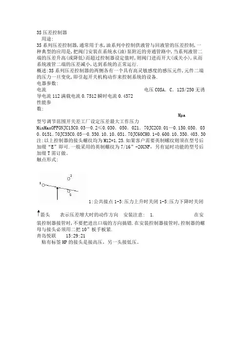
触点形式:
1:公共接点1-3:压力上升时关闭1-5:压力下降时关闭
箭头表示压差增大时的动作方向安装注意: 1. 在安装控制器接管
时,不要把进出口端的方向搞错.在安装控制器接管时,控制器的螺母与接头必须用二把10”板手板紧.
青岛悦联 15:29:21
贴有标签HP的接头是接高压,另一头接低压。

S3控制器简易手册(信息来自模拟器)一,菜单名称与定义:1,P00(默认菜单):显示空压机运行参数。
2,P01:标准设置菜单,用于更改常用空压机参数。
3,P02:故障历史记录查询。
4,P03:高级设置菜单,用于更改高级的空压机参数。
5,P04:工厂设置菜单,用于更改机组的工厂设置点。
6,P05:用于诊断和设置参数,检测模拟量的输入与输出。
7,P06:用于S3版本的升级与降级二,菜单密码:按“菜单键“后,进入密码提示栏,输入密码,按“上,下键”选择菜单,按“确认键“进入菜单。
1,P00不需要密码。
2,密码:0000,可进入:P00,PO1,P023,密码:0101,可进入:P00,P01,P02,P034,密码:1954,可进入:P00,P01,P02,P03,P045,密码:1594,可进入:P00,P01,P02,P03,P04,P05,P06备注:P00,P01,P02在开机状态下也可进入并修改。
P03,P04,P05,P06必须在停机状态下方可进入并修改。
只能将密码:0000告之客户。
三,P00菜单讲解:POO(默认菜单):相当于SE控制的DISPLAY键。
按“向上/向下键“在各项间进行转换。
1,Ae:主机排气温度2,Rn:运行时间3,Ld:加载时间4,Mn:距离维护的时间(此时间会随运行时间的增加而减少,到零时即到保养时间)。
5,Mn:%距维护的期限(此百分比也会逐渐减小)。
四,P01菜单讲解:相当于SE控制器的SET中的前几项。
P01:用于更改空压机的基本常用参数1,Un:调节卸载压力(上限),调整范围:(5.2BAR-----额定压力+0.2BAR)2,Ld:调节加载压力(下限),调整范围:(4.5BAR-----额定压力-0.4BAR)3,As:卸载运行到自动停车的时间(360S-3600S,0S可以设但不要设)。
4,Md:调节阀控制模式打开或关闭(ON/OFF),更改需要密码5,Eu:工程单位(度/BAR,度/KPA,度/PSI,华氏度/PSI)。
S-BSG-03-2B3A说明书
在遥控口使用遥控溢流阀DG-01产品,若遥控口管路的内部容积过大,易发生振动,故应该尽量减小管路内径和管路长度。
调整压力时,先松开锁紧螺母,顺时针旋转手轮,压力升高,反之压力降低,手轮每转一周,压力变化约5MPa,调定后,拧紧锁紧螺母。
压力调整会受到盐圈的限制,当达不到使用压力时,请拆下盛圈,每个垫圈月10MPa.
回油口管路不要与其他管路连接,应直接接回油箱。
小流量时,设定压力不稳定,公称尺寸为03,06时,使用流量应在5L/min以上,公称尺寸为10时,使用流量应在8L/min以上。
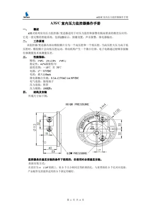
A3S/C室内压力监控器操作手册一、概述A3S/C系列室内压力监控器/变送器适用于对压力监控和报警有极高要求的微差压应用,它是一套完整的智能系统,包括LED显示,按键设置,声音报警,继电器输出。
二、工作原理该监控器/变送器内部由橡胶膜片分为一个高压腔和一个低压腔,当高压腔大压力高于低压腔时,橡胶膜片会向低压腔运动,带动机构产生一个微小位移,电子电路通过射频非接触位移测量技术来测量压差。
三、性能指标:精度:2%FS, (30-125Pa 4%FS )稳定性:±1%满量程/年温度范围:-10℃至50℃电源:17-35VDC电流:最大110mA继电器触点负载:0.5A 125V AC/1A 30VDC电气连接:接线端子压力连接:软管压力极限:100KPa四、结构及安装外观尺寸如下图:监控器是在垂直安装的条件下校准的,在使用时必须垂直安装。
表面安装方式:在直径为4 1/16"的圆上,钻3个大小相同且等距离的孔,与表背面的3个孔对应连接。
产品配件包里提供适用的3个固定用螺钉。
嵌入式安装方式:切下一个直径为4 9/16" 的圆,然后把表嵌入剩余部分的空隙中,并与适配器连接。
利用配件包中提供的6个螺钉将表固定在适当位置。
五、压力连接正压测量: 将压力管连接到表后面任意一个标有“high pressure”,即“高压”的孔,并堵塞另外一个高压孔。
把标有“low pressure”,即“低压”的两个孔暴露在大气中。
负压测量:把压力管连接到表背面任意一个标有“low pressure” ,即“低压”孔,并堵塞另外一个低压孔。
把标有“high pressure”,即“高压”的两个孔暴露在大气中。
差压测量: 把高压管连接到任意一个标有“high pressure”,即“高压”孔上,并堵塞另外一个高压孔。
把低压管连接到任意一个标有“low pressure”,即“低压”孔上,并堵塞另外一个低压孔。
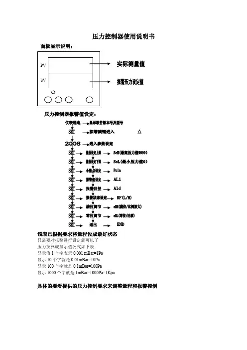
压力控制器使用说明书
面板显示说明:
该表已根据要求将量程设成最好状态
只需要对报警进行设定就可以了
压力换算成显示值公式如下表:
显示值1个字表示0.001 mBar=1Pa
显示10个字就是0.01mBar=10Pa
显示100个字就是0.1mBar=100Pa
显示1000个字就是1mBar=1000Pa=1Kpa
具体的要看提供的压力控制要求来调整量程和报警控制
压力开关原理及工作电路
气体的压力经过压力传感器转换成电流信号通过压力控制器的主CPU处理后显示在控制控制器的PV屏上。
控制的压力值显示在SV屏上,控制压力可以根据实际环境的要求设定,实现全智能控制模式。
继电器带有常开/常闭触点,可以根据现场的要求进行状态设定,以满足现场的要求。
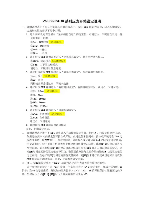
ZSE30/ISE30系列压力开关设定说明一、在测试模式下(即显示实际压力值的状态下)按住SET键2秒以上,进入初始设定。
完成初始设定需以下几个步骤:1、进入初始设定首先显示“显示颜色设定”的选定值,可通过△、▽键更改设定。
待选项有以下四种:、①Sor:ON时红(选择此项)②SoG:ON时绿③rEd:一直红④Grn:一直绿2、选好后按SET键保存并进入“动作模式设定”,共有两种动作模式:①HYS:迟滞模式(选择此项)②Ynd:上下限比较模式通过△、▽键可以任意选定3、选好后再次按SET键将进入“输出形态设定”,两种输出形态供选:①no:常开(选择此项)②nC:常闭两种输出形态通过△、▽键来选择4、选好后按SET键将进入“响应时间设定”,有四种响应时间,利用△、▽键可选:①2.5:2.5ms(选择此项)②20:20ms③160:160ms④640:640ms⑤1280:1280ms5、选好后按SET键将进入“自动预制设定”:①nAn:手动设置(选择此项)②AUt:自动设置通过△、▽键选定6、此时按再SET键将返回测试模式至此,初始设定完毕。
二、在测试模式下按一下SET键将进入手动数值设定界面。
此时[P_1]与设定值交替闪动。
如果想改变[P_1]的设定值可按△或▽键,此时数值末位闪动,按△或▽键可在0~9之间改变数值;按SET键上一位数值闪动,同样按△或▽键可在0~9之间改变此位数值,当更改好后,请不要按任何键等待十秒此数值将被设定成功。
此时[P_1]与设定值再次交替闪动。
如不想修改[P_1]的设定值或已修改好后按SET键进入固定迟滞的设定,此时[H]与固定迟滞的设定值交替闪动。
数值更改方法与上面介绍的修改[P_1]的设定值的方法相同,设定好后[H]与固定迟滞值交替闪动。
对[H]值未进行设定或设定好后再次按SET键则返回测试模式。
至此,手动数值设定完毕。
三、[P_1]与[H]的设定值在“HYS”迟滞模式中对压力开关信号输出的影响:若“输出形态设定”为“no”常开,当实际压力> [P_1]设定值时,压力开关输出on 信号;当on信号输出后,测试到的压力值若>{[P_1]- [H]},on信号被保持;随着压力的下降,当实际压力<{[P_1]- [H]}时压力开关输出信号变为off。

汽车空调用三态压力开关技术规范-标准化文件发布号:(9456-EUATWK-MWUB-WUNN-INNUL-DDQTY-KII1 范围本标准规定了汽车空调三态压力开关技术要求、试验方法、检验规则、标志、包装、运输及贮存要求。
本标准适用于公司现有产品用三态压力开关的选用和验收。
2 引用标准无3技术要求3.1 一般要求压力开关应按本技术条件的规定,并按经规定程序批准的图样及技术文件制造。
3.2外观及外形尺寸3.2.1 产品外表要求光洁,部件无损坏,铭牌清晰,插片无毛刺。
3.2.2 外形尺寸应符合图纸要求。
3.3 工作压力H/P:OFF 3.14±0.2MPa DIFF 0.59±0.2MPaM/P:OFF 1.37±0.10MPa ON 1.77±0.10Mpa或根据具体空调系统确定。
L/P:OFF 0.196±0.02MPa DIFF 0.023±0.01MPa3.4 气密性按4.5方法试验,向开关加压3.5MPa,开关的任何部位应无气体渗漏。
3.5 静压强度按4.6方法试验,在5.3MPa的压力下保持5min,开关不应出现任何异常,工作压力应满足3.3条要求。
3.6 爆破压力按4.7方法试验,在8.0MPa压力下开关不应出现爆破。
3.7 绝缘强度按4.8方法试验,在插片之间施加500V,插片与外壳之间施加500V的交流电压,保持1min,开关不应出现击穿和闪络现象。
3.8 电压降按4.9方法试验,开关的电压降插片1与2之间不应大于200mV,插片3与4之间不应大于100mv。
3.9 耐过载电流按4.10方法试验,开关应符合要求。
3.10 撞击试验按4.11方法试验后,开关不应出现任何破损现象,并符合3.3,3.4要求。
3.11 振动试验按4.12方法试验后,开关不应出现任何破损现象,并符合3.3,3.4要求。
3.12 耐久性试验按4.13方法试验后,开关应符合3.3,3.4要求。
智能消防压力开关使用操作指南一、概述智能消防压力开关是集压力测量、显示、输出控制于一体的智能压力测控产品。
该产品采用进口陶瓷压阻式压力传感器,经高精度的A/D 转换,配合高精度微处理器运算处理,可现场显示,并输出开关量信号。
智能消防压力开关使用灵活、操作简单、调试容易、安全可靠。
广泛应用于消防、水务、石油、化工、机械等行业。
二、技术参数显示方式:数码显示,具有显示可靠、显示时间长、高亮度等特点。
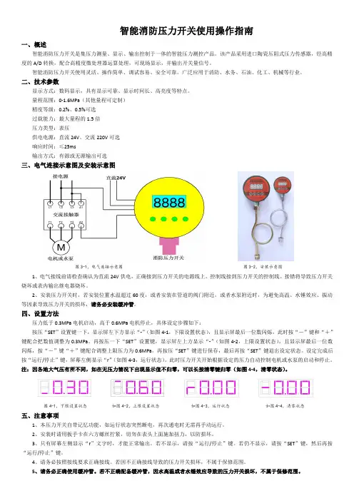
量程范围:0-1.6MPa (其他量程可定制)精度等级:0.2%、0.5%可选过载能力:最大量程的1.5倍压力类型:表压供电电源:直流24V 、交流220V 可选响应时间:≤25ms输出方式:有源或无源输出可选三、电气连接示意图及安装示意图图3-1,电气连接示意图图3-2,安装示意图1、电气接线前请检查确认为直流24V 供电,正确接到压力开关的电源线上。
控制线接到压力开关的控制线。
接错将导致压力开关烧坏或表内输出继电器烧坏。
2、安装压力开关时,若安装位置水温超过60度,或者安装在管道的阀门附近,或者水泵附近时,为避免高温、水锤效应、振动等因素导致压力开关的损坏,请务必安装缓冲管。
四、设置方法压力低于0.3MPa 电机启动,高于0.6MPa 电机停止,具体设定步骤如下:按压“SET ”设置键一下,显示屏左下方显示“-”(如图4-1,下限设置状态),且显示屏最后一位数闪烁,此时按“-”键和“+”键配合把数值调整为0.3MPa 。
再按压一下“SET ”设置键,显示屏左上方显示“-”(如图4-2,上限设置状态),且显示屏最后一位数闪烁,按“-”键“+”键配合调整上限压力为0.6MPa ,再按压“SET ”键进行保存,最后再按“SET ”键退出设定状态。
设定完成后按“运行/停止”键,屏幕左侧显示“r ”(如图4-3,运行状态)。
此时压力开关开始根据设定的压力自动控制电机或水泵的启动和停止。
注:因各地大气压有所不同,如在无压力情况下出现显示值不归零,可以长按清零键归零(如图4-4,清零状态)。
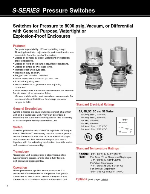
14Features:• Set point repeatability, +1% of operating range.• All wiring terminals, adjustments and visual scales are accessible from the front of the switch.• Choice of general purpose, watertight or explosion-proof enclosures.• Choice of fixed or full-range adjustable deadband.• Choice of single or two-stage units.• Manual reset units available.• Mounts in any position.• Rugged and vibration resistant.• Visual adjustment scales in psi and bars.• External adjusting nuts.• Separate electrical, pressure and adjusting chambers.• Wide selection of transducer wetted materials suitable for air, water, oil or corrosive fluids.• Mix and match switch and transducer components for increased stock flexibility or to change pressure ranges in field.General Description:ASCO S-Series pressure switches consist of a switch unit and a transducer unit.They can be orderedseparately for customer stocking and/or field assembly or as a complete factory-assembled unit.SwitchS-Series pressure switch units incorporate the unique ASCO TRI-POINT alternating fulcrum balance plate to control the operation of one or more electrical snap-action swtiches.The electrical snap-action switchtogether with the adjusting mechanism is a fully-tested,self-contained subassembly.TransducerT ransducer unit incorporates a diaphragm/piston type pressure sensor, and is also a fully-tested, self-contained subassembly.OperationWhen pressure is applied to the transducer it is converted into movement of the piston.This pistonmovement is then used to control the operation of the electrical snap-action switch in the switch unit.Standard Electrical RatingsSwitches for Pressure to 8000 psig, Vacuum, or Differential with General Purpose, Watertight or Explosion-Proof EnclosuresStandard Temperature RatingsOptions (See pages 34-35)EnclosuresASCO TRI-POINT S-Series switches are available in three standard enclosures.All of these enclosed units are made in accordance with NEMA and UL standards. General Purpose–Type 1.These enclosures are designed for indoor use to protect personnel from accidental contact with the equipment.S-Series general purpose switch units consist of a copper-free* aluminum die-cast body with a formed copper-free* aluminum cover;two 3/4”conduit hubs with one plug are provided.Watertight–T ype 4.Watertight and dust-tight enclo-sures are intended for use indoors and outdoors to protect the enclosed equipment against splashing or falling water, windblown dust and water, hose directed water, and severe external condensation.S-Series watertight switch units have a copper-free* aluminum die-cast body and a formed copper-free* aluminum cover with Buna “N”gaskets;two 3/4”conduit hubs with one plug are provided.Explosion-Proof–T ypes 7 and 9.T ype 7 enclosures are intended for use in locations defined by the National Electrical Code as Class I.T ype 9 enclosures are intended for Class II locations.Class I locations are those in which flammable gases are or may be present in the air in sufficient quantities to produce explosive or ignitable mixtures.Class I loca-tions are classified by group letter, which defines partic-ular atmospheres.Division 1 locations are areas where the hazardous concentration exists continuously, inter-mittently or periodically under normal operating condi-tions.Division 2 locations are those where the haz-ardous vapors are present only in case of accidental rupture or breakdown of equipment.ASCO TRI-POINT explosion-proof enclosures with letter B, C or D in the fifth position are listed for Class I, Groups B, C, and D, Division 1.They are also suitable for the less stringent Division 2 environment.Class II locations are those which are hazardous because of the presence of combustible dust.All ASCO TRI-POINT explosion-proof enclosures are listed for Groups E, F, and G locations.The switch body and cover are die-cast copper-free* aluminum with a Buna “N”gasket.T wo 3/4”conduit hubs with one plug are provided.Dimensions (inches)* Less than 0.6% copper.1516the maximumrange of the switch .1231718the maximum1934H-Series, P-Series and S-Series Snap-Action Switch OptionsOptional snap-action switches to meet specific electrical loads or application conditions are available on most ASCO TRI-POINT switch units. Generally, the construction of a switch unit with optional snap-action switches contains other specific parts and may be ordered only as a factory-built unit. To specify a particular optional construction, add the appropriate suffix to the switch unit action switch (suffix “P ”P-SeriesSwitch OptionsPanel Mount –Open frame P-Series compact switch units areavailable for panel mounting with the switch unit inside and the transducer outside. The panel separates the fluid sensing portion from the electromechanical portion. Five holes for bolts and operating stem must be drilled or punched through the panel.Three constructions are available: add the suffix listed below to the switch unit catalog number for the desired thickness.S-SeriesSwitch OptionsIndustrial Adjusting Nut Covers –Available in clear plastic or metal to prevent tampering with set point adjusting nuts.Clear plastic cover:To order, add suffix “1” to the switch unit catalog number, or order separately as SP01.Metal cover:To order, add suffix “2” to the switch unit catalog number, or order separately as SP02.JIC Construction –A switch unit having the electrical and adjusting nut covers attached to the switch body by a chain. Also designed to Type 13specifications. To order, add suffix “3”to the switch unit catalog number, or order separately as SP03.Terminal Block –Applicable to switch units with one single-poledouble-throw switch. The terminal strip is prewired to the snap-action switch. To order, add suffix “4” to the switch unit catalog number, or order separately as SP04.Factory Sealed –Explosion-proof units may be ordered with a factory seal separating the electrical chamber from the conduit hubs and 24” long #14 AWG 105°C. rated lead wires. To order, change the fourth digit of the “3”35Pressure Transducer OptionsP-Series and S-Series Temperature Transducer OptionsSpecial Wetted Materials –The following diaphragms maybe substituted on transducer body materials of aluminum,brass, polyester and stainless steel. To order, substitute the Oxygen Cleaning –Pressure transducers for oxygen serviceshould be specially cleaned. They are degreased and blacklight inspected, then assembled in a clean area and tested with oil-free air or nitrogen. Use metal body transducer with viton or neoprene diaphragm and add suffix “H ”Pressure Snubbers –A pressure snubber (1/4” NPTF by1/4” NPTM) installed in the transducer pressure connection will dampen the pressure spikes to a value which will not cause damage. It consists of a body with a porous metal disc of stainless steel through which the fluid passes. To order,select a snubber compatible with the fluid. Available by seperate catalog number only (see table below).Process Connection –A female process connection (1/4”NPT) is standard on all pressure transducers. A 1/2” NPT is available as an option on gauge pressure transducers. To order, add suffix “B ”Note: Armored Capillaries –Double braided copper armor isstandard for copper capillary units. Stainless steel spiral interlocked armor is available for stainless steel capillary units. Add suffix “C ” to transducer catalog number.Thermal Well –Use with direct or remote sensors forprotecting sensing bulb. This allows removal of bulb while maintaining a pressure-tight vessel. Available in 1/2” NPT or 3/4”NPT process connection in brass or 316 SS. Dimensions are in accordance with SAMA Std. RC17-9. Standard “U ” dimension (insertion length) is 2-1/2” for direct mount and 6’capillary units and is 4-1/2” for 12’capillary units.Longer Capillaries –Standard copper and stainless steelcapillary units can be furnished in 12’lengths. To order, add suffix “D ” to transducer catalog number. Consult ASCO for longer length capillaries.Union Connector –For use with remote units for mountingof bulb in fluid being controlled. Available in 1/2” NPT and 3/4” NPT process connections in brass or 316 SS.Thermal WellJam nuts provided with thermal wells.11Switch Unit – ASCO uses the term “switch unit ” to describe the electromechanical portion of a pressure or temperature switch. This is used in conjunction with a transducer unit to form a complete pressure or temperature switch.Transducer Unit – ASCO uses the term “transducer unit ” to describe that portion of a pressure or temperature switch to which a pressure or temperature is applied which converts the input signal to another form of energy to operate the switch unit.Two-Stage (Dual)– ASCO uses the term “two stage ” todescribe a pressure or temperature switch which is equivalent to two pressure or temperature switches which are independently adjustable. This switch is equivalent to two fixed deadband switches.Deadbands – The deadband is the difference between the set point and reset point readings. Deadbands are listed in the specification tables at nominal values. They are representative of the deadbands of the units at the middle of the range.The deadband values for the full range adjustable deadband switches and limited adjustable deadband switches indicate the values through which the deadband may be adjusted.Generally, as the set point is adjusted through the operating range, the deadband will vary. Normally, it will becomenarrower as the set point is towards the bottom of the range,and will become wider when the set point is towards the top of the range. The graph shown below indicates representative trends of this type of deadband variation.Temperature switch deadbands are a result of the characteris-tics of the vapor pressure curve as well as other factors.Normally, this results in a deadband which is narrower in the top third of the range than in the bottom third of the range.The values published are nominal and representative of mid-range set points.36Accuracy – The maximum deviation from the set point under specified operating condition (ambient temperature,barometric pressure, etc.).Adjustable Deadband – Refers to the capability of apressure or temperature switch to allow the deadband to be adjusted over a given range. Certain ASCO TRI-POINT switches have an adjustable deadband which can be adjusted over the total operating range of the switch.Adjustable Operating Range – The pressure or tempera-ture range of the switch within which the set point may be adjusted.Differential Pressure – The difference between twopressures. A differential pressure switch senses two pressure sources and can be adjusted to actuate on a desired difference between them.Guage Pressure – The actual reading of a typical pressure guage and is the difference between the pressure within a vessel and the atmospheric pressure surrounding it. It is normally measured in pounds per square inch (psig).Manual Reset – The switch is a semi-automatic device which operates automatically with a signal change in one direction but must be manually reset once the signal returns to its original position.Proof Pressure – A pressure which a device can besubjected to for extended periods of time without changes in its operating characteristics.Rated Overrange Temperature – A temperature which a device can be subjected to for extended periods of time without changes in its operating characteristics.Repeatability – The closeness of agreement among a number of consecutive measurements of the output for the same value of input under the same operating conditions approaching from the same direction. Repeatability isnormally specified as a percentage of the upper limit of the operating range.Example: Operating range 5-100 psig with +1%repeatability; equals +1% of 100 psig or +1 psig.Reset Point – After a pressure or temperature switch has reached its set point and operated the electrical switch, it must return to a point called the reset point before the electrical switch can return to its original position.Set Point – The pressure reading at which the electrical switch element changes contact position (it can be specified either increasing or decreasing).DefinitionsDeadbands1.5 x Catalog Value Catalog Value Half Catalog ValueBottom Mid TopPosition of Set Point in Range37These recommendations are to be used as a guide only, as service life of material is dependent on temperature, concentrations, or catalysts that may be added and other conditions which are beyond our control.Consult ASCO for specific service applications.Note:Items in black circles are standard catalog units.All others available on factory order.P - Indicates preferred construction. S - Indicates satisfactory construction.Transducer Material Code of Two Digits represents process connection material and diaphragm material, respectively; these are the sixth and seventh positions of the pressure transducer catalog number.Process Connection: 6th Position Diaphragm: 7th Position 1 Aluminum 4 316 S.S. 1 Buna “N ” 4 316 S.S.2 Brass 7 Nylon/Brass2 Viton6 Ethylene Propylene 3 303 S.S.3 Neoprene7 FluorosiliconeFluid Compatibility GuideFor high purity applications use stainless steel transducers.Notes:1Oxygen service requires special cleaning, specify suffix “H ”.2For steam service a condensate loop (pigtail) is required.3For pressure transducers for combustion service see pages 20-23.4Material availability refers to standard gauge pressure constructions only.5。
目录1 说明§1.1 重要说明§1.2 开关标识2 探测头安装§2.1 压力与真空探测头§2.2 差压探测头§2.3 温度探测头3 封装外壳的安装§3.1 “C”型外壳§3.2 “Z”型外壳§3.3 “V”型和“W”型外壳§3.4 “M”型外壳4 电气安装5 设定点调节6欧共体标准符合说明1 说明§1.1 重要说明* BETA压力开关属于精密仪器请正确放置或搬动。
BETA压力开关在达到设定点的(差压)压力或者温度时开关动作。
* 在按照说明书指示正确安装,该开关的设计与结构是完全免维护的。
切莫采用液态油或油脂润滑开关的任何部件。
* 除了更换外壳密封与安装支架外,不要移动或更换本开关的任何部件。
* 避免暴露在超高温、超低温、有侵蚀性环境中,-30~80℃为适宜温度。
* 调节螺丝有自锁性,所以在调节设定点后禁止封死调节螺丝。
* 安装前请详细检查铭牌上数据。
* 所有尺寸均以mm毫米标注。
* 如果您需要帮助请与供应商联系,开关只有在去污清洗后才能进行维护检修。
* 如果您需要额外的膜片O形圈和微动开关,请给出序列号向供应商购买。
* 开关的检修维护请由专业的仪表工程师实施。
除了更换膜片O形圈和微动开关以外,其它形式的检修维护有厂方执行。
* 非厂方检修维护的操作会影响产品本身的质量保证。
* 本章节的指导说明书的步骤也是安装步骤说明。
* 地基与工程环境的强烈振动可能会影响开关的正常功能。
§1.2 开关标识压力开关的铭牌上面标明了规格型号,4到7步可以确定该压力开关的设计组成,后缀的X+数字来表明特殊要求,该特殊要求可参照数据书。
外壳封装C1-P304L-S1N-B1-K1-Y-X2第一个字符即第一步标明了外壳封装形式:C、V、W、Z或M,参照图1-4和15。
探测头C1-P304L-S1N-B1-K1-Y-X2第一个和最后一个字符构成第二步标明了探测头规格及功能,参照图5-12和表1。
压力开关说明书产品作用:压力开关用于测量流经管道的液体(水及氟化处理的制冷剂)或空气的压力状态,其典型应用是显示压力与控制压力。
•机械寿命》10万次(参考值JC系列》40万次)•设定值调整:当设定值精度要求不高时,可根据控制器标度尺和系统中的压力表进行调试,当设定值要求较高时,请用专用压力校验仪和精密压力表进行调试。
压力开关内部安装有一个高灵敏度的单刀双掷接近开关。
开关可设定二个切换值,通常称为上限切换值和下限切换值。
具体调试方法:1. 压力开关顶部的右侧调节螺丝是直接调节上限切换值;2. 压力开关顶部的左侧调节螺丝是调节开关压差;3. 它们的关系是:上限切换值-开关压差=下限切换值即:上限切换值可以直接在标尺上调节下限切换值要通过1〜3操作来调节* 例如:(高压保护器的用法)要求被控介质的压力保持在0.5〜0.8Mpa 之间。
1. 选用设定值范围在0.1〜1.0Mpa 的压力控制器(JC-21 0,HNS-21 0 )2. 旋动顶部右边的压力调节螺丝,使指针指示在标度尺的0.8Mpa (8kg或8bar)处,此值为上限切换值。
3. 旋动顶部左边的压力调节螺丝,使指针指示在标度尺的0.3Mpa,下限切换值=上限切换值-开关压差=0.8-0.3=0.5 ,此值为下限切换值。
4. 将控制器的接线端子接入被控的电气回路。
请注意:①为公共接线。
③为常开端输出。
⑤为常闭端输出。
高压保护,请连接① ⑤,在正常升压时,①-⑤接通(①-③不通)。
压力升到设定上限时即0.8Mpa处,① -⑤不通(①-③接通)。
压力下降时,此时①-③接通,压力下降到下限设定点即0.3Mpa处时。
又切换为①- ⑤接通(①-③不通)。
降压停止,压力回升,则自动循环。
5. 接通电源,让被控介质(水、气)压力上升。
请注意观察调正,使压力开关的设定值与压力表指示一致,(如压力升至上限设定时,开关尚未动作,即旋动压力调节螺丝,微调到切换动作,并再次重复验证一次)并作下限验证,过程同上。
压力开关规格书(一)压力开关规格书是一种文档,其中包含压力开关的特性、性能和规格的详细说明。
这份规格书通常由生产商为了向用户提供规范指导而编写。
在该文档中,金属行业、塑料制品行业、压缩空气行业等生产压力开关的行业都有相关的规格书。
下面将对压力开关规格书进行详细说明。
一、压力开关的基本定义压力开关是一种控制装置,能够检测载荷、流量、液位、压力等物理量中的一个或多个,并把信号转换为开关量输出。
压力开关广泛应用于各种工业流程中,被称为“工业大脑”。
二、压力开关规格书的组成1. 压力开关名称和描述。
这通常包括该开关的品牌、型号、描述、颜色和特殊标志等信息。
2. 压力开关的性能。
这包括开关的操作范围、传感器类型和信号输出等,并对每个参数进行详细说明。
3. 压力开关的物理规格。
这包括尺寸、外形、材料、连接方式和重量等,并对每个参数进行详细说明。
4. 压力开关的环境条件。
这包括开关操作和存储的环境条件,包括温度、湿度、振动、冲击和防护等,并对每个参数进行详细说明。
5. 压力开关的安装和维护。
这包括将开关安装到应用设备上所需的步骤以及保养与维护,还要提供相应的图片和维护指导。
6. 压力开关的技术支持。
开关生产商通常会提供技术支持服务,例如培训、现场调整和应用工程师的支持等。
三、压力开关规格书的使用场景工业流程控制是压力开关主要的使用场景。
压力开关可以帮助生产制造商在各种流程控制应用中保证高效和可靠的操作。
下面是一些典型的应用场景:1. 压缩空气系统使用压力开关来控制空气压力。
2. 自动喷水灭火系统使用压力开关来感应水压并控制水流量。
3. 蒸汽锅炉使用压力开关来监测锅炉的蒸汽压力,并通过开关控制燃烧器的燃气流量。
4. 汽车发动机同样使用压力开关来监测发动机的空气流量和温度,以帮助发动机顺畅运转。
总体来看,压力开关规格书是一个非常有用的文档,可以帮助用户了解压力开关的特性、性能和规格,进而正确合理地使用它们。
因此,对于那些需要使用如此设备的人来说,他们应该了解什么是压力开关规格书,以及如何使用它们来达到自己的需求。
221 Code Process R ange & Temp.(6) Vac 0-600 1000 2000- Material Limits in.H 2O psi psi 3000 °F psi B-Buna N 0 to 150 ● ● ● ● V-Viton 20 to 300 ● ● ● T-Teflon 0 to 150 ● ● ● ● S-SS (5)(10) 0 to 300 ● ● P -Monel (5)(10) 0 to 300 ● ● NOTES: 1. Standard switch. 2. D ual switches are 2 SPDT snap-action switches not independently adjustable. 3. Estimated dc rating, 2.5A, 28 Vdc (not UL listed). 4. Estimated dc rating, .4A, 120 Vdc (not UL listed). 5. Available on pressure only. 6. A mbient operating temperature limits –20 to 150°F , all styles. Setpoint shift of ±1% of range per 50°F is normal. Switch calibrated at 70°F reference. 7. Items are wetted by process fluid. 8. Refer to Option Table. 9. O rder Option XUD, stainless steel process connection.10. On differential switches, stainless steel is available in 15, 30, 60 and 90 psid ranges only. Includes Teflon O-ring and 316 SS connection. TO ORDER THIS B-SERIES PRESSURE SWITCH:Pressure and Differential Pressure Switches, Watertight Enclosure, Type 400, B-Series • C hoice of actuators, including designs for fire-safe and NACE applications (8)• Readily available • Standard pressure connection materials: Pressure psi ranges - 316L stainless steel Differential psid ranges- Nickel-plated brass (9) of water ranges - Epoxy coated carbon steel B4 - P ressure switch, type 400, watertightenclosure meets NEMA 3, 4, 4X and 13, IP66 requirementsD4 - D ifferential pressure switch, type 400,watertight enclosure meets NEMA 3, 4, 4X and 13, IP66 requirementsThis general purpose Ashcroft ® switch series is ideal for use in virtually all Industrial and OEM applications.• Watertight NEMA 4X enclosure, IP66• Choice of switch elements for all applications, including hermeti-cally sealed• Wide choice of wetted materials, including all-welded Monel or stainless steel• Fixed or limited adjustable deadband• Approved for UL, CSA and FM (8) ratings • Setpoints adjustable from 15-100% of range4 - OPTIONS (See pages 238-239)5 - STANDARD PRESSURE RANGES (See page 235) 3 - ACTUATOR SEAL (7) Order D escription/Maximum Electrical Ratings Code UL/CSA Listed SPDT 20(4) Narrow deadband 15A, 125/250 Vac 21(9) Ammonia service 5A, 125/250 VacHermetically sealed22(3) switch, narrow 5A, 125/250 Vac deadband 23 Heavy duty ac 20A,125/250 Vac15A,125/250/480 Vac 24(1)General purpose 1/2A, 125 Vdc 1/4A, 250 Vdc 25 Heavy duty dc 10A,125/ Vac or dc 1/8HP 125/ Vac or dc 26(4)Sealed environment 15A, 125/250 Vac proof 27 High temp. 300°F 15A, 125/250 Vac 28Manual reset trip 15A, 125/250 Vac on increasing 29 Manual reset trip 15A, 125/250 Vac on decreasing 31 Low level (gold) 1A,125/250 Vac contactsHermetically sealed32 switch, general 11A, 125/250 Vac purpose 5A, 30 Vdc50 Variable deadband 15A,125/250 Vac UL/CSA Listed Dual SPDT (2)We recommend hermetically sealed switch elements for improved reliability. The hermetically sealed switch provides uncompromising contact protection in harsh or corrosive environments. The Ashcroft 400 Series is also approved for installation in Division II hazardous areas when supplied with hermetically sealed contacts.L-recognized component, LOOK FOR THIS AGENCY MARK ON OUR PRODUCTS。
智能压力开关操作手册一、特点●4位数字显示当前压力值。
● 2路开关量输出,带载能力1.2A●模拟量输出(4~20mA)●开关量可在零点到满度之间任意设定●外壳设有节点动作发光二级管,便于观察●按键调校及现场设置各种参数,操作方便●压力预设开关点和延滞切换输出二、概述智能压力开关是集压力测量,显示,输出、控制于一体的智能数显压力测控产品。
该产品为全电子结构,前端采用带隔离膜充油压阻式压力传感器,输出信号由高精度,低温漂的放大器放大处理,送入高精度的A/D转换器,转换成微处理器可以处理的数字信号,经过运算处理的信号控制两路开关,对控制系统压力进行测控。
该智能数字压力开关使用灵活,操作简单,调试容易,安全可靠。
广泛应用于水电,自来水,石油,化工,机械,液压等行业,对流体介质的压力进行测量显示和控制三、技术参数四、4.1机械连接:可以通过压力管接头(DIN3582外螺纹G1/4)(其他尺寸接头可在订货时说明),直接装在液压管路上。
在关键应用场合(如剧烈震动或冲击),压力管接头可以通过微型软管进行机械解耦。
4.2电气连接:1红:电源+ 2黄:电源-3 蓝:开关14 绿:开关25灰:4~20Ma为了防止电磁干扰的影响应注意以下事项:●线路连接尽量短●采用屏蔽线●尽量避免直接接近引起干扰的用户装置或电器和电子装置的接线●若用微型软管安装,壳体必须单独接地五、外形尺寸六、设置功能6.1开关量输出有两路开关量输出。
每路开关量输出可以设定1个压力开关点和一个开启延时值。
相应的输出会在开关点的吸合值到达时切换并在压力下降到低于释放值时回复。
6.2模拟输出根据型号规格:两路开关量+一路模拟量,带一路模拟输出。
可输出4~20mA6.3设置开关点(代号:)AL1H此值为开关1吸合值(压力到达此点时吸合,指示灯亮)。
AL1F此值为开关1释放值(压力到达此点时断开,指示灯灭)AL1D此值为开关1动作延时(切换前必须等待的时间秒数)AL2H此值为开关2吸合值(压力到达此点时吸合,指示灯亮)AL2F此值为开关2释放值(压力到达此点时断开,指示灯灭)AL2D此值为开关2动作延时(切换前必须等待的时间秒数)注:开关点由吸合值和释放值组态决定,吸合值大于释放值时为上限报警输出(常开功能),吸合值小于释放值时为下限报警输出(常闭功能)吸合值与释放值的差值为开关点的回差。
概述本说明书是关于SOR 压力开关在安装、过程联接、 电气联接和调校方面的说明,此种形式压力开关不 推荐用于存在高冲击压且高频率循环的高液压工作 场合。
注意:如果您发现某台开关有损坏,请尽快与工厂 或SOR 产品当地服务代表联系,以获得返修登记号 码,如果该产品无法返回工厂维修,应由授权的产 品服务代表提供现场服务,请与工厂或SOR 公司当 地服务代表联系技术支持事宜。
设计与规范的改动请恕不另行通知。
电气联接警告:在危险环境下开启防爆型开关,在盖移动前一定要保证电源已被断开,否则会导致严重的个人伤害和巨大的工厂损毁。
在开关壳内防置过多的导线或不当的联接可能会防碍开关正常的工作。
外壳型式 电气接口 接点 接线标志无螺丝端子 贴于绝缘纸上 导线颜色区别、标识 所有其它型式3/4NPT(F) 或 M20X 1.5(F) 特殊指定除外螺丝端子 贴于绝缘纸上 导线 颜色区别、标识 端子条块贴于绝缘纸上第1页/ 2页 ISO 9001质量体系认证真空开关(接线图解)当设定点为真空时,参照图一 当设定点为正压时,参照图二图一图二兰(公用) 黑(常开) 红(常闭) 绿(地线)兰(公用) 黑(常开) 红(常闭) 黄(公用2) 棕(常开2) 桔红(常闭2) 绿(地线)导线颜色标识压力开关 使用说明书安装1.用两个适当长度的1/4英寸螺栓,牢固地将开关外壳通过安装孔与仪表架或安装柱装配在一起。
2.不推荐通压力接口或电气接口的在线安装。
3.建议安装位置为电气接口竖直向下,以避免收集冷凝液,尽管如此,开关仍可全位置安装。
保证导线的电气性能符合所有应用的国家和场合,并且根据相关国家和场合的安全要求安装产品。
过程联接采用两个扳手安全地将引压管与压力接口联接:一个扳手夹住六角形压力接口,另一个扳手旋紧引压管或管接头。
重要:小心勿使压力接口松,压力接头从壳体上脱落。
警告:将外壳安装平板表面可能会导致外壳受到扭力,从而使压力开关不能正常工作。
压力开关说明书
产品作用:
压力开关用于测量流经管道的液体(水及氟化处理的制冷剂)或空气的压力状态,其典型应用是显示压力与控制压力。
●机械寿命≥10万次(参考值JC系列≥40万次)
●设定值调整:当设定值精度要求不高时,可根据控制器标度尺和系统中的压力表进行调试,当设定值要求较高时,请用专用压力校验仪和精密压力表进行调试。
压力开关内部安装有一个高灵敏度的单刀双掷接近开关。
开关可设定二个切换值,通常称为上限切换值和下限切换值。
具体调试方法:
1. 压力开关顶部的右侧调节螺丝是直接调节上限切换值;
2. 压力开关顶部的左侧调节螺丝是调节开关压差;
3. 它们的关系是:上限切换值-开关压差=下限切换值
即:上限切换值可以直接在标尺上调节下限切换值要通过1~3操作来调节
*例如:(高压保护器的用法)
要求被控介质的压力保持在0.5~0.8Mpa之间。
1. 选用设定值范围在0.1~1.0Mpa的压力控制器(JC-210,HNS-210)
2. 旋动顶部右边的压力调节螺丝,使指针指示在标度尺的0.8Mpa(8kg或8bar)处,此值为上限切换值。
3. 旋动顶部左边的压力调节螺丝,使指针指示在标度尺的0.3Mpa,
下限切换值=上限切换值-开关压差=0.8-0.3=0.5,此值为下限切换值。
4. 将控制器的接线端子接入被控的电气回路。
请注意:①为公共接线。
③为常开端输出。
⑤为常闭端输出。
高压保护,请连接①⑤,在正常升压时,①-⑤接通(①-③不通)。
压力升到设定上限时即0.8Mpa处,①-⑤不通(①-③接通)。
压力下降时,此时①-③接通,压力下降到下限设定点即0.3Mpa处时。
又切换为①-
⑤接通(①-③不通)。
降压停止,压力回升,则自动循环。
5. 接通电源,让被控介质(水、气)压力上升。
请注意观察调正,使压力开关的设定值与压力表指示一致,(如压力升至上限设定时,开关尚未动作,即旋动压力调节螺丝,微调到切换动作,并再次重复验证一次)并作下限验证,过程同上。
(反复验证几次)用红漆固定压力开关铁壳顶部的压力调节螺丝和压差调节螺丝。
*例如:(低压保护器的用法)
用户的正常水压为0.25Mpa要求当水压低于0.1Mpa,压力开关要关闭水泵。
1. 选用JC-203或HNS-203。
(也可选用JC-206或NHS-206)。
即控制值0~3kg范围。
2. 旋动顶部右边的压力调节螺丝,使指针指示在标度尺的0.15Mpa处,此值为上限切换值。
3. 旋动顶部左边的压力调节螺丝,使指针指示在标度尺的0.05Mpa,
下限切换值=上限切换值-开关压差=0.15-0.05=0.1,此值为下限切换值。
4. 控制水泵运转的电气线路:①接电源输入。
③接电源输出~水泵。
(>0.15Mpa通,<0.1Mpa断)
5. 接通电源时先打开管路水源,当水源压力大于0.15Mpa时,水泵开始工作,当压力下降时到0.1Mpa时,压力开关下限切换。
,水泵即会停止工作,以达到保护的目的。
产品安装:
1.注意:压力设定值(上限),必须大于压差设定值(压力设定值—压差设定值=下限启动值)例如:上限
设8公斤,压差设2公斤。
则8公斤关机。
压力下降到6公斤时启动。
如遇上不开启、不启动时,除了检查设定值是否有变化,还要检查接线是否连接牢固、电源有无变化。
压力表是否误差等多方面检查与判断来排除故障。
2.设定值的标准误差为:±0.5公斤/cm2 而且虽然可以依照压力控制器的窗口里的标尺来设定值,但调试中
是以压力表数据为标准参照。
3. 把压力控制器安装在水源管路中,注意压力控制器接头规格为7/16"-20UNF外螺纹。
用户可选用转换接头。
以保证内外丝接头互相合适。
(我处有2分、3分、4分NPT管螺纹外丝。
M10×1、M12×1、M12×1.25、M20×1.5公制外丝和2分NPT内丝供选配)
触点形式与产品接口示意图:
转换接头示意图:
1:公共接点
1-3:压力上升时关闭
1-5:压力下降时关闭
箭头表示压力增大时的动作方向
●注意事项:
1. 被控介质应对黄铜、锡青铜及铅锡焊料无腐蚀作用。
2. 打开控制器盖安装时,请勿旋动内部的螺丝或拨动内部零件(除接线螺丝外)。
3. 被控介质的压力请勿超过表中规定的最大允许压力。
4. 控制器出厂起保用12个月,凡属产品质量问题,本公司负责及时维修或更换。