机械式压力开关使用说明书
- 格式:doc
- 大小:62.50 KB
- 文档页数:2
双簧机械压力开关调节说明书双簧机械压力开关是一种常用的压力控制装置。
其作用是监测压力,当压力达到一定设定值时,开启或关闭电路。
这种开关特别适用于工业、农业和家庭设备中,需要对压力进行监测和控制的场合。
本文将详细介绍双簧机械压力开关的调节方法。
1. 调节压力范围首先,我们需要设计和调整双簧机械压力开关的压力范围。
压力范围的选择取决于所监测的对象的性质和压力大小。
假设我们要监测某个压缩空气罐内的压力,首先要知道该罐的压力最高可以达到多少,然后设置开关的开关量。
这里需要注意的是,双簧机械压力开关的压力范围是可调的。
我们可以通过旋转调节螺母调整最小压力值,并通过旋转调整螺柱调整最高压力值。
2. 调节压力差除了压力范围,我们还需要调节压力差。
压力差是指在压力测量过程中,开关的下限压力和上限压力之间的差值。
这种差异通常可调,以保证开关闭合的准确性。
要调节此参数,我们可以使用压力表来测量压力,并通过旋转调整螺柱或螺母来调整压力差值。
3. 连接电路调整好的双簧机械压力开关需要连接电路,以便于监控和控制压力。
我们可以根据设备的工作需求来设计电路。
电路的安装需要注意的是,在使用中请避免过度施加力量,以免机械部件损坏。
4. 维护和保养在使用中,双簧机械压力开关需要定期进行维护和保养。
首先,要确保机械部件清洁和润滑,以保证其正常运转。
其次,需要检查电路的连接情况和电路电源的稳定性,以确保其正常工作。
如果发现机械故障,请立即维修或更换。
综上所述,双簧机械压力开关是一种可靠的压力控制装置。
正确地调整其参数不仅能确保设备的稳定运行,还能延长其使用寿命。
使用过程中,我们需要定期进行检查和维护,以保证其正常工作。
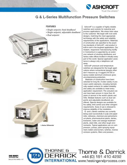
FEATURES• Single setpoint, fixed deadband• Single setpoint, adjustable deadband • Dual setpointAshcroft ®is a supplier of highly reliable switches and controls for industrial and process applications. We stress total value to the customer. We begin with rock-solid designs, matching the most appropriate technology with the safety and reliability requirements of the applications. Materials of construction are specified to the exact-ing standards of Ashcroft ®, and product is built to last in the toughest applications. Our modern, responsive manufacturing facility in Connecticut is supported by an exten-sive network of stocking distributors and factory sales offices located in v irtually every part of the world. Special application assis-tance is always only a telephone call away.Ashcroft ®pressure and temperatureswitches are designed for the tough appli-cations where conventional designs often don’t measure up. A rugged 316 SS or epoxy-coated aluminum enclosure gives uncompromising protection.Materials of construction have been selected for long life. A wide variety of pre-cision switch elements, including hermeti-cally sealed contacts for added reliability and safety are available to meet every application requirement. The actuators we use have been proven in more than 40years of service in the world’s plants and mills. Multiple features such as dual set-points and adjustable deadbands are offered. Special designs are available for fire safety, limit control and other stringent requirements. Ease of use is stressed to improve reliability of the installation.G- and L-Series switches are currently being used successfully in pulp and paper mills, refineries, chemical and petrochemi-cal plants, pharmaceutical plants, dairies,breweries, water and sewage treatment plants, steel mills, and other tough envi-ronments. Typical applications are on com-pressors, pumps, paint spraying equip-ment, boilers and burners, turbines, reverse osmosis systems, filters and presses.G-SeriesL-SeriesL-Series DifferentialNOTES:1. Switches may generally be set between 15% and 100% of nominal range on increasing or decreasing pressure.Consult factory for applications where setpoints must be lower.2. All deadbands are give The nominal range column.Deadbands shown are for switches with Buna N diaphragm. Approximate deadbands for optional diaphragms:Viton: Multiply Buna N value by 1.4Teflon: Multiply Buna N value by 1.2Stainless Steel: Multiply Buna N value by 1.7 Monel: Multiply Buna N value by 1.73. Deadbands for LPA, LDA, GPA, and GDA are adjustable between the values shown for all diaphragm materials.4. Deadbands for LPS, LPD, LDS, LDD, and GPS, GPD, GDS, GDD models are fixed within the range of values shown.5. Deadbands given are for zero static working pressure.6. Psid models cannot be used in vacuum applications.7. Proof pressure for stainless steel diaphragms is 4000 psi.G- and L-SERIES PRESSURE SWITCH AND DIFFERENTIAL PRESSURE SWITCH ORDERING INFORMATION1 – FUNCTIONGPS/LPS -Pressure control, single setpoint, fixeddeadband.GPA/LPA -Pressure control, single setpoint,adjustable deadband.GPD/LPD -Pressure control, two independentlyadjustable setpoints, fixed deadband.GDS/LDS -Differential pressure control, singlesetpoint, fixed deadband.GDA/LDA -Differential pressure control, singlesetpoint, adjustable deadband.GDD/LDD - Differential pressure control, two inde-pendently adjustable setpoints, fixed deadband.5 – PRESSURE CONNECTION (1)Order Code25 1⁄4NPT FemaleStandard on Pressure and D/P 06 1⁄4NPT Female and1⁄2NPT Male Combination Pressure Only 07 1⁄2NPT FemaleNOTES:1. These items are wetted by process fluid.2. Ambient operating temperature limits –20 to 150°F, all styles. Setpoint shift of ±1% of range per 50°F tempera-ture change is normal. Switches calibrated at 70°F refer-ence.3. Estimated dc rating, 2.5A, 28 Vdc (not UL listed).4. Estimated dc rating, 4A, 28 Vdc (not UL listed).5. Not UL listed at 480 Vac.6. Standard on G Series ˝H O ranges7. Supply static pressure for D/P switches.8. Stainless steel diaphragm only.9. Not available with Buna-N diaphragm.10. Available with GPS/LPS and GDS/LDS models.11. LDS, Buna N and Viton diaphragm only.12. LPS, stainless steel diaphragm only.13. All welded available on pressure models only.14. Order switch and 15-320SX-02T CG seal.15. Order switch and 20-320SX-02T CG seal.16. Not available for temperature ranges.17. Available on L-Series only.18. Not available with dual setpoints.7 – NOMINAL RANGESee page 3SWITCH ELEMENTS FOR FOR GPD/LPD,GPS/LPS, LDD/GDD & LDS/GDS CONTROLSCodeSingle DualSwitch elements UL/CSA listedK KK Narrow deadband 15A, 125/250 VacF FF Sealed environment 15A, 125/250 Vacproof15A, 125/250/480 Vac G GG General purpose 1/2A, 125 Vdc 1/4A, 250 Vdc Hermetically sealedP PP switch, narrow 5A, 125/250 Vac deadbandHermetically sealedJ JJ switch, general 11A,125/250 Vac purpose 5A, 30 Vdc W WW Ammonia service 15A, 125/250 Vac C CC Heavy duty ac 22A, 125/250 Vac S Heavy duty dc 10A, 125 Vac or dc⁄HP , 125 Vac or dc Y YY High temp. 300°F 15A, 125/250 Vac U UU Manual reset trip on 15A, 125/250 Vac increasingE EE Manual reset trip on 15A, 125/250 Vac decreasingHermetically sealedL LL switch, gold contacts 5A, 125/250 Vac M MM Low level, gold 1A, 125/250 Vac contacts2 – ENCLOSUREN4- NEMA 4, 4XL-Series: Epoxy Coated, Die Cast Aluminum, IP66G-Series: 316 SS IP656 – G-, L-SERIES PRESSURE SWITCH OPTIONSAvailable Differential Series Pressure Pressure Code Description G L psi ˝H O psid ˝H O XCH Chained Cover • • • • • • XFP Fungus Proof • • • • • • XFS Factory-Adjusted Setpoints • • • • • • XG5 Gas/OilUL Limit Control to 150 ˝H2O • •LDS only XG6 Gas/OilUL Limit Control to 600 psi • •LPS only XG8 Steam Limit Control to 300 psi • • XG9 Fire Safe Actuator • • High Operating Pressure for H2O Ranges:XHX 40 PSI Static (Pressure and D/P) • • • • 100 PSI Proof (Pressure) 160 PSI Proof (D/P)XJL ⁄˝ to ⁄˝ Reducing Bushing • • • • • • XK3 Terminal Blocks • • • • • • XNH Tagging Stainless Steel • • • • • • XPK Pilot Lights • • • • • XPM 3/4˝ Sealed Conduit Connectionwith 16˝ Lead Wires • • • • • • XTA 316SS Pressure Connectionfor ˝H2O Ranges • • • • XUD 316SS Pressure Connectionfor psid Ranges • • • X2C DPDT with Single SetpointAdjustment • • • • • • X6B Cleaned for Oxygen Service • • • • XFM FM Approval • • • • • X3A 1⁄˝ Sanitary Seal with Glycerin Fill • •2˝ Sanitary Seal with Glycerin Fill • •XHS High Static Operating Pressurefor PSI Range D/P • • • 4 – ACTUATOR SEAL (1)Process RangeCode Temp.(2) 2000- & Limits Vac 0-600 1000 3000 Material °F ˝H O psi psi psi B-Buna-N 0 to 150 • • • • V-Viton 20 to 300 • • • T-Teflon 0 to 150 • • • • S-St.St 0 to 300 • • P-Monel 0 to 300 •GP D N 4G G 25X K 330 PSIB1 2 3 4 5 6 7Additional options available, consult your Ashcroft representative.3 – SWITCH ELEMENTS FOR GPA/LPA,GDA/LDA CONTROLSDescription/Maximum Electrical Ratings Code UL/CSA listed 10A,125/250 Vac H General purpose 1/2A, 125 Vdc 1/4A, 250 Vdc Hermetically sealedJ switch, general 11A, 125/250 Vac purpose 5A, 30 VdcPressure Switch – psi RangesPressure Switch –Inches Of Water RangesDifferential Pressure Switch – Inches Of Water RangesDifferential Pressure Switch – psi Differential RangesHIGH PRESSURE PORTLOW PRESSURE PORTDimensions – G-SeriesPressure Switch – psi Ranges Pressure Switch –Inches Of Water RangesDifferential Pressure Switch –Inches Of Water Ranges Differential Pressure Switch –psi Differential Ranges4.126.091/4 NPT FEMALE4.12Dimensions – L-Series。
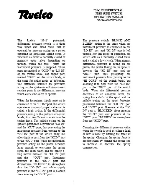
“SS-2 DIFFERENTIAL PRESSURE SWITCH OPERATION MANUAL OMP# 4202XDX000The pressure switch “BLOCK AND BLEED” action is the same when the instrument pressure is connected to the “LO IN” port and “HI IN” port is left unused. For this mode of operation, the switch acts as a normally closed valve and is called a low switch. When normal differential pressure is acting on the piston, the center O-ring on the spool is between the “HI IN” port and the “OUT” port thus preventing the instrument pressure from passing to the “HI PORT” of the switch body, but allowing it to flow from the “LO IN” port to the “OUT” port of the switch body. When the differential pressure decreases to an abnormal level, the spring force shifts to the spool and the middle o-ring on the spool becomes positioned between the “LO IN” port and “OUT” port. Pressure at the “LO IN” port is “BLOCKED” from entering the “OUT” port and pressure at the “OUT” port “BLEEDS” to atmosphere from the “HI IN” port. The Ruelco “SS-2” pneumaticdifferential pressure switch is a threeway block and bleed valve that isoperated by pressure acting on a pistonopposing an adjustable spring force. Itfunctions as either a normally closed ornormally open valve depending onthrough which the two ports theinstrument pressure is supplied. Theseports are marked as “HI IN” or “LO IN”on the switch body. The output port,marked “OUT” on the switch body, isthe same for either mode of operation.The difference between the pressuresacting on the upstream and downstreamsensing ports is the differential pressurewhich causes the valve to operate.When the instrument supply pressure isconnected to the “HI IN” port, the switchoperates as a normally open valve and iscalled a high switch. If the differentialpressure acting on the piston is at normallevels, it is insufficient to overcome thespring force. The middle o-ring on thespool is positioned between the “LO IN”and the “OUT” port, thus preventing theinstrument pressure from passing to the“LO IN” port of the switch body, butallowing it to pass from the “HI IN” portto the “OUT” port. When the differentialpressure acting on the piston becomeslarge enough to overcome the springforce, the spool shifts and the center o-ring moves between the “HI IN” portand the “OUT” port. Instrument pressure at the “OUT” port and downstream “BLEEDS” to atmosphere thru the “LO IN” port while supply pressure at the “HI IN” port is blocked from entering the “OUT” port.Changing the differential pressure value when the switch is used as either a high or low is done by altering the force of the spring. Changing the spring force is accomplished by turning the spring cap to increase or decrease the spring compression.2.0 INSTALLATION: 2. Small pliers.3. High quality silicone base lubricant.The “SS-2” differential can be panel mounted (with optional panel mount nut) or supported by piping from the sense port in either vertical or horizontal positions. If the switch is mounted horizontally, it is recommended that the small vent hole in the side of the switch body be oriented in a downward position. This will prevent any debris from accumulating in the spring cavity or above the sense piston. 4. An appropriate safety solvent. 3.1 PARTIAL DISASSEMBLY A) Spring Removal3.1.1)If the switch is installed in an operating instrument system, it is not necessary to remove any instrument supply or sense pressure. If the unit is a high switch, it will trip when changing the spring; if it is a low switch, then it will not. So precautions should be taken to avoid any unwanted reactions in the instrumentation system.Proper pipe thread sealant should be used on any pipe fittings threaded into the pressure switch ports. If stainless steel fittings are used, a sealant that will prevent galling is required. The supply gas flowing through the switch body should be filtered and free of large particles. If compressed air is used, it does not have to be lubricated. If natural gas is used as the instrument pressure, then it should contain as little condensate or crude oil as possible. This will extend the life of the seals. When the switch is mounted using the 1/4” NPT base connection and the instrument pressure ports are not in the desired position after the base connection is adequately tightened, DO NOT loosen the body from the base to re-position the ports. Instead, remove the switch and re-make the 1/4” NPT connection.3.1.2) To obtain access to the spring(Item 2), rotate the lock ring (Item 4) clockwise to loosen it from the spring cap (Item 1).3.1.3) Rotate the spring cap (Item 1)counterclockwise until it is disengaged from the switch body (Item 8).3.1.4) Remove the spring from itscavity in the switch body.3.0 DISASSEMBLY (See Spec Sheet)3.1.5) Follow the procedures in repairand assembly section (Steps 4.1.4 and 4.14) of this manual to re-install the spring.Tools and materials required for proper disassembly, repair and assembly are as follows: 1. 7/8” and 1” open end wrenchesor two crescent wrenches of adequate size.B)Piston Removal3.1.6)If the switch is panel mounted, itis not necessary to remove itfrom the panel. It will benecessary to disconnect anypiping or tubing from the basethat would prevent the base frombeing removed. When the switchis supported by the ¼” NPTconnection on its base (Item 12),disconnect any piping or tubingfrom the switch body that wouldprevent its removal from theswitch base. CAUTION: Be surethat all instrument or sensepressures are completely bled tozero before disconnecting anypiping or tubing.3.1.7)Use the appropriate wrenches tohold and loosen the base from theswitch body. Unthread the basecompletely from the switch body. 3.1.8)Unthread the lower housing(Item 18) from the baseassembly. Use appropriatewrench to loosen the hex nutItem 19) from the shaft-pistonassembly.3.1.9)Remove the installed cup seal(Item 16) from the piston (Item17).3.1.10)Procedure for re-installing thepiston cup seal and the shaft sealis in the repair and assemblyprocedure of this manual.3.2FULL DISASSEMBLYNOTE: Use the following instructions to completely disassemble the pilot for repair and cleaning. CAUTION: Be sure that all instrument or sense pressures are completely bled to zero before disconnecting any piping or tubing.3.2.1)Follow the procedures statedunder partial disassembly toremove the spring and piston.3.2.2)Remove the spool (Item 8) fromthe switch body. If it isnecessary, use the small pliersand grip the large end of thespool.3.2.3)The seals on the spool, (Item 8)may now be replaced as perinstructions given in the repairand assembly section of thismanual.4.0REPAIR AND ASSEMBLY(See product data sheet forreplacement part numbers).4.1)Remove the seals from the spooland piston.4.2)Clean all parts using anappropriate safety solvent.4.3)Inspect the spool for any majordamage such as burrs or nicks onits outside diameter. Also inspectit for straightness. Replace thespool (Item 10) if damaged.4.4)Examine the polished bores ofthe switch body (Item 8) andbase (Item 12) for gouges andrough surfaces. Be sure that allheavy dirt deposits have beenremoved. Replace any damagedpieces.4.13) Install the lock ring onto theswitch body and place the spring plate into the body cavity. NOTE : If the switch is panel mounted, install it into the panel and secure with a panel mounting ring prior to installing the lock ring (Item 4) and spring plate (ITEM 6). 4.5)Replacement seals from an authentic RUELCO REPAIR KIT is recommended to ensure proper switch performance. 4.6)Install new seals on the spool and lightly lubricate the seals and spool. CAUTION: Do not leave excessive lubricant on the spool. Doing so may prevent the switch from operating.4.14) Install the spring into the switchbody. CAUTION : Verify that the spring is the proper color for the range required as shown on the Range Selection Chart on the Specification Sheet $XXXX-12-95. 4.7)Verify the required switch range from the Range Selection Chart on the specification sheet 4XXX-12-95.4.8) Install the required cup seal (Item 16) on the large piston and the o-ring on the shaft (Item 20).4.15) Thread the spring cap onto theswitch body. Adjust the switch operation as per user requirements and methods.4.9)Lightly lubricate the piston seal and piston. DO NOT over lubricate or the switch performance may be adversely affected.4.10) Install the spool completely intothe switch body. Move it in and out of the body approximately ¼” to check that it moves freely.4.11) Install the shaft in to the pistonand tighten the hex nut. Install the shaft-piston assembly into the lower housing (Item 18) and grip the shaft on the shaft-piston assembly with the small pliers and move the piston back and forth in the base to verify that it moves freely. Thread the upper housing onto the lower housing.4.12) Thread the switch base into theswitch body and firmly tighten.5.0RECOMMENDED MAINTENANCEPROCEDURE MAINTENANCE5.1) Test Switch Trip Pressure Every 30 days5.2) Disassembly, inspect and lubricateYearlyorasrequired 5.3)Replaceallseals Every two years or as required 6.0TROUBLESHOOTINGPROBLEM1)Switch does notoperate when high orlow trip pressures areexceeded duringtesting or normaloperation.2)Gas or liquid leakingfrom small holebelow spring cap.3)Gas or liquid leakingfrom small holeabove switch base.4)Deadband and setpoint repeatabilityare larger than switchspecifications. PROBABLE CAUSEA)Switch adjustmenttampered with.B)Debris plugging sensorbody (Item 8) ports.C)Spring (Item 2)malfunction.D)Debris plugging thebase sense port or thepiston (Item 17).E)Spool seals (Item 7)and/or piston seal(Item 16) swollen.A)Damaged spool o-ring (Item 7).A)Damaged spool o-ring or guide sleeveseal (Item 9).A)Switch o-rings dry.B)Cause E for problem#1.RECOMMENDED ACTIONRe-adjust switch peroperating requirements.Disassemble switch as perprocedure in Section 3.0 andclean switch body. Cleaninstrument system filters.Remove the spring cap (Item1) and inspect spring (Item 2)for damage. Replace ifnecessary.Remove base and piston asper procedure in Section 3.0and clean. Begin cleaning ona regular basis.Disassemble as per procedurein Section 3.0 and 4.0. Trybetter filtration to keepcondensate out of supply gas.Disassemble and repair as perprocedures in Section 3.0 and4.0.Disassemble and repair as perprocedure in Section 3.0 and4.0Follow procedures in Section3.0 and4.0 to disassemblethe switch, lubricate all sealsand re-assemble.Same as problem #1.。

SWITCHGENIE 10 - SWITCHGENIE 12GENERALRead carefully the instructions before installing this unit. Verify the tech-nical characteristics of the motor in order to assure the compatibility with the device.DESCRIPTION (diagram A)SWITCHGENIE is an electronic pressure switch with integrated digital ma-nometer. It manages the start and stop of a single-phase pump up to 2.2kW (3 HP). Cut-in and cut-out pressures are easily adjustable through the users control panel.Wiring is analogous to the traditional electromechanical switch.It can operate as a differential pressure switch and as reverse pressure switch.Unit SWITCHGENIE 12 in addition to all the features of the basic SWITCH-GENIE includes instantaneous reading of current drawn. This patented system controls and manages the overcurrent, dry-run operation and fast-cycling.Unit SWITCHGENIE 12 in addition to all the features of individual assembly includes the option to be synchronized to another unit SWITCHGENIE 12 managing and protecting 2 pumps operating in cascade with alternated starting sequence.CLASSIFICATION AND TYPEAccording to IEC 60730-1 and EN 60730-1 this unit is a control sensor device, electronic, independent assembly, programming type A with action type 1B (microdisconnection). Operating value: I <20% I learned. Pollution degree 2 (clean environment). Rated impulse voltage: cat II / 2500V. Tem-peratures for ball test: enclousure (75) and PCB (125).OPERATING CHARACTERISTICS (diagram C)• Adjustable cut-in and cut-out pressures.• Integrated digital pressure gauge with bar and psi indication.• Inner pressure transmitter.• Dry-run protection:• Through minimum adjusted height for basic SWITCHGENIE.• Through the instantaneous current consumption in case of SWIT-CHGENIE 12.• Overcurrent protection (only SG12).• ART Function (Automatic Reset Test). When the device has stoppedthe pump by the intervention of the dry-running protection system, the ART tries, with scheduled basis, to re-start the pump in order to restore the water supply. See “ART. Automatic reset function“. Must be activated in the step 6 of the ADVANCED MENU (Ar1).• Fast cycling: when the hydropneumatic tank has lost too much air and, consequently, frequent start-stop cycles are produced this alarm isactivated and is delayed the start of the pump. Must be activated inthe step 2 of the BASIC MENU (rc1).• Manual start push-button (ENTER).• 3 operation modes: differential, reverse and synchronized (onlySG12).• Control panel with 3-digit display, LED indicator lights and push-buttons.• Volt-free contact for monitoring the alarms displayed in screen origi-nated by irregularities or problems of the system (only type SWITCH-GENIE 12A).• Available settings:• Stand-by mode.• Minimum period between fast cycles.• Start and stop delay.TECHNICAL CHARACTERISTICS• Rated motor power: 0,37-2,2 kW• Power supply: ~1 x 110-230 V• Pessure max. 0,8 MPa• Frequency: 50/60Hz• Max. current: 16 A• Protection degree: IP55• Max water Temperature: 50ºC• Max environment Temperature: 60ºC• Cut-in range (start pressure) 0,5÷7 bar• Cut-ot range (stop pressure) 1÷8 bar• Max. differential 7,5 bar• Minimum differential (adjustable) 0,5÷1,5 bar• Factory setting (start/stop) 3/4 bar• Hydraulic inlet G 1/4” Female• Net weight (without cables) 0,3 kg HYDRAULIC INSTALLATION (diagram A)SWITCHGENIE equipment must be threaded to a fi tting G1/4” male at the pump´s outlet.Before connecting the SWITCHGENIE verify that the hydraulic system is properly installed, especially if the hydropneumatic tank is pressurized. ELECTRIC CONNECTION (diagram B)The electric connection must be performed by qualifi ed personal in compliance with regulation of each country.Before doing manipulations inside the device, it must be disconnected from the electric supply.Wrong connection could spoil the electronic circuit.The manufacturer declines all responsability in damages caused by wrong connections.Check if power supply is between 115-230V.If you have purchased the unit without cables follow diagram B:• Use cables type H07RN-F 3G1 or 3G1,5 with section enough to thepower installed.• Do the pump connection U, V and .• Do the power supply connection L1, N and .• The earth conductor must be longer than the others. It will be the fi rst one to be mounted during the assembly and the last one to be dis-connected during the dismantling. T he earth conductors connec-tions are compulsory!CONTROL PANEL (diagram C)The meanings of the different control panel elements are summarized on the following tables, where:• O means lit LED light.• ( ( O ) ) means slow-fl ashing.• (((O))) means fast-flashing.STARTUP (diagram C)Before starting the device please read the previous sections, espe-cially “Hydraulic Installation” and “Electrical connection”.Follow next steps:1. Start the device by pressing .2. Only for type SG12 set the pump rated current intensity value.- Press during 3 seconds.- The current intensity value is displayed on screen, LED A lights up and display is fl ashing.- By mean of and is adjusted the rated current refl ected in the characteristics plate of the motor. See Note 1.- Press for validation.3. Set the cut-in (start) pressure:- Press during 3 seconds.- The start pressure value is displayed on screen, LED START lights up and display is fl ashing.- By mean of and is adjusted the start pressure from 0,5 to 7 bar.- Press for validation.4. Set the cut-out (stop) pressure:- Press during 3 seconds.- The stop pressure value is displayed on screen, LED STOP lights up and display is fl ashing.- By mean of and is adjusted the stop pressure from 1 to 8 bar.- Press for validation.5. The unit is ready to operate but more optional adjustments can be set through basic and advanced MENUS. See the next chapter.Remark 1: it is important to introduce exactly the rated current specifi ed on the nameplate of the pump.BASIC MENU + (diagram C)- Press simultaneously + during 5 seconds.- By mean of or the values can be changed.- Press for validation.ADVANCED MENU + +- Press simultaneously + + during 5 seconds.- By mean of or the values can be changed.- Press for validation.Remark 2:Basic SWITCHGENIE can only detect dry-running operation through the minimum pressure. This means that plumber must determine the water column of the installation, the start pressu-re of the pump and place the minimum pressure below the start pressure.It can also occur that pumping system is running out of its curve so that the pump is unable to provide the minimum pressure because the fl ow requirement is excessive. In this case SWITCHGENIE would activate a false dry-running alarm.If these concepts are not clear, it is preferable not confi gure this protection or install the SWITCHGENIE 12 with accurate and easy setting of dry-run detection.SYNCHRONISATION (ONLY FOR SWITCHGENIE 12)SWITCHGENIE 12 can be synchronized to another unit SWITCHGENIE 1managing and protecting 2 pumps operating in cascade with alternated starting sequence. Next steps must be followed:1. SET identical cut-in and cut-out pressures in both units.2. GO TO ADVANCED MENU: + +- In step 2in the other unit (this one will be the slave).- In step 3: select identical parameters of differential d.XX.3. Press repeatedly until exit the ADVANCED MENU.4. Press in order to disable the units. Is displayed “OFF”.5. Press again in both units in order to activate the synchronization.Remark 3: after 10 cycles the unit confi gured E01 will display pressu-re and the unit confi gured E02 will display current in Amps.ACCURATE DRY-RUNNING DETECTION (diagram C)In the SWITCHGENIE 12 model it is enough to set the rated current of the pump in order to activate the overcurrent and dry-running protection. However, the accuracy of dry-running detection can be improved by the activation of DR1 parameter in the ADVANCED MENU. The following steps must be followed:1. Drain the hydraulic installation and verify that the hydropneumatic tank is infl ated to the required pressure.2. Go to the ADVANCED MENU:- Press simultaneously + + during 5 seconds.- Press 7 consecutive times to accept and go to the next step until reaching dr0.- Using , set dr1.3. Press and close all the valves.4. The pump will start, will fi ll the installation and will stop at the cut-out pressure.5. Now, SWITCHGENIE 12 knows the current consumption curve of the pump.If you install a new pump this process should be repeated.If you enter the CURRENT INTENSITY MENU by pressing for 3 seconds all this process is invalidated because is predominant the rated current manually introduced.PRESSURE SENSOR CALIBRATIONIn case of wrong lecture of the pressure sensor it can be adjusted again. For the pressure sensor calibration is necessary to have a pressure gauge in the installation. Proceed following next steps:ZERO REGULATION1. Open the taps living the hydraulic net without pressure.2. Press simultaneously the buttons and until the display show0.0 fl ashing.3. Press to validate.FULL SCALE1. Start the pump until cut-out of the pressure switch.2. Press simultaneously the buttons and till the display fl asheswith a fi gure.3. Adjust the pressure with the arrows push-buttons to get the pressuredesired.4. Press to validate.Remark 4: pressure sensor decalibration should not be a normal event. If it is frequently repeated contact the technical service. WARNINGS AND ALARMSEC STAMENT OF COMPLIANCECOELBO CONTROL SYSTEM, S.L.States, on our own responsibility, that all materials here with related com-ply with the following European Directives:- 2014/35/EU.- 2014/30/EU.- 2014/65/EU.Name: - (SWITCHMATIC)- (SWITCHMATIC 2)Standards : EN-60730-2-6, EN-60730-1, EN-61000-6-1, EN-61000-6-3, IEC-60730-1, IEC-60730-2-6INDIVIDUALGROUP (ONLY SG12)DIAGRAM C DIMENSIONS。
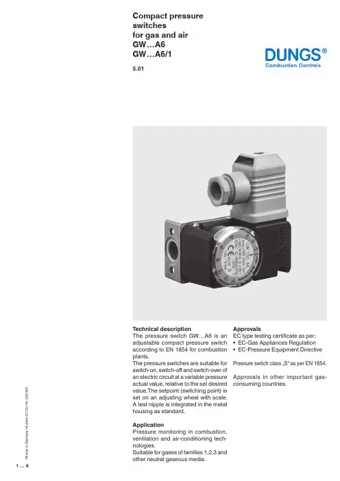
1 (6)Compact pressure switchesfor gas and air GW…A6GW…A6/15.01T echnical descriptionThe pressure switch GW…A6 is an adjustable compact pressure switch according to EN 1854 for combustion plants.The pressure switches are suitable for switch-on, switch-off and switch-over of an electric circuit at a variable pressure actual value, relative to the set desired value.The setpoint (switching point) is set on an adjusting wheel with scale. A test nipple is integrated in the metal housing as standard.ApplicationPressure monitoring in combustion, ventilation and air-conditioning tech -nologies.Suitable for gases of families 1,2,3 and other neutral gaseous media.ApprovalsEC type testing certificate as per: • EC-Gas Appliances Regulation • EC-Pressure Equipment Directive Pressure switch class …S“ as per EN 1854.Approvals in other important gas-consuming countries.P r i n t e d i n G e r m a n y • E d i t i o n 07.20 • N r . 229 544Functional descriptionSingle-acting pressure switch in over-pressure range.The pressure switches operate without any power supply.Switching responseGW…A6Short response time during pressure fluctuations.GW…A6/1Slow response time during short-term pressure fluctuations by additional damping nozzle.GW…A6 pressure switchThe control unit responds to pressure. If the setpoint is exceeded or undershot, the circuit is switched on, off or over.GW… / …A6 double pressure switchCombination of two flanged GW... A6 single pressure switches. The two setpoints are set separately and inde-pendently. A combination of different setpoint ranges is therefore possible. The two control units are fed from the same medium at the medium’s pres-sure.p↓ [mbar]p ↓ [mbar]2 (6)SpecificationsMax. operating pressure Pressure connectionMeasuring connection T emperature rangeMaterialsSwitching voltage Nominal current Switching currentElectrical connectionDegree of protection Setting toleranceDeviation GW 3 A6 - GW 150 A6 500 mbar (50 kPa)GW 500 A6 600 mbar (60 kPa)Standard (V0): centrally on housing bottom, G 1/4 inner threadas per ISO 228Special design (V3): additionally G 1/4 inner thread (side right)T est nipple integrated in metal housing ø9Ambient temperature -15 °C to +70 °CMedium temperatue -15 °C to +70 °CStorage temperature -30 °C to +80 °CHousing: Aluminium die castSwitch part: PolyamideDiaphragms: NBRSwitching contact: AgAC eff. min. 24 V max. 250 VDC min. 24 V max. 48 VGW 10…500 A6 GW 3 A6AC eff. max.10 A AC eff. max. 6 AAC eff. max.6 A at cos ϕ 1 AC eff. max. 4 A at cos ϕ 1AC eff. max.3 A at cos ϕ 0,6 AC eff. max. 2 A at cos ϕ 0,6 AC eff. min. 20 mA AC eff. min. 20 mA DC min. 20 mA DC min. 20 mA DC max. 1 A DC max. 1 AT erminal connection for line sockets as per DIN EN 175 301-803, 3-pin, protection-insulated without ground connectionIP 54 as per IEC 529 (EN 60529)± 15% switch point deviation referred to setpoint, adjusted for dropping pres-sure, vertical diaphragm positionPermissible deviation of the set value ≤ ± 15 % in the service life test according to EN 18543 (6)4 (6)Electrical connectionPressure connection5 (6)Compact pressure switchesfor gas and airGW…A6GW…A6/1Double pressure switchGW… / …A6We reserve the right to make any changes in the interest of technical progress.Head Offices and Factory Karl Dungs GmbH & Co. KG Karl-Dungs-Platz 1D-73660 Urbach, Germany T elefon +49 7181-804-0T elefax +49 7181-804-16Postal addressKarl Dungs GmbH & Co. KG Postfach 12 29D-73602 Schorndorf, Germany ******************** Internet 6 (6)。
pc30de压力开关说明书
pc30de压力开关(pc30d)是一种无源电磁触点式开关,具有超灵敏的压力感受器和阻尼转换器。
根据介质(protected particle)的不同,可选用以下类型:1.用于气体、液体等介质中;2.用于真空下工作的压力开关。
一、开关工作原理
在机械开关中,触点是指施加于气体、液体等介质的运动状态的触点。
压力开关所需的压力感受器,工作原理如下:当设备启动时,感应头接触高压信号而带动电磁缸高速旋转,同时触点上压紧弹簧使之产生回旋,带动压紧弹簧及压力传感器;当压力升高时,被控介质将释放出巨大的扭矩带动电磁缸高速旋转;当压力降低时,压力感受器弹簧产生一定的回旋,通过弹簧力的作用使被控介质释放气体或液体(或者蒸汽);压力改变时触点上压紧力自动改变感应头位置和大小。
二、基本组成
pc30de压力开关的基本组成由触发线圈、压力传感器、弹簧和触点组成。
其中触点为一种机械连接,工作于一定工作电压下,主要用于对介质直接施加压力。
对各种材料的压力传感器进行测量和转换。
弹簧与触脚组合在一起,以形成复位操作杆,用于控制开关动作和关闭操作。
弹簧和触脚通过橡胶连接在一起,用于橡胶密封。
触脚通过螺栓固定在弹簧座上。
三、使用注意事项
a.该开关可以工作在极低的工作温度下,且不会产生过大的振动。
b.该开关在工作时不会产生过载,且该设备具有自我保护功能,不会因为意外而损坏。
c.该开关具有压力自锁功能,可防止因误操作造成严重后果。
d.此开关可在零下40度到100度、0度到-50度、-60度到70度条件下工作。

DG型气体压力开关使用说明书●请阅读和保持一个安全的地方解释符号●, 1, 2, 3 ... = 功能➔ = 用法说明所有工作必须在阅读操作说明后才能进行!警告!不正确的安装、调整、修改、操作或维护可能导致伤害或物质损失。
使用前先阅读说明书。
这个单位必须安装依照本条例的实施。
标准声明We, the manufacturer, hereby declare that the products DG.., marked with product ID No. CE 0085AP0467, comply with the essential requirements of the following Directives:– 90/396/EEC in conjunction with EN 1854,– 73/23/EEC in conjunction with the relevant standards.The relevant products correspond to the type tested by the notified body 0085. Comprehensive quality assurance is guaranteed by a certified Quality System pursuant to DIN EN ISO 9001 according to annex II, para-graph 3 of Directive 90/396/EEC.Elster Kromschröder GmbH, Osnabrück测试➔电源电压、环境温度和外壳——看类型的标签。
➔最大介质温度:-15 + 80°C。
在系统暴露于更高的热应力、热设备上时压力开关必须安装在上游。
DG..B型➔正压时1号位置为进气DG..U型, DG..H型, DG..N型➔正压时1号或者2号位置为进气,气体为空气、天然气或者烟气(其他位置密封),通风时气体从3号或者4号位置离开。
zwpy800压力开关说明书ZWPY800压力开关说明书一、产品概述ZWPY800压力开关是一种用于测量和控制液体或气体压力的装置。
它采用先进的传感技术,能够准确地检测到压力变化,并在设定的压力范围内进行自动控制。
该压力开关广泛应用于工业自动化、液压系统、空压机、水泵等领域,起到保护设备和控制压力的重要作用。
二、产品特点1. 高精度测量:ZWPY800压力开关具有高精度的压力传感器,能够实时测量液体或气体的压力,并输出稳定可靠的信号。
2. 宽压力范围:该压力开关可根据不同的需求,设定不同的压力范围,适用于各种压力场合。
3. 可调节灵敏度:用户可以根据实际需求,通过调节装置上的旋钮,灵活地调整开关的触发压力,以实现精确的压力控制。
4. 高可靠性:该压力开关采用优质的材料和先进的制造工艺,具有耐高压、耐腐蚀、抗震动等特点,能够在恶劣的工作环境中稳定可靠地工作。
5. 简单易用:ZWPY800压力开关操作简单,安装方便,只需将其连接到被测压力介质的管路上即可正常工作。
三、产品结构ZWPY800压力开关由外壳、压力传感器、控制电路和连接线组成。
外壳采用高强度材料制成,具有良好的防水、防尘性能,能够保护内部的传感器和电路不受外界环境的干扰。
压力传感器是该压力开关的核心部件,负责测量被测介质的压力变化,并将信号传递给控制电路。
控制电路是压力开关的智能部分,根据传感器的信号进行判断和控制,实现压力的自动调节。
四、使用方法1. 安装:将ZWPY800压力开关连接到被测压力介质的管路上,确保连接牢固,并注意防水防尘。
2. 设置压力范围:根据实际需求,通过旋钮调节开关的触发压力,确保压力在设定的范围内。
3. 连接电源:将开关的电源线连接到电源上,确保电源正常供电。
4. 运行状态监测:开关工作后,可以通过观察指示灯的状态或使用多功能显示仪表来监测开关的运行状态。
5. 故障排除:如果开关出现异常情况,如误报警、失灵等,应及时检查连接线路、电源和传感器,排除故障,确保压力开关正常工作。
PRODUCT DATA65-0237-1CP-UM-5109E® U.S. Registered TrademarkCopyright © 2000 Honeywell Inc. • All Rights ReservedC6097A,BPressure SwitchesAPPLICATIONThe C6097 Pressure Switches are safety devices used in positive-pressure or differential-pressure systems to sense gas or air pressure changes.FEATURES•For use with natural gas, liquid propane (LP) gas, or air.•Diaphragm-actuated safety-limit switch.•Switch can be wired to turn on alarm.•C6097A models break control circuit at setpoint on pressure fall.•C6097B models break control circuit at setpoint on pressure rise.•Lockout with manual reset and recycle options.•Lockout models have external manual reset button.•Removable transparent cover protects scaleplate and adjusting knob.•Pipe tappings allow selection of positive pressure, differential pressure (air only) or venting connections (NPT mount only).•1/4 in. NPT or flange mount models for direct mounting to Honeywell Integrated Valve Train.•Optional switch position indicator lamp available.•IP54 enclosure standard.•Ranges: 0.4 to 5 in. wc, 3 to 21 in. wc, 12 to 60 in. wc or 1.5 to 7 psi.•Surge orifice.ContentsApplication ........................................................................1Features ...........................................................................1Specifications ...................................................................2Ordering Information ........................................................2Installation ........................................................................4Wiring ...............................................................................5Settings and Adjustments .................................................5Operation and Checkout ..................................................6C6097A,B PRESSURE SWITCHES65-0237—12ORDERING INFORMATIONWhen purchasing replacement and modernization products from your TRADELINE® wholesaler or distributor, refer to theTRADELINE® Catalog or price sheets for complete ordering number.If you have additional questions, need further information, or would like to comment on our products or services, please write or phone:1.Your local Home and Building Control Sales Office (check white pages of your phone directory).2.Home and Building Control Customer Logistics Honeywell Inc., 1885 Douglas Drive NorthMinneapolis, Minnesota 55422-4386 (612) 951-1000In Canada—Honeywell Limited/Honeywell Limitée, 155 Gordon Baker Road, North York, Ontario M2H 3N7.International Sales and Service Offices in all principal cities of the world. Manufacturing in Australia, Canada, Finland, France, Germany, Japan, Mexico, Netherlands, Spain, Taiwan, United Kingdom, U.S.A.SPECIFICATIONSModels:C6097A Pressure Switch: Breaks a circuit when pressure falls to scale setting. See Table 1.C6097B Pressure Switch: Breaks a circuit when pressure rises to scale setting. See Table 1.Table 2 shows switch ratings and Table 3 shows alternate electrical ratings when used with Honeywell Flame Safeguard Programmers.Minimum Ambient Temperature: -40°F (-40°C).Maximum Ambient Temperature: 140°F (60°C).Connections (Depending on Model):1/4-18 NPT tapping for main or high-pressure connection.1/8-27 NPT tapping for vent or low-pressure connection (air only).Flange mount for connection to Honeywell Integrated Valve Train (internal vent only, no external connections).Scale Range:0.4 to 5 in. wc (0.10 kPa to 1.25 kPa).3 to 21 in. wc (0.75 to 5.23 kPa).12 to 60 in. wc (3.0 kPa to 15 kPa).1.5 to 7 psi (10.3 kPa to 48 kPa).Approvals:Underwriters Laboratories Inc. listed.Canadian Standards Association listed.Factory Mutual: Approved.Industrial Risk Insurers: Acceptable.CSD-1 AFB: Acceptable.Accessories:32003041-001 C6097 Cover for manual reset models.32003040-001 C6097 Cover for recycle models.32003039-001 Position Indication Lamp Kit.Dimensions: See Fig. 1 and 2.Fig. 1. C6097 1/4 in. NPT Mount dimensions in in. (mm).C6097A,B PRESSURE SWITCHES365-0237—1a Acceptable media: Natural gas, liquid propane (LP) gas, and air .Table 1. Pressure Switch Model Selection.Model Operating Pressure Range Manual Reset DifferentialNon-Manual ResetDifferentialDifferential Type Maximum Rated Pressure(continuous) (psi)Manual Reset Media a Switch Action at Setpoint Comments Maximumat Minimum Setpoint Maximumat MaximumSetpoint Nominal Maximum C6097A10040.4 to 5 in. wc——0.16 in. wc 0.24 in. wc Additive2.9 No Air/Gas Breaks N.O. to C.connection on pressure fall.1/4 in. NPT Mount C6097A1012 3 to 21 in. wc2.4 in. wc 4.2 in. wc —— 4.3Yes Air/Gas 1/4 in. NPT Mount C6097A1020 3 to 21 in. wc 2.4 in. wc 4.2 in. wc —— 4.3Yes Air/Gas Flange Mount C6097A103812 to 60 in. wc 10 in. wc 12 in. wc —— 4.8Yes Air/Gas 1/4 in. NPT Mount C6097A104612 to 60 in. wc10 in. wc12 in. wc—— 4.8Yes Air/Gas Flange Mount C6097A1053 3 to 21 in. wc—0.24 in. wc0.48 in. wc 4.3No Air/Gas 1/4 in. NPT Mount C6097A1061 3 to 21 in. wc ——0.24 in. wc0.48 in. wc4.3No Air/Gas Flange Mount C6097A107912 to 60 in. wc —— 1.1 in. wc 2.4 in. wc 4.8No Air/Gas 1/4 in. NPT Mount C6097A108712 to 60 in. wc—— 1.1 in. wc 2.4 in. wc 4.8No Air/Gas Flange Mount C6097A10950.4 to 5 in. wc 0.6 in. wc 1.0 in. wc —— 2.9Yes Air/Gas 1/4 in. NPT Mount C6097A1103 1.5 to 7 psi 1.1 psi 1.4 psi ——9.3Yes Air/Gas Flange Mount C6097A1111 1.5 to 7 psi 1.1 psi 1.4 psi ——9.3Yes Air/Gas 14 in. NPT Mount C6097A1129 1.5 to 7 psi ——0.1 psi 0.39.3No Air/Gas Flange Mount C6097A1137 1.5 to 7 psi——0.1 psi 0.39.3No Air/Gas 1/4 in. NPT Mount C6097A12100.4 to 5 in. wc——0.16 in. wc 0.24 in. wc 2.9No Air/Gas Flange Mount C6097A12280.4 to 5 in. wc ———— 2.9Yes Air/Gas Flange MountC6097B100212 to 60 in. wc 10 in. wc 12 in. wc ——Subtractive4.8Yes Air/Gas Breaks N.C. to C. connectionon pressure rise.1/4 in. NPT Mount C6097B101012 to 60 in. wc10 in. wc12 in. wc —— 4.8Yes Air/Gas Flange Mount C6097B1028 3 to 21 in. wc2.4 in. wc 4.2 in. wc —— 4.3Yes Air/Gas 1/4 in. NPT MountC6097B1036 3 to 21 in. wc 2.4 in. wc 4.2 in. wc —— 4.3Yes Air/Gas Flange Mount C6097B1044 1.5 to 7 psi 1.1 psi 1.4 psi ——21.0Yes Air/Gas Flange Mount C6097B1051 1.5 to 7 psi1.1 psi1.4 psi ——21.0Yes Air/Gas 1/4 in. NPT Mount C6097B1069 3 to 21 in. wc ——0.24 in. wc0.48 in. wc4.3No Air/Gas Flange Mount C6097B107712 to 60 in. wc —— 1.1 in. wc 2.4 in. wc 4.8No Air/Gas Flange Mount C6097B108512 to 60 in. wc —— 1.1 in. wc 2.4 in. wc 4.8No Air/Gas 1/4 in. NPT Mount C6097B1093 1.5 to 7 psi ——0.1 psi 0.3 psi 21.0No Air/Gas Flange Mount C6097B1101 1.5 to 7 psi——0.1 psi 0.3 psi 21.0No Air/Gas 1/4 in. NPT Mount C6097B11193 to 21 in. wc——0.24 in. wc0.48 in. wc4.3NoAir/Gas1/4 in. NPT MountC6097A,B PRESSURE SWITCHES65-0237—14Table 2. Switch Ratings (Amperes)Table 3. Alternate Electrical Ratings when used withHoneywell Flame Safeguard Programmers.Fig. 2. C6097 Flange Mount dimensions in in. (mm).INSTALLATIONWARNINGExplosion or Fire Hazard.Can cause severe personal injury, death or property damage.Observe all safety requirements each time a control is installed on a burner.When Installing this Product...1.Read these instructions carefully. Failure to follow them can damage the product or cause a hazardous condition.2.Check the ratings given in the instructions and on the product to make sure that the product is suitable for your application.3.Installer must be a trained, experienced service technician.4.After installation is completed, check out product operation as provided in these instructions.WARNINGElectrical Shock Hazard.Can cause serious personal injury or death.Disconnect power supply before beginning installation. More than one disconnection can be involved.MountingNOTE:On flange models, remove the label holding theO-ring in place and make sure O-ring seal is in place before mounting the pressure switch on the valve.The C6097 models allow NPT or flange (directly to valve) mounting. The NPT models have a hexagonal fitting with a 1/4 in. NPT tapping, which is the high pressure connection, in differential applications. The bleed fitting is 1/8 in. NPTtapped. In differential pressure control applications using air only, connect the lower pressure to the bleed fitting. See Fig. 1 and Table 1. In applications using combustible gases, vent the bleed tapping according to applicable standard code or jurisdictional authority.C6097 models with flange mount can be fitted directly toHoneywell Integrated Valve Train (model specific). See Fig. 2 and Table 1. The flange mount models vent internally, with no external tap.Mount the C6097A,B in any position.Leak CheckAfter installation, perform a leak check on the pressure switch:1.Turn on main gas. Make sure gas has reached thepressure switch (e.g., high gas pressure switch)2.Check installation for gas leaks using a gas leak detector or a soap solution.120/240 Vac, 50/60 HzInductive Full Load 3.0Locked Rotor18.0Resistive5.0DeviceRatingIgnition Transformer 540 VA Pilot Valve 50 VAMain Valve400 VA with 2-1/2 times inrush.C6097A,B PRESSURE SWITCHES565-0237—1WIRINGWARNINGElectrical Shock Hazard.Can cause serious personal injury or death.Disconnect power supply before beginning installation. More than one disconnection can be involved.Make sure that all wiring agrees with all applicable localcodes, ordinances and regulations. An opening is provided to accommodate rigid conduit or armored cable for line voltage operation (see Fig. 3 and 4). Do not overload the switch contacts (see Switch Ratings in the Specifications section). The switching schematic is shown in Fig. 5.Fig. 3. C6097 (manual reset switch model)with cover removed.Fig. 4. C6097 (recycle model) with cover removed.SETTINGS AND ADJUSTMENTSPressure Setpoint Adjustmentdial (Fig. 3, 4 and 5) clockwiseto decrease the pressure setting.Fig. 5. C6097 schematic.C6097A,B PRESSURE SWITCHES65-0237—16OPERATION AND CHECKOUTOperationThe manual reset C6097A diaphragm actuates the snap-acting switch to break a control circuit and lock out when pressure falls to the scale setting. The recycle C6097Amodels recycle automatically when the control circuit returns to scale setting plus differential.The manual reset C6097B diaphragm actuates the snap-acting switch that breaks a control circuit and locks out when the pressure rises to the scale setting. The recycle C6097B models recycle automatically when the control pressure falls to the scale setting minus differential.Manual ResettingThe C6097A manual reset models lock out when pressure falls to the scale setting and require manual resetting after the pressure rises to scale setting plus differential to resume normal operation.The C6097B manual reset models lock out when pressure rises to the scale setting and require manual resetting after the pressure falls to scale setting minus the differential to resume normal operation.To reset, once normal operating pressure is restored, push the reset button in as far as it goes, then release.IMPORTANTLockout models cannot be made to recycleautomatically by permanently holding in the reset lever.CheckoutC6097 Gas Fuel Application1.Set cutoff pressure.2.Open main supply line. Depress reset lever on lockout models until switch makes control circuit.3.Set controller and limit switch to call for heat.4.For C6097A: Close the manual gas shutoff valve. C6097 should open control circuit when pressure reaches cutoff point.For C6097B: Open the manual gas shutoff valve, wait a few minutes for the pressure to rise; then lower the scale setting until the switch breaks control circuit and locks out.5.For C6097A: Open the shutoff valve, return thepressure switch to its original setting and press the reset button (if necessary).For C6097B: raise setting to normal and press reset button (if necessary).6.Allow system to operate through at least one complete cycle to make sure all components are functioning properly.C6097A Air Application1.Set cutoff pressure.2.Turn on fan.3.Block fan inlet or filter area. Switch should break control circuit when pressure drops to cutoff point. Manual reset models lock out.4.Remove obstruction. Press reset lever (manual reset models) and allow system to operate through at least one complete cycle to be sure all components are functioning properly.765-0237—165-0237—1 G.R. Rev. 4-00Home and Building Control Home and Building ControlHoneywell Asia Pacific Inc.Honeywell Inc.Honeywell Limited-Honeywell Limitée Room 3213-3225Honeywell Plaza 155 Gordon Baker Road Sun Hung Kai Centre P.O. Box 524North York, Ontario No. 30 Harbour Road Minneapolis, MN 55408-0524M2H 3N7Wanchai Hong KongHoneywell Latin American Region Honeywell Europe S.A.480 Sawgrass Corporate Parkway 3 Avenue du Bourget Suite 2001140 Brussels Sunrise FL 33325Belgium。
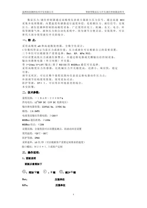
数显压力/液位控制器通过高精度仪表放大器放大压力信号,通过高速MCU 采集并处理数据,内置温度传感器进行温度补偿,是检测压力、液位信号,实现压力、液位监测和控制的高精度设备。
广泛使用在化工、机械、水文、电力、环保等测量气体、液体压力的自动化系统中。
因为调节方便灵活,安装简单,可以替代大部分使用液位开关的场合。
一、特点:采用高精度AD和高速微处理器,全数字化设计;4位数码管显示当前压力或液位值;压力或液位可以根据自己的需要设置;三个单位可以根据客户需要选择:Bar,KP,MPa/PSI;可以设置高低压力或液位报警点,并通过继电器或光耦输出给控制设备;输出双路继电器(单刀双掷)开关量;带4-20mA/0-10V/输出/基于RS485的MODBus通信可以选择。
采用高精度压力传感器,比机械压力开关精度高,迟滞小,响应快,稳定可靠;调节无死区,可以在整个量程范围内任意设定继电器动作压力点;外部调节结构使用简便,使用更加灵活;防护等级:IP65,可以用在环境恶劣的场合;本安防爆;二、技术参数:量程范围:-1BAR~200MPa供电电压:12~35V DC(24V DC 校准电压)输出继电器容量:220VAC/3A,24VDC/5A精度:±0.5%FS电流变送输出负载电阻:≥250ΩMODBus通信距离:≥100mMODBus结点:≤256设置范围:全量程段可以设置监测点,防波动回差设置使用温度:-20℃—85℃防护等级:IP65采样速率:10次/秒(可以根据客户需要定制要求的速度)接口螺纹:M20*1.5或客户定制三、操作说明:1、面板说明面板示意图如下:增加/⇧键:E键:减少/⇩键Bar:压强单位KPa:压强单位MPa/PSI:压强单位OUT1:高位报警指示OUT2:低位报警指示面板示意图2、字符说明:(AH)高位报警设置(AL) 低位报警设置(Unit) 单位转换(oA) 密码设置(ALo1) 高位报警点报警方式(ALo2) 低位报警点报警方式(HYA1) 高位报警点报警灵敏度(回差值)(HYA2) 低位报警点报警灵敏度(回差值)(dELy)继电器测试(QUIT) 退出菜单选项(oooo) 零点AD值校准设置(FULL) 量程上限对应AD值校准设置(--FU) 量程下限对应AD值校准设置(-_Ad) 校准量程下限对应AD值设置(FUAd)校准量程上限对应AD值设置(i_--)量程下限对应的电流输出设置(i_FU) 量程上限对应的电流输出设置(UP-0)高于零点显示为零点范围设置(dn-0) 低于零点显示为零点范围设置(oo)零点AD保存值查看(oS) 量程上限AD保存值查看(n-oo) 量程下限AD保存值查看(U-SL) MP/PSI单位选定(in-d) 显示小数点位置选择(u-r)测量量程下限(F-r)测量量程上限(in-A)零点修正设定值(Fi)满度修正设定值(FLtr)数字滤波时间常数值(oA1)报警设定值受密码控制选择(bout)故障代用值(oP)变送输出信号选择(bA-L)变送输出下限设置(bA-H)变送输出上限设置(bA-A)零点变送输出设定(bAFi)量程上限变送输出设定(nAFi)量程下限变送输出设定(ErrL) 传感器零点故障变送输出设定值(ErrH) 传感器满度故障变送输出设定值(oL)传感器检测值过高或过压显示(Err) 传感器检测值过低或欠压显示(E2rr) 读写存储器数据错误提示(addr) MODBus通信从机地址设置(bAUd)MODBus通信波特率设置3、按键说明:①:长按”E”键两秒为进入或退出各设置选项菜单功能键,如果进入某选项只是查看而不进行设置,则可长按“E”键两秒退出该选项的设置。
festo真空压力开关说明书PEV-1/4-B-OD费斯托 FESTO压力开关说明书的详细资料:费斯托FESTO压力开关说明书特点介绍:机械式压力和真空开关,切换点可调•气电转换器可调压力指示器或真空指示器,采用坚固的铸铝壳体以及符合 EN 175301-803 或 EN 60947-5-2 的插头。
机械式压力和真空开关可设置的开关点安装件:可旋入,用通孔或在高帽式导轨上用于设置压力的刻度•迟滞调节功能•带有切换状态显示•带标尺的派生型用于调节压力•多种安装方式可选测量方法气/电压力转换器工作和先导介质说明可用润滑介质工作(之后须一直润滑介质工作)介质温度 -20 °C ... 80 °C阈值设置范围 1 bar ... 12 bar防护等级 IP65耐腐蚀等级 CRC 2 - 中等耐腐蚀能力环境温度 -20 °C ... 80 °C开关元件功能转换开关工作压力 1 bar ... 12 bar工作介质压缩空气,符合 ISO 8573-1:2010 [7:-:-] 费斯托FESTO压力开关说明书FESTO型号:MFH-5/3G-1/8-B气缸FESTO ADVU-50-80-P-AMS4-WPB开关阀 MS4-EM1-1/4-S气动装置DFPD-80-RP-90-RD-F0507 费斯托FESTO双螺纹接头/NPFC-D-2G12-MSFAH-1B-Q4S-PNLK-PNVBA-M8VUVS-L25-B52-D-G14-F8-1C1MFH-3-1/2MSFG-24/42-50/6HGPT-35-A-BFESTO电磁阀161414 CPV10-M1H-5LS-M7JMFH-5-1/8-B。
压力开关使用说明书
压力开关是一种用于控制压力电路的装置。
它可以根据预设的压力值,监测压力的变化,并在达到设定值时切断或接通电路。
以下是压力开关的使用说明书:
1. 安装:请先确保断电,并将压力开关正确安装到压力管道上。
注意接口的紧固度和密封性,以确保压力传递和测量的准确性和可靠性。
2. 调整设定压力:使用调整螺钉,可以更改压力开关的设定值。
顺时针旋转调整螺钉将增加设定压力,逆时针旋转将降低设定压力。
在调整时应小心,并根据需要进行适当的测试和验证。
3. 连接电路:根据需要,将压力开关与控制电路连接。
确保正确连接电源和负载,以确保开关的正常工作和可靠性。
4. 运行监测:在正确连接电路后,可以应用压力到系统中,并观察开关的动作。
当压力超过设定值时,开关会切断电路或接通电路。
根据需要,可以通过相应的指示灯或报警装置进行监测和反馈。
5. 维护:定期检查和维护压力开关是必要的。
请检查接口的紧固度、密封性和电路连接是否正常。
清洁压力开关并确保其正常运行。
6. 安全注意事项:在操作和维护过程中,请务必注意个人安全。
请遵循相关的安全操作规程,并根据需要使用适当的个人防护装备。
RT Pressure switches incorporate a pressure controlled, single-pole change over swich where the contact position depends on the pressure in the connection port and the set value.The RT series consists of pressure switches, differential pressure switches and pressure switches for neutral zone regulation, all for general use within the industrial and marine segments. The series also covers safety pressure switches dedicated for steam boiler plants.For installations in which operation is particularly critical from safety and economic points of view, the use of fail-safe pressure switches is recommended.The use of gold-plated contacts is also recommended in such installations, provided operation involves only a few switching cycles or signal currents and voltages.Features• Simple design• High accuracy• High repeatability • Long operation life time• Available with all major marine approvalsData sheet | Pressure switch, RT Note:in addition we refer to the certificates, the copies of which can be ordered from Danfoss y CE marked in accordance with EN 60947-4/-5 for sale in Europey Further, the RT 19 , RT 30, RT 35, RT 112 W, RT 33, RT 31 and RT 32 series is CE markd in accordance with PED 97/23/EC, category IV, safety equipment.Approvals Overview/SurveyData sheet | Pressure switch, RTTechnical dataand code nos.When ordering, please state typeand code number.The type designationfor the letters below means:A: Unit suitable for the medium ammoniaL: Unit with neutral zonePressure switchesRT 113for manual setting;cover with windowsRT 116for tamper proof;cap and blank coverRT 262 ADifferential pressure switchPressure switches with adjustable neutral zoneDifferential pressure switches1)Supplied with ø6 / ø10 mm nipple. / 2)Non-snap action contacts (see spare parts and accessories, contact system 017-018166)3) With SPST and SPDT contact system for alarm and cut off function at 0.8 and 1 bar1) Supplied with ø6 / ø10 mm weld nipple1) Supplied with ø6 / ø10 mm weld nipple. / 2) With seal capPreferred versionsData sheet | Pressure switch, RT B: Safety units with external reset S: Safety units with internal resetThe designation letters mean:A: Units suitable for the medium ammonia.W: Units for control purposes.Pressure switches for steam plant, PED approved acc. to EN 12953-9 and EN 12922-11For rising pressureFor falling pressurePressure switches for low pressure steam plant (pressure monitoring)- not PED approvedTechnical data and orderingTechnical dataPreferred versionsData sheet | Pressure switch, RTMaterials in contact with the mediumMaterials in contact with the medium, PED approved switchesData sheet | Pressure switch, RTb. All other RT pressure switchesWhen the pressure falls to the set range value, contacts 1-2 make and contacts 1-4 brake. The contacts changeover to their original position when the pressure again rises to the set range plus the differential (see fig. 5).I. Alarm for falling pressure givenat the set range value.II. Alarm for rising pressure given at the set range value plus the differential.Units with min. reset can only be resetat a pressure corresponding to the set range value plus the differential.Functiona. RT 19, RT 30, and pressure switcheswith max. resetWhen the pressure exceeds the set range value, contacts 1-4 make and contact 1-2 brake. The contacts changeover to their initial position when the pressure falls to the range value minus the differential (see fig. 4). I.Alarm for rising pressure givenat the set range value.II. Alarm for falling pressure given at the set range value minus the differential.Units with max. reset can only be reset at a pressure corresponding to the set range value minus the differential, or a lower pressure.Data sheet | Pressure switch, RTExample 1An extra cooling water pump must start if the cooling water pressure falls below 6 bar, and must stop when the pressure exceeds 7 bar.Choose an RT 116 with a range of 1 – 10 bar and an adjustable differential of 0.2 – 1.3 bar.The start pressure of 6 bar must be set on the range scale. The differential must be set as the difference between the stop pressure (7 bar) and the start pressure (6 bar) = 1 bar. According to fig. 3, the differential setting disc must be set on 8.Example 2The burner on a steam boiler must cut out when the pressure exceeds 17 bar. Automatic restart must not occur.Choose an RT 19B with external reset. If extra safety is demanded, an RT 19S with internal max. reset can be used.The range is 5 – 25 bar and the differential is fixed at approx. 1 bar. The range scale must be set at 17 bar. After cut-out of the burner, manual reset is possible only when the pressure had fallen to the setting of 17 bar minus the differential: in this case, 16 bar and below.Example 3The min. permissible lubricating oil pressure for a gear is 3 bar. Reset must not be possible until the reason for oil pressure failure has been investigated. Choose an RT 200 with min. reset.The range value must be set while reading the range scale. Manual reset is possible only when the pressure has reached 3.2 bar (the differential is fixed at 0.2 bar or higher).Function (continuation)Functional description of RT unitswith fail-safe designFail-safe function for falling pressureFig. 5a shows a cross-section of a bellowselement for the RT 32W with fail-safe functionfor falling pressure. On rising pressure thecontact arm is actuated to break the connectionbetween terminals 1 and 2.On falling pressure the contact arm is actuatedto break the connection between terminals1 and 4. If a defect occurs in the bellows thesetting spring actuates the contact arm to breakthe connection between terminals 1 and 4, asin the case of falling pressure. This will occurirrespective of the pressure on the bellows.Fail-safe function for rising pressureFig. 5b shows a cross-section through a bellowselement for the RT 30W with fail-safe for risingpressure. On rising pressure the contact armis actuated to break the connection betweenterminals 1 and 2 .If a defect occurs in the inner bellows thepressure is led to the outer bellows. The outerbellows has an area three times as large as theinner bellows. The connection between terminals1 and2 becomes broken.If a defect occurs in the outer bellows, there willbe atmospheric pressure in the gap between thetwo bellows. This actuates the contact system tobreak the connection between terminals 1 and2. The important factor with the double bellowsdesign is the vacuum between the two bellows,and that in case of bellows break, no media willleak into the environment.Fig 5aFig. 5bData sheet | Pressure switch, RTPressure switches for liquid level control RT 1133. Connection to the side of the tankwith the RT 113 below the liquid levelWhere possible, this form of connection shouldbe used. If an air-absorbing liquid like oil isinvolved, it is preferable to 1 and 2. The resultingrange setting is the distance from the liquidsurface to the centre of the diaphragm housing.4. Connection in the tank with the RT 113above the liquid levelThis method is for use with air-absorbing liquidswhere connection type 3 is not possible. Theshortest horizontal tube length is determinedas described in 2. A shut-off valve is installedbetween the oil tank and water reservoir shownso that impurities can be drained from the waterreservoir through a bottom drain plug. Freshwater can then be poured into the reservoirthrough a filling connector in its top.The RT 113 pressure switch can be usedto control the liquid level in open tanks.Fig. 6 shows in principle, four different typesof installation.1. With air bell (see “Accessories”)For control purpose, the air bell should beinstalled 20 – 40 mm below the lowest liquidlevel. In addition, the tube between the RT 113and the air bell must be absolutely airtight. Ifonly an indication is required, the bell can beplaced 100 mm below the max. level. The RT 113must be set at 0 cm wg and the differential discon 1.2. Connection to the side of the tankwith the RT 113 above the liquid levelThe horizontal tube A must have a certain lengthin relation to the vertical tube B in order toensure reliable control. The length ofA can befound from fig. 7, using B and the range settingpressure C.Data sheet | Pressure switch, RT Application5. Setting knob 9. Range scale40. Neutral zone discRT-L pressure switches are fitted with a switch with an adjustable neutral zone. This enables the units to be used for floating control.The terminology involved is explained below.Floating controlA form of discontinuous control where thecorrecting element (e.g. valve, damper, or similar) moves towards one extreme position at a rate independent of the magnitude of the error when the error exceeds a definit positive value, and towards the opposite extreme position when the error exceeds a definite negative value.HuntingPeriodic variations of the controlled variable from the fixed reference.Neutral zoneThe interval in the controlled variable in which the correcting element does not respond (see fig. 13)The contact system in neutral zone units cannot be exchanged, as the contact system adjustment is adjusted to the other parts of the unit.Setting of neutral zoneThe range is set using the setting knob (5) fig. 8 while reading the range scale (9). The pressure set is the break pressure for contacts 1-4 (see fig. 13).The required neutral zone can be found in the diagram for the unit concerned. The position at which the neutral zone disc (40) must be set can be read from the lower scale in the diagram. The function can be seen in fig. 13.Data sheet | Pressure switch, RTExampleTogether with a VLT® static frequency converter, RT 200L neutral zone pressure switches can be used for the infinite control of a pump in, for example, a pressure boosting plant.In this case, the pump must be up and downregulated at 32 m and 25 m wg.The RT 200L must be set using the setting knob (5) fig. 8 page 9 at 3.5 bar (35 m wg) minus the fixed differential of 0.2 bar.The range setting is 3.5 - 0.2 = 3.3 bar.The neutral zone, 35 - 32 = 3 m wg,corresponding to 0.3 bar, must be set on the neutral zone disc (40) fig. 8 page 9. According to the diagram fig. 12 the disc setting is 1 or just over. A more accurate setting can be obtained by using the test setup shown in fig. 14.Setting of neutral zone© Danfoss | DCS (jmn) | 2016.06Data sheet | Pressure switch, RT IC.PD.P10.B6.02 | 520B7310 | 11ApplicationControl and monitoring of pressure differentials A differential pressure switch is a pressure controlled switch that cuts in and cuts out the current dependent on the pressure differential between the counteracting bellowselements and the set scale value. This unit is also available with an adjustable neutral zone (like the RT-L which is described on page 9.The setting disc (5) becomes accessible when the front cover is removed. The differential pressure is set by turning the disc with a screwdriver while reading the scale (9).For differential pressure switches with a changeover contact system, the contactdifferential is given as the differential pressure switches have a fixed differential. In units with an adjustable neutral zone, the neutral zone disc must also be set. See diagram in fig. 16.5. Setting disc 9. Range scaleSettingNote :When installing, the low pressure connection (LP) must always be upwards© Danfoss | DCS (jmn) | 2016.06Data sheet | Pressure switch, RT 12 | 520B7310 | IC.PD.P10.B6.02Functiona. Units with changeover switch (SPDT)b. Units with adjustable neutral zone (SPDTNP)If the differential pressure rises above the set value plus the differential, contacts 1-4 make.If the pressure falls by the amount of thedifferential (which is fixed in this unit), contacts 1-4 break. If the pressure falls to the neutral zone minus the differential, contacts 1-2 make. When the differential pressure rises again by an amount corresponding to the differential, contacts 1-2 break again.The contact function can be summed up as follows:I. Setting disc set for falling differential pressure.II. Neutral zone disc set for rising differential pressure.Example 1When the differential pressure exceeds 1.3 bar, a filter needs cleaning. The static pressure over the filter is 10 bar.According to the ordering table on page 4, the choice is an RT 260A (the RT 262A has a max. operating pressure on the low pressure side (LP) of 6 bar and is therefore not suitable for this application).Setting: Since a signal is required for rising differential pressure, the setting becomes 1.3 - 0.3 bar = 1.0 bar.Example 2The speed of a circulation pump must becontrolled to give a constant differential pressure of 10 m wg in a heating plant. The static plant pressure is 4 bar. The choice is an RT 262AL.The differential disc (5) fig. 15 page 13, must be set at 1 bar (10 m wg) minus the fixed differential of 0.1 bar, i.e. 0.9 bar. The neutral zone disc is factory-set (marked in red).I. Contacts make when differential pressure falls below the range scale setting.© Danfoss | DCS (jmn) | 2016.06RT 260A / RT 260ALRT 262A / RT 262A /RT 263ALData sheet | Pressure switch, RT IC.PD.P10.B6.02 | 520B7310 | 13Dimensions [mm] and weights [kg]Data sheet | Pressure switch, RT Spare parts and accessoriesSwitches1)At load types with low currents/voltages contact failure may occure on the silver contacts because of oxidation. In systems where such a contact failure is of great importance (alarm etc.), gold plated contacts are recommended.Contact systems for neutral zone units are not available as spare parts. Exchange not possible, as the contact system adjustment is adjusted to the other parts of the unit.The switch contacts are shown in the position they assume on falling pressure/temperature, i.e. after downward movement of the RT main spindle. The setting pointer of the control shows the scale value at which contact changeover occurs on falling pressure/temperature. An exception is switch no. 017-403066 with max. reset where the setting pointer shows the scale value at which contact changeover occurs on rising pressure.Data sheet | Pressure switch, RT© Danfoss | DCS (jmn) | 2016.06IC.PD.P10.B6.02 | 520B7310 | 15© Danfoss | DCS (jmn) | 2016.06Data sheet | Pressure switch, RT 16 | 520B7310 | IC.PD.P10.B6.02RT units have two mounting holes which become accessible when the front cover isremoved. Units fitted with switch 017-018166*) must be installed with the setting knob upwards. When installing differential pressure switches, the low pressure side (marked LP) must be installed upwards.The other pressure switches in the RT series can be installed in any position, expect that on plant subjected to severe vibrations it is advantageous to have the screwed cable entry downwards.*) Contact system with snap-action contact. See spare parts and accessories, page 13.Pressure connectionWhen fitting or removing pressure lines, the spanner flats on the pressure connection should be used to apply counter-torque.Steam plantTo protect the pressure element against temperature in excess to the maximumtemperature of the medium 150 °C (RT 113 90 °C), the insertion of water-filled loop is recommended. Water systemsWater in the pressure element is not harmful, but if frost is likely to occur a water-filled pressure element may burst. To prevent this happening, the pressure control can be allowed to operate on an air cushion.Media resistanceSee table of materials in contact with the medium. If seawater is involved, diaphragm pressure switches types KPS 43, KPS 45 and KPS 47 are recommended.PulsationsThe pressure switch must be connected in such a way that the pressure element is affected by pulsations as little as possible. A damping coil can be inserted (see “Accessories”). With strongly pulsating media, diaphragm pressure switches types KPS 43, KPS 45 and KPS 47 can be advantageous.Installation5. Setting knob 9. Range scale19. Differential setting disc SettingThe range is set by using the setting knob (5) while at the same time reading the scale (9). Tools must be used to set pressure switches fitted with a seal cap.In units having a fixed differential, the difference between cut-in and cut-out pressures is of course determined. On units having an adjustabledifferential the front cover must be removed. The differential disc (19) must be set in accordance with the diaphragm.Fig. 1. Positioning of unit© Danfoss | DCS (jmn) | 2016.06IC.PD.P10.B6.02 | 520B7310 | 17Selection of differentialTo ensure that the plant functions properly, a suitable differential pressure is necessary. Too small a differential will give rise to short running periods with a risk of hunting. Too high a differential will result in large pressure oscillations.Differential scale values are guiding.Installation。
OildynePressure SwitchesFor AC Power3.4-345 bar (50-5000 psi) RangeTypical ApplicationsPressure switches sense when a pre-selected fluid pressure is reached or lost and make or break an electrical circuit. Their operation can stop or start a machine’s cycle, actuate indicator lights or sequential operations. Properly installed, their operation is auto-matic and limited by your imagination and need.• Spring rangeDuplex models contain two separate switches which can be activated by one or two sensing ports depend-ing on the subplate configuration. See dimensional data for options.• environmentally resistantEnvironmentally resistant models are available on spe-cial order for certain hazardous location service.SubplatesSubplates are available for in-line mounting of Oildyne pressure switches. This allows further flexibility in mounting to existing equipment. Ports in 1/8 NPT or 7/16-20 (SAE-4) straight thread are standard. The duplex switch has two types of subplates, one with a port for each side of the switch, the other with one port only, for both sides of the switch.Pressure Switch Features• VersatileOur designs allow the switches to be used in any mounting orientation. They can sense hydraulic fluid pressure or air/gas pressure. A simple spring change allows the same basic switch to be used through a wide range of pressure settings.• durableHeavy-duty electrical contacts are rated for 15 amps at 125, 250 or 460 VAC. Normally open and normally closed contacts are provided.• reliableRepeatability is accomplished through a combination of a PTFE seal and a hardened, nickel-plated steel piston. This use of low-friction materials and the de-sign of the unique PTFE seal (or diaphragm*) prevents the piston from sticking. Repeatability, sensitivity and reliability are excellent. Limited piston movement pre-vents inertial forces from damaging the piston stop.*Used for lower pressure differential applications.Single Switchduplex Switchtriplex SwitchPRESSURE SETTING EASYMAKES CHANGINGADJUSTING SCREW LEAK PROOF OPERATION O-RING SEAL FOR1/2" PIPE CONDUIT CONNECTIONALL ALUMINUM CONSTRUCTIONELECTRICAL CONNECTIONSFOR ACCESS TOEASILY REMOVED COVER AND NORMALLY CLOSED CONTACTSSWITCH WITH NORMALLY OPEN HEAVY DUTY ELECTRICALAND ZERO LEAKAGE MINIMUM FRICTION PTFE SEALS FOR SPRINGDRAIN LINES NEEDEDSEALED PISTON, NO DISC OR DIAPHRAGMSINTERED METAL STAINLESS STEEL construction44Catalog HY22-1121/USfeatures and applications Pressure SwitchesParker Hannifin Corporation Oildyne DivisionMinneapolis, MN 55428 USA45DimensionsSingle Pressure SwitchSubplates (Single & duplex)Catalog HY22-1121/USdimensions Pressure SwitchesParker Hannifin Corporation Oildyne DivisionMinneapolis, MN 55428 USA46DifferentialThis is the pressure required to open and close theswitch contacts. It is a constant value dependent on the characteristics of the switch. The differential will be in the range as shown on the above table. For minimum differential, select the lightest spring including the maxi-mum setting desired.Spring Selection GuideSingle SwitchPK-01B Subplate (1/8” Pipe)PK-50B Subplate (SAE-4 Str. Thd.)duplex SwitchPK-01C Subplate (1/8” Pipe) Two PortsPK-50C Subplate (SAE-4 Str. Thd.)Two Ports PK-01D Subplate (1/8” Pipe) One Port PK-50D Subplate (SAE-4 Str. Thd.)One Porttriplex Specify Subplate PK-50H (SAE-4Str. Thd.) and Three Single SwitchSpecifications from Chart at Left.Standard Product Ordering CodeCatalog HY22-1121/UStechnical Information Pressure Switchesnote: 100 psi = 6.9 bar.Parker Hannifin Corporation Oildyne DivisionMinneapolis, MN 55428 USASpring numberSpring range adjustment range repeatability Plus or Minusdifferential range Spring color 150 - 100 psi 50 to 100 psi 2 psi 50 to 90 psi Green 2100 - 300 psi 75 to 300 psi 4 psi 50 to 100 psi Black 3300 - 500 psi 150 to 500 psi 5 psi 50 to 125 psi Red 4500 - 1000 psi 200 to 1000 psi 8 psi 50 to 150 psi Blue 51000 - 2000 psi 300 to 2000 psi 15 psi 75 to 250 psi White 62000 - 3000 psi 400 to 3000 psi 20 psi 75 to 250 psi Yellow 73000 - 4000 psi 500 to 4000 psi 25 psi 125 to 350 psi Orange 84000 - 5000 psi500 to 5000 psi50 psi150 to 450 psiPink。
目录1 说明§1.1 重要说明§1.2 开关标识2 探测头安装§2.1 压力与真空探测头§2.2 差压探测头§2.3 温度探测头3 封装外壳的安装§3.1 “C”型外壳§3.2 “Z”型外壳§3.3 “V”型和“W”型外壳§3.4 “M”型外壳4 电气安装5 设定点调节6欧共体标准符合说明1 说明§1.1 重要说明* BETA压力开关属于精密仪器请正确放置或搬动。
BETA压力开关在达到设定点的(差压)压力或者温度时开关动作。
* 在按照说明书指示正确安装,该开关的设计与结构是完全免维护的。
切莫采用液态油或油脂润滑开关的任何部件。
* 除了更换外壳密封与安装支架外,不要移动或更换本开关的任何部件。
* 避免暴露在超高温、超低温、有侵蚀性环境中,-30~80℃为适宜温度。
* 调节螺丝有自锁性,所以在调节设定点后禁止封死调节螺丝。
* 安装前请详细检查铭牌上数据。
* 所有尺寸均以mm毫米标注。
* 如果您需要帮助请与供应商联系,开关只有在去污清洗后才能进行维护检修。
* 如果您需要额外的膜片O形圈和微动开关,请给出序列号向供应商购买。
* 开关的检修维护请由专业的仪表工程师实施。
除了更换膜片O形圈和微动开关以外,其它形式的检修维护有厂方执行。
* 非厂方检修维护的操作会影响产品本身的质量保证。
* 本章节的指导说明书的步骤也是安装步骤说明。
* 地基与工程环境的强烈振动可能会影响开关的正常功能。
§1.2 开关标识压力开关的铭牌上面标明了规格型号,4到7步可以确定该压力开关的设计组成,后缀的X+数字来表明特殊要求,该特殊要求可参照数据书。
外壳封装C1-P304L-S1N-B1-K1-Y-X2第一个字符即第一步标明了外壳封装形式:C、V、W、Z或M,参照图1-4和15。
探测头C1-P304L-S1N-B1-K1-Y-X2第一个和最后一个字符构成第二步标明了探测头规格及功能,参照图5-12和表1。
机械式压力开关
型号:MD-S700
量程:0-25Bar
设定压力:10Bar
产品材质:不锈钢
量程:ZG1/4
出厂日期:
检验人员:
在使用本压力开关之前必须详细阅读此压力开关的有关资料和操作说明。
该系列压力开关为机械式压力开关,当流体压力作用在感压力元器件,使之产生形变,将向上移动,通过栏杆弹簧等机械结构,最终启动最上端的微动开关,使电信号输出。
该系列压力开关内部采用全不锈钢感压膜片,它的特点是使用方便,工作稳定,机械寿命长。
用户可通过随产品的附件工具设置控制点,或者是出厂时要求我厂预设好压力控制点。
该系列产品应用广泛,特别适合自动化设备配套,矿山机械等应用机械的压力控制及保护。
一.产品参数
产品量程0~0.2...1230Bar (根据客户选择不同,量程有差异)
设定压力0~0.2...600Bar (根据产品的量程不同,设定范围有差异)
测量介质水、油、气体等对不锈钢无腐蚀的流体
电气触点镀银
设定延时膜片式约为10% 活塞式约为15%
最高行程90次/秒
工作温度-20℃~80℃
机械寿命106 次
认证方式CE认证
重量60g
电气特性
可变式开关逻辑:常开和常闭
电源保护:根据DIN 40050标准
电源连接:根据DIN 43650标准
接线保护反极性和短路保护
安装接口G1/4 G1/2 或用户定制
材质不锈钢
二.连线方法
端子 定义
最大载荷
红色 报警公共端(COM 端) DC42V1A DC125V0.2A
AC42V3A AC125V3A
黑色 报警常开端(NO 端) 蓝色
报警常闭端(NC 端)
连线前必须确定使用电路中的电流电压是否超过压力开关的额定载荷! 连线时,必须切断电源以免造成人身伤害和产品的损坏!
三.尺寸图及电气连接图
*因防爆等级及客户要求不同,外形有差异。
四.注意事项
1.不得施加超过产品额定承载的压力!
2.不得通过超过产品额定承载的电流及电压!
3.不得测量对不锈钢或铜有腐蚀的介质!
4.不得带电连线或调节压力设定点!
5.强烈的碰撞可能会影响设定值,甚至会损坏产品。
6.防爆型产品在连线完成后,必须安装好产品的接头外壳及防护罩。
★ 因客户所订购的产品不同,本使用说明书可能有部分参数或内容与客户所收到的产品略微不
同,本说明书仅供参考,如发现问题,请与供应商联系。