KITA压力开关说明书
- 格式:pdf
- 大小:1.55 MB
- 文档页数:4

操作手册压力继电器(压力开关)YSJ-340系列一、概述YSJ-340系列压力继电器是一种超小型压力控制仪表,用于液压、气动系统的压力显示与控制,可替代德国贺德克HYDAC(贺德克)EDS300系列压力继电器。
该仪表采用了高精度压力传感器,电路部分以高性能单片机微处理器为核心,具有3位LED数字显示及轻触开关输入的人机界面、具有开关量(报警)输出及4~20mA模拟输出,是在机械继电器无法胜任的条件(如压力剧烈波动、强环境振动、高精度高速度控制、小体积等)下可靠工作的理想选择。
二、性能指标◇测量范围:0~1.6—0~60MPa◇电源电压:16~36VDC◇输出信号:(RL≤250Ω)◇接口螺纹:G1/4◇环境条件:环境温度:-20℃~60℃介质温度::-20℃~80℃存储温度 :-40℃~125℃相对湿度:0~80%耐冲击:≤50g/ms耐振动:≤10g/(0~500HZ)◇输出信号精度:1.0◇过载压力:1.5%倍满量程压力◇最大功耗:≤3W触点容量:24VDC/1.2A(MAX)三、功能根据不同型号,装置可提供下列功能◇三位显示当前压力(正常工作)◇按压力、预设开关点输出开关量◇输出模拟量◇基本设定菜单◇提供四种不同输出模式:◇YSJ341带1路开关量输出(负载最大电流1.2A,无模拟量输出)◇YSJ342带2路开关量输出(负载最大电流1.2A,无模拟量输出)◇YSJ343带1路开关量输出(负载最大电流1.2A)和1路模拟量输出(4~20mA)◇YSJ344带2路开关量输出(负载最大电流1.2A)和1路模拟量输出(4~20mA)四、安装YSJ340可以通过压力管接头(DIN3852内螺纹G1/4),直接装在液压集成快上。
电气连接必须由国家认定合格的电工操作(参考中国电工国家标准规范)。
压力继电器的外壳必须同时良好的接地。
如安装在液压块里,块体通过液压系统接地时有保证的。
若用微型软管安装,客体必须单独接地。
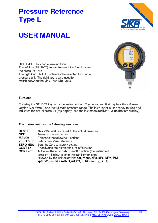
Pressure ReferenceType LUSER MANUAL ArrayREF TYPE L has two operating keys.The left key (SELECT) serves to select the functions andthe pressure units.The right key (ENTER) activates the selected function orpressure unit. The right key is also used toswitch between the Max.- and Min.-value.Turn-on:Pressing the SELECT key turns the instrument on. The instrument first displays the software version (year/week) and the fullscale pressure range. The instrument is then ready for use and indicates the actual pressure (top display) and the last measured Max.-value (bottom display).The instrument has the following functions:RESET: Max.-/Min.-value are set to the actual pressureOFF: Turns off the instrumentMANO: Releases the following functions:ZERO SEt: Sets a new Zero referenceZERO rES: Sets the Zero to factory settingCONT on: Deactivates the automatic turn-off functionCONT off: Activates the automatic turn-off function (the instrumentturns off 15 minutes after the last key function)followed by the unit selection: bar, mbar, hPa, kPa, MPa, PSI,kp/cm2, cmH2O, mH2O, inH2O, ftH2O, mmHg, inHgExample: Setting a new pressure unit (mbar):--> Turn on the instrument by shortly pressing the SELECT-key.--> Wait for the instrument’s measuring mode (approx. 3 seconds).--> Press the SELECT-key 3 times: MANO appears.--> Press ENTER: ZERO SEt appears.--> Press SELECT: ZERO rES appears.--> Press SELECT: CONT on or CONT off appears.--> Press SELECT: bar appears.--> Press SELECT: mbar appears.--> Press ENTER: The new pressure unit (mbar) is set.The instrument returns to the measuring mode.Display of the minimum pressure value:When in the measuring mode (Display: Actual Pressure and Max.- value), you may display the Min.-value for 5 seconds by shortly pressing the ENTER-key.Notes:• The functions and units can also be called up by keeping the SELECT-key depressed. Releasing the key enables the displayed function or unit to be activated with the ENTER-key.• If the selected function or unit is not activated within 5 seconds with the ENTER-key,REF TYPE L returns to the measuring mode without changing any settings.• Turning REF TYPE L on and off does not influence any of the previous settings.• If the CONT on function is activated, it is indicated with a flashing sign (cont) on the display.• If a pressure can not be represented on the display, OFL (overflow) or UFL (underflow) appears on the display.• If the actual pressure goes beyond the measuring range, the last valid pressure value starts flashing on the display.Installation:Screw the G1/4 male port of REF TYPE L into the female pressure port and tighten using the lower hexagon of the transducer. Loosen the upper hexagon and rotate the REF TYPE L to the desired position.Restraighten:The face of REF TYPE L can be rotated through 355°. This feature allows the REF TYPE L to be mounted in all possible positions; vertical, horizontal or upside down.Battery Change / Battery Life:When the battery starts weakening, a low battery warning will appear (BAT LOW). Battery change (turn off the instrument before changing the battery!):Open the battery compartment and change the battery (type CR 2430). Make sure that the O-ring remains embedded in the cover. The battery life is 2000 hours in normal measuring mode. Ranges / Calibration:The factory setting of the Zero for the ranges ≤61 bar is at 0 bar absolute. For sealed gauge pressure measurements, activate “ZERO SEt” at ambient pressure.Instruments with ranges >61 bar are calibrated in a sealed gauge mode at ambient pressure.Interface (RS485):The interface converter K103A (RS232) or K104A (USB) can be connected at the back of the manometer, allowing the data transfer to the PC.。

P2系列双显数字压力开关使用说明书一、主要特点:1、开放式仪表参数设定2、采用防水结构,外形美观、安装方便;3、设定参数密码锁定,断电后永久保存。
4、同时显示动作点压力值(SV)与当前压力值(PV)二、技术参数·压力范围:0~0.5Kpa…50Mpa·控制精度:±1字·过载能力:1.5倍·动作时间:不超过1ms·使用环境:环境温度 0~50℃相对湿度≤85%RH避免强腐蚀气体·测量精度:0.5%FS ±1字·分 辨 率:1、0.1、0.01字·工作电压:DC24V·功 耗:≤5W·显示方式:-199~999测量值显示-199~999设定值显示·结 构:铝盒密封安装,防水·螺纹接口:M20 x 1.5·控制方式:两路开关量输出,可设置动作点、上/下限动作、回差/带差继电器控制模块(用户可选):0.3A at 220VAC;2A at 30VDC 三极管控制模块(用户可选):1.5A at 30VDC双向可控硅制模块(用户可选):5A at 250VAC·参数设定:面板轻触式按键数字设定,参数设定后永久保存。
参数设定值密码锁定 ·保护方式:继电器输出状态LED指示电源欠压自动复位工作异常自动复位(Watch Dog)三、操作方式1、正确的接线请参照仪表随机接线图(见附录)接妥输入、输出信号线及电源线,并请确认无误。
2、仪表的上电本仪表无电源开关,接入电源即进入工作状态。
四、控制参数设定 (一)、仪表面板项 目 功 能PV 显示测量值 显示实时测量值 显示AL1动作值与AL2动作值显 示 器 SV 显示动作点在参数设定状态下,显示参数符号或设定值按压然后抬起按下不放保持5秒 SET 参数设定键1) 在显示模拟量输出值时则进入一级参数设定,显示参数CLK 符号。
kita数显压力表使用说明书一、数显压力表使用方法:1、开关机:长按“开/关”键≥2秒,开机或关机。
2、清零:当仪表没有压力的情况下,出现零漂,可短按“清零”键即可清零。
3、满量程查询与单位切换:长按“清零”键≥2秒,可看到最大满量程;此页短按“开关”键,切换压力单位,长按“设置”键≥2秒,保存选择好的压力单位;长按“清零”键≥2秒,退出至主页。
二、数显压力表环境注意事项:1、现场使用条件应符合数显压力表技术参数的要求。
正确选用仪表量程,被测压力不能超过仪表的测量上下限范围,应留有充分的超压安全余量。
2、被测介质温度不得超过数显压力表的工作温度范围,在腐蚀、振动场所使用时还应确保仪表的密封及耐振性能。
3、仪表为垂直向下直接安装式,可直接安装在被测管道压力接口上,安装时避免仪表连接螺纹与表前阀之间形成“封闭压力"(观察示值,注意有压力响应时间),如果形成该压力,应及时消除,否则会造成测量元件损坏、介质泄漏。
三、数显压力表操作说明:数显压力表的传感器与显示处理部分采用一体化的设计结构,使用简便,该仪表与被测机构使用螺纹直接连接的方式,对仪表的摆放角度不做任何要求。
在使用测量以前应该估算被测量目标的大致压力范围,以免由于压力过大超出测量范围对传感器造成机械上的损坏。
数显压力表的压力响应时间为2S。
四、数显压力表现场环境注意事项:数显压力表属于机电产品,使用了液晶显示技术,在强光下使用会减少液晶屏幕的使用寿命,而且可能会使数据辨认不清楚,由此造成的事故后果,本公司不负任何责任。
仪表接液部分为不锈钢金属材料和扩散硅传感器,测量强酸,强碱的介质应选取用隔膜型数字压力表。
数显压力表使用不可充电的锂电池,使用过后的电池应妥善处理(可邮寄回本厂统一处理)以免造成环境污染。
在高温或低温的情况下使用(大于85℃,小于-30℃)时,超过85℃应加散热器,否则测量度无法保证,而且过高的温度情况下锂电池有爆炸的危险,在存储或运输的过程中也应该注意仪表温度。

第一章SET220K系列全站仪的使用一)、操作面板主要按键✧[ ON ]键:电源开关✧[ ]键:打开或关闭背光✧[]键:左移光标或选择选项✧[ ]键:右移光标或选择选项正常开机:[ ON ]热启动开机:[ F 4 ] + [ BS] + [ON] (仪器参数初始化)冷启动开机:[ F 1 ] + [ F 3 ] + [ BS] + [ON] (清除内存全部数据,恢复出厂设置)二)、基本模式菜单结构基本模式测量模式测量的各种操作内存模式文件、已知坐标和代码操作设置模式仪器参数设置、键功能定义等操作✧[ESC]键:返回前一菜单✧[SFT]键:键盘输入模式转换✧[BS]键:删除前一字符✧[FUNC]键:菜单翻页✧{F1~F4}:选取软键对应的功能12、线路计算SET130R系列是索佳最近推出的新型免棱镜全站仪系列,该系列全站仪除具有350m高精度远距离免棱镜测程、可见激光指示和红绿光导向等新功能外,线路计算是其强大软件功能特色之一。
线路计算功能可运用于土木、道路等工程中各种线路点、道路中桩点和边桩点平面坐标的计算,并可直接将计算结果记录至仪器内存文件中或在实地实施放样测量,方便了用户并极大地提高作业效率。
线路计算中提供了直线计算、圆曲线计算、回旋曲线计算、三点计算法、一点转角计算法和系列计算法等计算功能,其中前三种方法用于单线元线路桩点坐标的计算,后几种方法用于多线元线路桩点坐标的计算。
线路计算包含线路定义、中桩点坐标计算、边桩点坐标计算、坐标存储和桩点放样测量几个过程,为便于大家对该功能的了解,本文分别就这些计算方法及其处理过程做一详细介绍。
一、直线计算直线计算用于由单一直线构成的线路桩点平面坐标的计算。
计算时以直线起点BP为基准点P1,已知数据为基准点P1的坐标、交点IP的坐标或直线的方位角AZ,线路如下图所示:✧线路定义输入基准点P1和交点IP两点的坐标或者基准点P1的坐标和至交点IP方向的方位角AZ对线路进行定义。
![智能型数显压力开关使用说明书-A4[整理]](https://img.taocdn.com/s1/m/431d7764f342336c1eb91a37f111f18583d00c1d.png)
六、指示灯定义及工作状态说明电源指示灯接通电源后常亮上限指示灯进行上限设置过程时长亮,在运行状态中,当压力高于上限,上限指示灯长亮。
下限指示灯进行下限设置过程时长亮;在运行状态中,当压力低于下限,下限指示灯长亮。
单位指示灯默认单位为MPa,MPa、Kg/cm2、PSI可任意切换。
运行指示灯闪烁控制器处于运行状态中,继电器处于闭合状态。
常亮控制器处于运行状态中,继电器处于断开状态。
不亮控制器处于设置状态,继电器处于断开状态。
七、显示代码说明字符字符定义E--E 表示传感器损坏或电线连接不正确。
E--1 表示控制器在工作状态下,持续3分钟压力未变化,按任意键返回运行状态。
E--2 当前压力超过(上限+0.1MPa),按任意键返回运行状态。
C--L 表示正在清零操作。
E--H 超过压力控制器的最大量程。
8888数据设置存储成功标志。
八、注意事项1.收到产品后,请检查包装及外形是否完好,并核对型号和规格是否与您选购的产品相符。
2.按产品所提供的过程连接、电气连接和安装方式,将产品正确可靠安装并接线。
3.请勿带电安装!4.使用过程中请注意产品的技术规范和使用条件,如允许的介质温度、过载压力、供电电压等。
5.压力开关属于精密器件,用户在使用时请不要自行拆卸,更不能用硬物触碰膜片,以免造成产品的损坏。
6.在安装过程中,注意保护产品,不得强力安装或者拆卸,否则容易损坏产品,特别是安装螺纹。
7.安装时请用合适的扳手安装或拆卸,不得强行用手拧动壳体来拧紧或者拆卸,否则造成的损害不在保修的范围内。
8.安装后通电测试,出现非正常现象,除非具备产品调节设备和技能,否则请将产品联系我公司的售后技术人员。
智能型数显压力开关Intelligent digital pressure switch智能型数显压力开关是集压力的测量、显示、控制于一体的智能化控制仪表,具有操作简单、价格便宜、抗震动、控制精度高、使用寿命长等特点。
该压力开关具有延时控制功能、三种显示单位可以任意切换、误差一键清零等多种功能。
ZSE30/ISE30系列压力开关设定说明一、在测试模式下(即显示实际压力值的状态下)按住SET键2秒以上,进入初始设定。
完成初始设定需以下几个步骤:1、进入初始设定首先显示“显示颜色设定”的选定值,可通过△、▽键更改设定。
待选项有以下四种:、①Sor:ON时红(选择此项)②SoG:ON时绿③rEd:一直红④Grn:一直绿2、选好后按SET键保存并进入“动作模式设定”,共有两种动作模式:①HYS:迟滞模式(选择此项)②Ynd:上下限比较模式通过△、▽键可以任意选定3、选好后再次按SET键将进入“输出形态设定”,两种输出形态供选:①no:常开(选择此项)②nC:常闭两种输出形态通过△、▽键来选择4、选好后按SET键将进入“响应时间设定”,有四种响应时间,利用△、▽键可选:①2.5:2.5ms(选择此项)②20:20ms③160:160ms④640:640ms⑤1280:1280ms5、选好后按SET键将进入“自动预制设定”:①nAn:手动设置(选择此项)②AUt:自动设置通过△、▽键选定6、此时按再SET键将返回测试模式至此,初始设定完毕。
二、在测试模式下按一下SET键将进入手动数值设定界面。
此时[P_1]与设定值交替闪动。
如果想改变[P_1]的设定值可按△或▽键,此时数值末位闪动,按△或▽键可在0~9之间改变数值;按SET键上一位数值闪动,同样按△或▽键可在0~9之间改变此位数值,当更改好后,请不要按任何键等待十秒此数值将被设定成功。
此时[P_1]与设定值再次交替闪动。
如不想修改[P_1]的设定值或已修改好后按SET键进入固定迟滞的设定,此时[H]与固定迟滞的设定值交替闪动。
数值更改方法与上面介绍的修改[P_1]的设定值的方法相同,设定好后[H]与固定迟滞值交替闪动。
对[H]值未进行设定或设定好后再次按SET键则返回测试模式。
至此,手动数值设定完毕。
三、[P_1]与[H]的设定值在“HYS”迟滞模式中对压力开关信号输出的影响:若“输出形态设定”为“no”常开,当实际压力> [P_1]设定值时,压力开关输出on 信号;当on信号输出后,测试到的压力值若>{[P_1]- [H]},on信号被保持;随着压力的下降,当实际压力<{[P_1]- [H]}时压力开关输出信号变为off。
INSTRUCTION MANUALNI-209E版本:9 04/20DIFFERENTIAL PRESSURE SWITCHES SERIES DA & DW本手册提供的所有数据、声明和建议均基于我们认为可靠的信息。
由于有效使用条件超出了我们的控制范围,我们的产品销售条件是用户在遵循我们对其预期目的或使用的建议之前自行评价上述条件。
耐候且本质安全:DW 系列隔爆:DA 系列型号:DW40、DW100和DW160型号:DA40、DA100和DA160A 低压接头B 高压接头C 电缆入口重量6.2 kg (尺寸单位:mm )A 低压接头B 高压接头C 电缆入口重量7.2 kg (尺寸单位:mm )型号:DW10型号:DA10A 低压接头B 高压接头C 电缆入口 重量8.2 kg (尺寸单位:mm ) A 低压接头B高压接头C 电缆入口重量10 kg (尺寸单位:mm )对于表面安装,使用四个M6螺钉。
注意:除非在认证图纸上标注,否则尺寸和重量不是强制性的。
注意• 在安装、使用或维护仪表之前,有必要阅读并理解随附说明手册中给出的说明。
• 仪表必须由有资质人员进行安装和维护• 只有在检查并确认仪表特性符合工艺和设备要求后,才能进行安装。
• 仪器的功能特点及其防护等级显示在固定在外壳上的标识牌上。
内容:1 一般说明2 工作原理3 型号代码4 标识牌和标记5 设定值调节6 设置点校准7 安装和连接8 仪表管道9 安全完整性等级(SIL )安装要求 10 投入运行 11 目视检查 12 功能验证 13 停止和拆卸 14 处置 15 故障排除在危险环境中使用的安全说明。
压力开关安全使用建议。
1一般说明1.1前言系列或型号的错误选择以及不正确的安装会导致故障并缩短仪器寿命。
不遵守本手册中给出的指示可能会对仪表、环境和人员造成损害。
1.2允许的超量程压力可偶尔超过工作范围,前提是其保持在仪表特性(真空或设计压力)中规定的范围内。
Pressure SwitchesFEATURESCompact size316 stainless steel constructionP ressure ranges from vacuum to 15,000 psi F actory set or field adjustable setpoints W ide operating temperature range (–40°C to 100°C)Precision snap-acting micro switch SPDT or DPDT switching UL, CSA listed models CE and ROHS compliantCRN models available (up to 10,000 psi) SIL 3 capableSIL 3 CAPABLELOOK FOR THESE MARKS • High performance • S mall size • S pecial connections• E asily configurable to meet your application requirements • S IL 3 capableN4 1H 012CPressure SwitchesTO INCREASE SET POINT ROTATE RIGHT ––––>TO DECREASE SET POINT .095 OR SMALLER TOOL REQUIRED TO ROTATE NUTSETPOINT ADJUSTMENT. SLIDE COVER UP TO CLOSE AND SEAL ADJUSTMENTDIMENSIONSPressure SwitchesPRESSURE CONNECTIONSAVAILABLE CONNECTIONSELECTRICAL CONNECTIONS1/8, 1/4 or 1/2 MALE NPT 18 AWG WIRE LEADS1/2NPT CONDUIT CONNECTOR WITH 18 AWG WIRE LEADSSPADE TERMINAL 4-0.187 MALE TERMINALS HIRSCHMANN MICRO-DIN CONNECTOR 43650 FORM CDPDT 18 AWG LEADS1/8or 1/4 FEMALE NPT, 7/16-20 SAE FEMALE7/16-20 SAE MALE (OPTIONAL 37° FLARE END)3/4˝, 1.5˝ or 2.0˝ SANITARYVCR or VCO G 1/4 A TYPE-E STUD END 1/2 FEMALE NPT G 1/4 BM20 X 1.5 MALE CONDUIT WITH 18 AWG WIRES1/2NPT MALE CONDUIT AND JACKETED CABLE WITH 18 AWG WIRES M20 X 1.5 MALE CONDUIT ANDJACKETED CABLE WITH 18 AWG WIRESPressure SwitchesCutaway view of switch assemblywith welded SS diaphragmMICRO-SWITCHCIRCUIT BOARD ASSEMBLYPUSH RODDIAPHRAGMSPRING GUIDEMICRO-SWITCHCIRCUIT BOARD ASSEMBLYPUSH RODO-RINGSPRING GUIDEBefore selecting a switch the f ollowing should be considered:Actuator:The actuator responds to changes in pressure and operatesthe micro switch element in response to these changes. Theactuator is normally exposed to the process media and must be chemically compatible with it. There are three types of actuators available for the A-Series switches – all welded 316 SS dia-phragm sealed piston; 316 SS piston with Viton O-ring seal; and 316 SS piston with Buna-N O-ring seal. The 316 SS diaphragm is available in ranges from –15/15 psi to 200 psi. The 316 SSpiston is available in ranges from 100 psi to 15,000 psi. Switches offered in 100 psi and 200 psi can be ordered with either thepiston or diaphragm design. The piston design will have a longer mechanical life, while the diaphragm design has a better operat-ing temperature.The piston design is more reliable than a diaphragm designwhen subjected to frequent large pressure excursions, pressure surges and spikes associated with typical hydraulic applications. Piston designs are typically used when the switch is used as low pressure alarm or cutoff where the normal working pressure isabove the nominal range of the switch.The Switching Function:Most applications for alarm, shutdown and interlock are satis-fied by the standardA-Series switches which feature single setpoint fixed deadband. For pump, compressor and other control applications, the dead-band becomes a very important c onsideration and may require increasing the range of the switch to increase the deadband.Please consult your Ashcroft representative for assistance withspecial applications.The Micro Switch Element:The micro switch element must be chosen to meet the electrical load requirement to be switched. The switches are offered as either SPDT (single pole double throw) or DPDT (double pole double throw). The DPDT switch is made up of two SPDT switches which are adjusted to work together by Ashcroft’s patent pendingCircuit Board Rotation Design. DPDT switching is not available on diaphragm designs below 100 psi, withSpade terminals or the Micro DIN connector.Understanding Setpoints and Reset Points:Pressure switches can be set to switch on either increasing (rising) or decreasing pressures. Since theswitches have both Normally Open (NO) contacts and Normally Closed (NC) contacts you can wire the switch to open or close for either an increasing or decreas-ing pressure. To be consistent in setting the switch-es Ashcroft defines the setpoints as follows. For anincreasing setpoint, the pressure is increased from 0 psito the set point and then decreased to the reset point. For a decreasing setpoint, the pressure is increased to full range and then decreased to the setpoint and then increased to the resetpoint.Custom Applications: The A-series switch is designed to allow custom process connections and electrical terminations. Please consult your Ashcroftrepresentative for assistance with custom applications.Cutaway view of switch assembly with SS pistonSELECTION GUIDEPressure SwitchesAccuracy – (See repeatability) Accuracy normally refers to con-formity of an indicated value to an accepted standard value. There is no indication in switch products; thus, instead, the term repeatability is used as the key performance measure. Ashcroft A-Series switch accuracy is 2% of nominal range.Automatic Reset Switch – Switch which returns to normal state when actuating variable Pressure is reduced.Adjustable or Operating Range – That part of the nominal range over which the switch setpoint may be adjusted. Normally about 10% to 100% of the nominal range for A-Series pressure switches.Burst Pressure – The maximum pressure that may be applied to a pressure switch without causing leakage or rupture. This is approximately 16X of nominal range for A-Series switches. Diaphragm switches subjected to pressures above the nominal range can be permanently damaged.Deadband – The difference between the setpoint and the reset-point, normally expressed in units of the actuating variable. Sometimes referred to as differential.Fixed Deadband – The difference between the setpoint and the resetpoint of a pressure switch. It further signifies that this deadband is a fixed function of the pressure switch and not adjustable.National Electrical Manufacturers Association (NEMA) – This group has defined several categories of enclosures, usually referred to as “types.” Further, they designate certain features and capabilities each type must include.NEMA 6 – Enclosures constructed for either indoor or outdoor use to provide a degree of protection to personnel against access to hazardous parts; to provide a degree of protection of the equipment inside the enclosure against ingress of solid foreign objects (falling dirt); to provide a degree of protection with respect to harmful effects on the equipment due to the ingress of water (hose directed water and the entry of waterduring occasional temporary submersion at a limited depth); and that will be undamaged by the external formation of ice on the enclosure.Normal Switch Position – Contact position before actuating pressure (or variable) is applied. Normally closed contacts open when the switch is actuated. Normally open contacts close when the switch is actuated.Normally Closed – Refers to switch contacts that are closed in the normal switch state or position (unactuated). A pressure change opens the contacts.Normally Open Switch – Refers to the contacts that are open in the normal switch state or position (unactuated). A pressure change closes the contacts.Overpressure Rating(s) – A nonspecific term that could refer to either burst or proof pressure, or both.Proof Pressure – The maximum pressure which may be appliedwithout causing damage. This is determined under strict labora-tory conditions including controlled rate of change and tempera-ture: This value is for reference only. Consult factory for appli-cations where switch must operate at pressures above nominal range or reference temperature (70°F).Repeatability (Accuracy) – The closeness of agreement among a number of consecutive measurements of the output setpoint for the same value of the input under the same operating con-ditions, approaching from the same direction, for full-range tra-verses. Ashcroft A-series switch repeatability is 2% of nominal range.Note: It is usually measured as non-repeatability and expressed as repeatability in percent of span or nominal range. It does not include hysteresis or deadband.Resetpoint – The resetpoint is the Pressure value where the electrical switch contacts will return to their original or normal position after the switch has activated.Setpoint – The setpoint is the Pressure value at which the elec-trical circuit of a switch will change state or actuate. It should be specified either on increase or decrease of that variable. Single Pole Double Throw (SPDT) Switching Element – A SPDT switching element has one normally open, one normally closed, and one common terminal. The switch can be wired with the circuit either normally open (N/O) or normally closed (N/C). SPDT is standard with A-series switches.Double Pole Double Throw (DPDT) Switching Element – Two SPDT switching elements both set to actuate or de-actuate at the same set or resetpoint. Each switch one has one normally open, one normally closed, and one common terminal. Theswitches are independent of each other and can be wired to two independent circuits. The two circuits can either normally open (N/O) or normally closed (N/C).Snap Action – In switch terminology, snap action generally refers to the action of contacts in the switch element. These contacts open and close quickly and snap closed with sufficient pressure to firmly establish an electrical circuit. The term distin-guishes products from mercury bottle types that were subject to vibration problems.ADDITIONAL SWITCH TERMINOLOGYPressure SwitchesWorld HeadquartersAshcroft Inc.250 E. Main StreetStratford, CT 06614-5145 U.S.A.Tel: (203) 378-8281Fax: (203) 385-0408email:***************** International Operations BrazilWilly Instrumentos de Medicao e Controle Ltda.Rua Joao Pessoa, 62009520-000Sao Caetano Do Sul-Sao Paulo-Brazil Tel: 55-11-4224-7402Fax: 55-11-4224-7477email:********************.brChinaAshcroft Instruments (Suzhou) Co., Ltd.1508 Lin-hu AvenueAscendas Lin-hu Industrial Square Wujiang Fenhu Economic Zone Wujiang China, 215211Tel: 011-86-512-6326-9101Fax: 011-86-512-6326-9106 GermanyAshcroft Instruments GmbH Postfach 11 20, D-52490Baesweiler, GermanyMax-Planck-Strasse 1, D-52499 Baesweiler, Germany Tel: 49-2401-8080Fax: 49-2401-808 125email:******************www.ashcroft.euMexicoAshcroft Instruments Mexico, S.A. de C.V.General Mariano Arista No. 54 Nave 8Col. Argentina Poniente Deleg. Miguel Hidelgo 11230 Mexico City, Mexico Tel: 525-550-82-3030Fax: 525-550-82-3027email:**********************.mxSaudi Arabia AARICOP.O. Box 12031Jubail Industrial City 31961 Kingdom of Saudi Arabia Tel: 966-3-341-0278Fax: 966-3-341-7624email:***************SingaporeAshcroft Instruments Singapore Pte. Ltd.Block 1004 Toa Payoh North #07-15/17Singapore 318995Tel: 65-6252-6602Fax: 65-6252-6603email:**********************.sg United KingdomAshcroft Instruments LimitedUnit 17 & 18 William James House Cowley RoadCambridge CB4 0WX Tel: 44-0-1223-395500Fax: 44-0-1223-395501email:********************VenezuelaManufacturas Petroleras Venezolanas S.A.KM7 Carretera A El Mojan Calle 18#15B355 ZonaInd. Norte Sector Canchancha Maracaibo Edo Zulia Venezuela Tel: 58-261-757-9070Tel: 58-261-742-4372Fax: 58-261-757-9461email:************************。