PE-1200X1500说明书
- 格式:pdf
- 大小:155.72 KB
- 文档页数:12


1200 - 1300 CONTROLLERSMain applications •Extrusion lines•Injection presses for plastics •Heat punches•Presses for rubber •Packaging machines •Packing machines •Polymerization and synthetic fiber plants•Food processing pants•Die-casting plants•Cooling plants•Climatic cells and test benches •Dryers for ceramics and construction parts•Ovens•Painting plants Main features•Universal input configurable from faceplate •Accuracy better than 0.2% f.s. under nominal conditions•Control output: relay, logic, Triac or continuous•Hot/cold function with selection of cooling fluid• 3 alarms with completely configurable function•Analog retransmission output•Up to 2 isolated digital inputs with configurable function•Isolated digital input with configurable function•Auxiliary input for CT (TA) (50mAac)•Heater break or probe short-circuit alarm •Self-tuning, Auto-tuning, Soft-start, bumpless Man/Auto function•Double set, set ramp, timed output function •Optically isolated RS485 serial line. Protocol: GEFRAN MODBUS RTU•Self-diagnosis•Rapid configuration from PC with WinstrumpacketPROFILEMicroprocessor controllers, 48x96(1/8DIN) format for 1200 and 96x96(1/4DIN) format for 1300, built with SMT technology. Complete operator interface, protected by Lexan membrane to guarantee an IP65 faceplate protection level. Composed of 4 keys, double 4-digit green LED display, 4 red signal LEDs for the 4 relay/logic outputs and 3 additional LEDs with programmable function to signal the instrument’s various function states.The main input for the variable to be controlled is universal, and allows connection of a wide variety of signals: thermocouples, resistance thermometers, thermistors, normalized linear inputs, all with possibility of custom linearization set from the faceplate.Input type is selected entirely from the faceplate and requires no external adapter shunts/dividers.A second auxiliary analog input from current transformer is available. You can select one of the two presettable setpoints, select Manual-Automatic mode, reset the alarm memory, or enable the hold function by means of the digital input.The instrument provides up to 4 outputs: relay (5A, 250VAC/30VDC cosϕ= 1) or logic (24V ±10% (10Vmin a 20mA). An analog output in voltage or in currentis also available.The functions of each output are freelyconfigurable from the faceplate.In addition to the control and alarmoutputs, you can also have outputs thatrepeat the state of the digital orretransmission input by process variable,setpoint, deviation, alarm trip points andvalues acquired via serial line. Anadditional output (24VDC, 30mA max.) isavailable to power outside transmitters.The serial communication option can bein Current Loop or RS485, with MODBUSRTU protocol and maximum speed of19200 baud (485).The instrument’s entire programmingprocedure is made easier by grouping theparameters in function blocks (CFG forcontrol parameters, Inp for inputs, Out foroutputs, etc.).The instrument can also select theparameters to be displayed based on itshardware configuration, whichautomatically hides irrelevant parameters.The instrument is supplied with an“EASY” configuration calling for just a fewparameters (only those pertaining to themodel ordered and essential to thecontroller’s operation).In this way, you just have to set thesetpoint and the alarm, then launch self-tuning with the specific button.For even simpler configuration, you canuse a PC programming kit consisting of acable and a guided program for Windowsenvironment (see Technical Data codeWINSTRUM).TECHNICAL DATAI NPUTSAccuracy 0,2% f.s. ±1digit.Acquisition of the input signal 120msec.TC- ThermocouplesJ0...1000°C/32...1832°FK0...1300°C/32...2372°FR0...1750°C/32...3182°FS0...1750°C/32...3182°FT-200...400°C/-328...752°FB44...1800°C/111...3272°FE-100...750°C/-148...1382°FN0...1300°C/32...2372°Fcustom-1999 (9999)Using the custom solution, tables areavailable for the following thermocouples:L-GOST0...600°C/32...1112°FU-200...400°C/ -328...752°FG0...2300°C/32...4172°FD0...2300°C/32...4172°FC0...2300°C/32...4172°F(NI-Ni18Mo)0...1100°C / 32...2012°FRTD3-wiresPT100 -200...850°C /-328...1562°FJPT100 -200...600°C/ -328...1112°FGEFRAN spa via Sebina, 74 - 25050 Provaglio d’Iseo (BS)Tel.03098881 - fax 0309839063 - Internet: GEFRAN spa reserves the right to make any kind of design or functional modification at any moment without prior notice.DTS_1200-1300_0409_ENG。
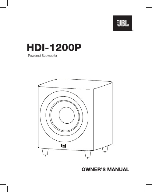
1. Do not install this equipment in a confined or building-in space such as a book case or similar unit, and remain a well ventilation conditions at open site. The ventilation should not be impeded by covering the ventilation openings with items such as newspaper, table-cloths, curtains etc.2. No naked flame sources, such as lighted candles, should be placed on the apparatus.3. The product is designed to use in moderate climates4. Voltage selector: Used to adjust the input rating (110-120 Vac/60 Hz and 220-240 Vac/50 Hz), please just insert the mains power plug into the socket-outlet with voltage within the setting of the selector. The current ratings of mains fuse links are different for different input rating (see marking for details), and the fitted mains fuse link was just related to the input rating as setting of the selector during factory assembly line work, please ask a qualified personnel to help you replace the mains fuse link before you adjust the voltage selector.5. Protective earthing terminal. The apparatus should be connected to a mains socket outlet with a protective earthing connection. In Denmark: “Apparatets stikprop skal tilsluttes en stikkontakt med jord, som giver forbindelse til stikproppens jord.” In Finland: "Laite on liitettävä suojakoskettimilla varustettuun pistorasiaan" In Norway: “Apparatet må tilkoples jordet stikkontakt” In Sweden: “Apparaten skall anslutas till jordat uttag”IMPORTANT SAFETY INSTRUCTIONSWARNING1. Only use attachments/accessories specified or provided by the manufacturer.2. To reduce the risk of fire or electric shock, do not expose this apparatus to rain or moisture.The apparatus shall not be exposed to dripping or splashing and that objects filled with liquids, such as vases, shall not be placed on apparatus.3. The mains plug is used as disconnect device, the disconnect device shall remain readily operable.TABLE OF CONTENTS....................................................................................................................................................................................1 ................................................................................................................2 3 4 ............................................................................5 ...................................................................................5 6 ..................................................................................................................................................................7 ..................................................................................................................................................7 ...........................................................................................7 ......................................................................................................7 ..................................................................................7 .....................................................................................................7 ...........................................................................................7 ..................................................................................................................7INCLUDED ITEMS ATTACHING THE GRILLE SUBWOOFER REAR-PANEL CONTROLS AND CONNECTION ...........................................PLACING THE SUBWOOFER MAKING CONNECTIONS CONNECTING TO A STEREO RECEIVER, AMPLIFIER OR PREAMPLIFIER ...................SPECIFICATIONS OPERATING THE SUBWOOFER TURNING THE SUBWOOFER ON AND OFFSUBWOOFER ADJUSTMENTS: CROSSOVER SUBWOOFER ADJUSTMENTS: VOLUMESUBWOOFER ADJUSTMENTS: PHASEABNORMAL CONDITION :LED flashing USING THE SUPPLIED CARPET SPIKESCONNECTING THE SUBWOOFER TO A TRIGGER VOLTAGE SOURCE ...................................INCLUDED ITEMSYour new JBL ® powered subwoofer incorporates a high-performance transducer and built-in amplifier that delivers the powerful, dynamic and accurate low-frequency performance that makes your filmsoundtracks and music come alive. And with adjustable crossover, phase controls and automatic turn on/off, it is also simple to connect and set up.We’re confident that this JBL subwoofer will provide every note of enjoyment that you expect – and that when you think about purchasing additional audio equipment for your home, car or office, you will once again choose JBL products.This quick-start guide contains all the information you need to set up, connect and adjust your new subwoofer. For morein-depth information, go to our web site:.Powered SubwooferTHANK YOU FOR CHOOSING THIS JBL ® PRODUCTHDI-1200P4X Note: Type of power plug varies by regions.1X1X1One combination LFE and trigger cableE n g l i s hSUBWOOFER REAR-PANEL CONTROLS AND CONNECTION1)Power Mode :When switched to 'Auto' position, the subwoofer will then be in Standby mode. It will automatically turn on when an audio signal is detected and will return to the Standby mode when no audio signal is detected after approximately 10 minutes. Setting this switch to ‘On’ keeps the subwoofer powered until Power Switch is turned 'Off.'2)On/Standby LED:When the Power Switch is in the ‘On’ position, this LED indicates whether the subwoofer is in the On or Standby state.••When the LED glows red, the subwoofer is in the Standby mode.4)Low Pass Crossover:This control determines the highest frequency at which the subwoofer reproduces sounds. The higher you set the Crossover control, the higher in frequency the subwoofer will operate and the more its bass will“overlap” that of the speakers. This adjustment helps achieve a smooth transition of bass frequencies between the subwoofer and the speakers for a variety of different rooms and subwoofer locations.5) Subwoofer Gain:Use this control to adjust the subwoofer’s volume. Turn the knobclockwise to increase the volume; turn the knob counterclock-wise to decrease the volume.6)Input Connectors:Connect these to the outputs of a stereo preamp or connect a surround processor's subwoofer output to either the left or right input. Balanced (XLR) and unbalanced (RCA) connectors are available. The inputs are 0dBV nominal to +12dBV max unbal/+18dBV max bal. The XLR input is pin 2 hot.7)Power Switch:Set this switch in the ‘On’ position to turn the subwoofer on. If you willbe away from home, or will not be using the subwoofer for an extended period, set this switch in the ‘Off’ position to conserve energy.8)Power Cord Connector:After you have made and verified the subwoofer’s input connection,plug the power cord into an active, unswitched electrical outlet for proper operation of the subwoofer.DO NOT plug the power cord into the accessory outlets found on someaudio components.3)Phase Switch:This switch determines whether the subwoofer transducer’s piston-like action moves in and out in phase with the main speakers. If thesubwoofer were to play out of phase with the main speakers, the sound waves from the main speakers could partially cancel out the sound waves from the subwoofer, reducing bass performance and sonic impact. This phenomenon depends in part on the placement of all the speakers relative to the listening position and to each other in the room.9) 12V Trigger In/Out connectors:When the subwoofer’s Power Mode Switch is set to “Trigger”, the subwoofer will automatically turn on when 5V-12V is present at the 12V Trigger “in-connection”, and will turn off when the voltage at this connection is removed. Whenever the subwoofer in on, a 12V trigger signal is available at it’s 12V Trigger Out connector. It is for use with additional HDI-1200P subwoofers, or another triggerable device.11) EQ Frequency control:Selects the center frequency of the particular problem area. The range is from 32HZ to100Hz.12) EQ Bandwidth control:Sets the range of frequencies over which the equalizer will have an effect. The range is from 0.1 octaves to 0.6 octaves; the higher the number the broader the range of frequencies that will be affected.13) EQ Level control:Allows you to adjust how much boost or cut is applied to the selected frequency by the EQ Frequency Control. This control adjusts from-12dB to a maximum of +3dB.14) EQ On/Off switch:Enables/Disables the parmetric EQ controls (Frequency, Bandwidth, and EQ Level, but not Phase)81,3412111056910) Parametric Equalization (PEQ) controls:This set of equalization controls adjust for the dominant room mode at yourlistening position in your specific listening room. The parametric equalizer includes variable controls to adjust Frequency, Bandwidth, and EQ Level of one band of frequencies. To use these controls, you must first set the EQ switch to “ON”. NOTE: Specific measurement equipment is required to properly adjust the Equalization controls. Your authorized JBL dealer can make the appropriate measurements, using suitable equipment to ensure optimal results.3When the LED glows green , the subwoofer is turned On.CONNECTING THE SUBWOOFER TO A TRIGGER VOLTAGE SOURCE12VTRIGGEROUTPUTThe subwoofer will automatically turn on if it receives a trigger voltage at its External Trigger Input connector and will enter the Standby mode when the voltage ceases.If your preamp/processor or another audio/video component has a trigger-voltage connection that supplies between 3V and 30V (AC or DC), connect it to subwoofer’s Exteranl Trigger Input connector. If the component’s trigger-voltage connection has a 3.5mm mini jack, you can use the supplied combination LFE/trigger cable to make the connection.NOTE: Do not connect the subwoofer’s External Trigger input connector to a remote control output (IR Out) of your home cinema system or surround receiver. Doing so could lead to malfunction.4PLACING THE SUBWOOFERThe performance of a subwoofer is directly related to its placement in the listening room and its physical position relative to the other speakers in the system.While it is true that in general our ears do not hear directional sounds at the lowfrequencies where subwoofers operate, when installing a subwoofer within the limited confines of a room, the reflections, standing waves and absorptions generated within the room will strongly influence the performance of any subwoofer system. As a result, the specific location of the subwoofer in the room does become important to the amount and quality of bass that is produced.For example, placing the subwoofer next to a wall generally will increase the amount of bass in the room; placing it in a corner (1) generally will maximize amount of bass in the room. However, corner placement can also increase the destructive effect of standing waves on bass performance. This effect can vary depending on the listening position – some listening positions may yield very good results while others may have far too much (or too little) bass at certain frequencies.In many rooms, placing the subwoofer along the same plane as the left and rightspeakers (2) can produce the best integration between the sound of the subwoofer and that of the left and right speakers. In some rooms, the best performance could even result from placing the subwoofer behind the listening position (3).We strongly recommend that you experiment with placement before choosing a final location for your subwoofer. One way you can determine the best location for the subwoofer is by temporarily placing it in the listening position and playing music with strong bass content. Move around to various locations in the room while the system is playing (putting your ears where the subwoofer would be placed), and listen until you find the location where the bass performance is best. Place the subwoofer in that location.MAKING CONNECTIONSCAUTION: Never make or break connections unless all system components are powered off.5CONNECTING TO A STEREO RECEIVER,AMPLIFIER OR PREAMPLIFIERIf you are connecting to a stereo device, connect the subwoofer asshown below. Stereo components rarely have subwoofer outputs. Usethem if they are available; otherwise, be sure to use a Y-connector for theleft output and one for the right output, connecting the subwoofer input toone side of each Y and the input for the left or right or right main speaker amplifierto the other side of the Y for proper main speaker operation. You can make either balanced (XLR) or unbalanced (RCA) connections between the device and the subwoofer.Using this connection method, you must set the Low Pass Crossoverknob to some frequency between 50-150Hz, NOT on the “LFE”setting.6TURNING THE SUBWOOFER ON AND OFFSet the subwoofer’s Power Switch to the ‘On’ position. Now set the subwoofer’s Power Mode to the ‘Auto’ position. The subwoofer willautomatically turn itself on when it receives an audio signal, and it will go into Standby mode after it has received no audio signal for approximately If you will not be using the subwoofer for an extended period – forinstance, if you’re going on vacation – set the Power Switch to the ‘Off’ position.SUBWOOFER ADJUSTMENTS: CROSSOVERThe Crossover control adjusts the subwoofer’s built-in low-pass filter crossover between 50Hz and 150Hz. The higher you set the Crossover control, the higher in frequency the subwoofer will operate and the more its bass will ‘overlap’ that of the speakers. This adjustment helps achieve a smooth transition of bass frequencies between the subwoofer and the speakers for a variety of different rooms and subwoofer locations.To set the Crossover control, listen for the smoothness of the bass. If the bass seems too strong at certain frequencies, try a lower Crossover control setting. If the bass seems too weak at certain frequencies, try a higher Crossover control setting.SUBWOOFER ADJUSTMENTS: VOLUMEUse the volume control to set the subwoofer’s volume. Turn the knob clockwise to increase the subwoofer’s volume; turn the knobcounterclock-wise to decrease the volume. Once you have balanced the subwoofer’s volume with that of the other speakers in your system, you shouldn’t have to change the volume control setting.Notes on Setting Subwoofer Volume:•Sometimes the ideal subwoofer volume setting for music is too loud for films, while the ideal setting for films is too quiet for music. When setting the subwoofer volume, listen to both music and films with strong bass content and find a ‘middle ground’ volume level that works for both.•If your subwoofer always seems too loud or too quiet, you may want to place it in a different location. Placing the subwoofer in a corner will tend to increase its bass output, while placing it away from any walls or corners will tend to lessen its bass output.SUBWOOFER ADJUSTMENTS: PHASEThe Phase switch determines whether the subwoofer driver’s piston-like action moves in and out in phase with the speakers. If the subwoofer were to play out of phase with the speakers, the sound waves from the speakers could partially cancel out the waves from the subwoofer, reducing bass performance and sonic impact. This phenomenon depends in part on the placement of all the speakers relative to each other and the listener(s) in the room.Although in most cases you should leave the Phase switch in the ‘Normal’ position, there is no absolutely correct setting for the Phase switch. When the subwoofer is properly in phase with the speakers, the sound will be clearer and have maximum impact, and percussive sounds like drums, piano and plucked strings will sound more life-like. The best way to set the Phase switch is to listen to music that you know well and to set the switch in the position that gives drums and other percussive sounds maximum impact.USING THE SUPPLIED CARPET SPIKESFour metal spikes are supplied for use when you place the subwoofer on a carpeted surface. Do not use these spikes when placing subwoofer on non-carpeted surfaces.To insert the spikes:1.Gently lay the subwoofer on its side (not its front or back) on a soft,nonabrasive surface.2.Screw each spike into the threaded insert in each foot. Make sure all four spikes are screwed in completely for stability.Note : NEVER drag the subwoofer to move it. Always carefully lift the subwoofer and carry it to its new location.OPERATING THE SUBWOOFERHDI-1200PMODEL DESCRIPTION ENCLOSURETYPE SPECIFICATIONS1000W RMS Powered Subwoofer CROSSOVER FREQUENCY12-inch / 300mm black paper cone, cast-frame woofers70.08lb (31.79kg)Bass-reflex design with down-firing ports COMPONENTS LF DRIVER50Hz – 150Hz (variable) 24dB/octave FREQUENCY RESPONSE28Hz - 150Hz(-6dB)POWER REQUIREMENT 100V - 240V 50/60Hz POWER CONSUMPTION (Idle/Max)Dimensions(W x D x H, grille included):Product Weight (grille iucluded):16.3″x 17.77″x 16.95″(414 x 451.3 x 430.5mm)<0.5W (standby)1180W/7.7A(max-230Vac)1230W/12.87A(max-120Vac)1190W/15.97A(max-100Vac)ABNORMAL CONDITION :LED flashing• LED flashing in red <30sec: Subwoofer is in protection mode and will recover. LED becomes green color.• LED flashing in red >30sec: Unplug/switch-off AC power till LED light off. Plug-in/switch-on AC power and subwoofer will recover. LED becomes green color.710 minutes. The subwoofer’s LED will glow green when the subwoofer is on and will glow red when the subwoofer is in Standby .E n g l i s h:JBLHDI-1200P:::::::::иа йтКEN : For additional languages, please visit FR : Pour les autres langues, veuillez visiter ES : Para obtener otros idiomas, visite DE : Informationen in weiteren Sprachen finden Sie unter RU : Если вам нужны версии на других языках, перейдите на сайт JP : 他の言語で読むには、 にアクセスしてくださいKO : 추가 언어에 대해서는 에서 확인하십시오 CHN : 如需其他语言,请访问 8HARMAN International Industries, Inc.8500 Balboa Boulevard, Northridge, CA 91329 USAPart No. 950-0564-001© 2020 HARMAN International Industries, Incorporated. All rights reserved.JBL and HDI (High Definition Imaging) are trademarks of HARMAN International Industries, Incorporated, registered in the United States and/or other countries.PolyPlas and Symmetrical Field Geometry are trademarks of HARMAN International Industries, Incorporated.Features, specifications and appearance are subject to change without notice.。

VERY IMPORTANTIn order to validate your warranty it is essential that you register it. Warranties mustbe registered onlinePlease register your warranty by visiting.au 1. IntroductionThank you for purchasing Defender 1200/1600. It is designed to provide safe and reliable power protection to your precious electronics equipment.Before you start using the product, please read this user’s manual. It contains instructions relating to safety, installation, operation maintenance and warranty. Please keep this manual in a safe place for future use.2. Safety instructionPlease read following safety instruction carefully before using Defender 1200/1600ATTENTION ! : ELECTRICAL SAFETY.●To prevent the risk of fire and electric shock, install the product in a controlledtemperature and humidity indoor area where it is free from conductivecontaminants.●To reduce the risk of overheating of the product, do not cover the cooling ventholes and avoid exposing the unit under direct sunlight or installing the unit near the heat emitting appliances such as heaters or furnaces.●Do not connect non computer related equipment such as medical equipment,life-support system, microwave oven, vaccum cleaners. Also since this unit output is not sinusoidal, please do not connect AC line filters, motors and other inductive / capacitive equipment. These equipment might damage the unit.●Do not plug the unit input cord to its own output.●Do not allow liquids or any foreign object to get inside the unit. Do not place anyliquid formed materials on the top of the unit or right next to it.●For safety purpose, proper grounding is necessary during installation of the unitin order to reduce the leakage current below 3.5mA.●Hazardous due to electric shock. Although, unit is disconnected from the mains,hazardous voltage may still be accessible through supply from the battery.Battery connection should be disconnected when servicing the product.●Do not attempt to open enclosure for modification and service, there is noserviceable parts inside the unit other than replacing the battery from front panel compartment. Modification applied to this unit void product warranty.CAUTION : BATTERY SAFETY●When replacing the batteries, use the same number and type of batteries. See.au for further information on replacement battery kit.●Do not dispose of batteries in a fire. The battery may explode. Do not open ormutilate the battery. Released electrolyte is harmful to the skin and eyes.● A battery can present a risk of electric shock and high short circuit current.●This unit contains no serviceable components other than battery. Repairing ofthe product must only be performed by qualified service personnel.●Following precautions should be observed before replacing batteries.1. Remove watches rings and other metal objects.2. Use proper tools with insulated handles.3. Do not lay tools or metal parts on the top of batteries4. Disconnect charging source prior to connecting or disconnecting batteryterminals.5. Make sure that the UPS is turned completely OFF. 3. Package ContentsYou should have received the following items inside of package:- PowerShield Defender 1200/1600VA unit- PowerShield Defender User’s Manual- USB communication cable- NetGuard CD monitoring softwareNote: Before installation, please inspect the unit and make sure that no damages have occurred during transit. If any damage is found, please notify your dealer.Please keep the shipping materials in the event the product must be returned toa repair centre for service.4. Product OverviewPowerShield Defender will protect your computer, telephone system and other electronics devices from various power disturbances including black and brown out. This product features user friendly LCD display that displays status of the product. Front View :Rear View :1. User Friendly LCD DisplaySee 6. “Understanding Display section for detail .”2. On/Off SwitchTurn on and off unit with and without utility.3. Resettable input circuit breakerBreaker will trip when there is overload / short occurs at output of the unit.Circuit breaker is rated at 10Amp.4. USB interface portConnect USB cable and computer. Install NetGuard UPS monitoring software for advanced power monitoring.5. Full time Surge protection outletsThese outlets do not provide battery backup when mains has failed. Theoutlets provide continuous protection for surges and spikes. Connectperipherals that do NOT need battery backup.UPS and Surge Protection outletsThese outlets provide battery backup power when main fails and unit isturned on.Connect peripherals that need battery backup protection. Do not connect Laser printers. 5. Installation & Start upInstall the unit in the controlled environment area that is free from dust and hasadequate air.Plug the AC input cord into the wall outlet and the unit will automatically start.NEVER Connect a laser printer / scanner to the UPS outlets. This may cause damage to the unit. The, following types equipment may cause some problems since battery output of this UPS is not sinusoidal.Inverter, Transformer, AC line filters and some PFC power supplies.6. Understanding LCD display①Input Voltage meter ②On line mode Icon○3Output voltage meter④Load level indicator○5On battery mode Icon⑥Battery level indicator7. Software Installation1. Insert NetGuard CD into CD-ROM drive and follow the on screen instruction.If Auto start does not run, then please run “ setup.exe” for the installation. 2. When the installation completed, NetGuard agent icon will appear on Taskbar.3. Once the installation is completed click plug icon found on the task bar andstart the program.8. Battery replacementDefender 1200/1600 have user replaceable battery feature. Please read warning on the front page about battery safety and follow the steps carefully shown below. Please use only PowerShield approved battery pack to maximize the performance of the unit.1. Shutdown all connected equipment and turn the UPS off by pressing on / off button.2. Remove input cord from mains and remove all output cord from the UPS.3. Flip the UPS upside down. There is a front door screw found on the front panel. Remove the screw using Philips screw driver.4. Remove the front panel by grabbing the bottom edge of the front panel forward. Remove hooks from the enclosure. Please be careful not to apply excess force to the panel as it may cause damage to the LCD cable attached to it.5. There is a metal plate holding the battery pack in the enclosure. Remove the metal plate from the unit.6. Pull tag of the battery pack and remove the battery from the unit7. Remove Red ( Positive )and Black ( Negative ) battery wires from the battery pack.8. Prepare new battery pack. Connect Black ( Negative ) wire to the new battery black terminal and connect Red ( Positive ) battery wire to the red battery terminal. Note : You will see a small spark when you connect red wire to the battery. This is normal as the unit charges energy to some component. Please check polarity of battery terminals.9. Insert the battery back into the unit and put the metal plate back to the front of the enclosure. Place the front panel and screw the battery door screw. 10. Please recharge the unit for 6 hours before you turn the unit on. 9. Trouble ShootingPlease follow the trouble shooting section below. If the problem cannot be resolved, please check PowerShield FAQ web page or call our customer support for further assistance.10. Warranty and Service.Warranty ConditionThe standard warranty is TWO (2) years from the date of purchase. The standard PowerShield procedure is to replace the original unit with a factory refurbished unit. PowerShield will ship the replacement unit once the defective unit has been received by the service department, or cross ship upon the receipt of a valid credit card number. The customer pays for shipping the defective unit to PowerShield. PowerShield pays ground freight transportation costs to ship the replacement to the customer within Australian capital cities metro areas only.WARRANTY SEVICE PROCESS :1. Review the problems discussed in the troubleshoot section of this manual toeliminate common problems.2. Verify that no input/output circuit breaker is tripped. A tripped circuit breakeris the most common problem.3. If the problem still persists, please call 1300-305-393 for technical support orfill in the form in PowerShield web page for on line technical support.Following details are needed for warranty claims.●Model number●Serial number●The date of purchase4. Be prepare to troubleshoot the problem over the phone with PowerShieldtechnical support.5. If technical support found that the product is defective, then the technicalsupport will issue a Return Material Authorization Number ( RMA # )6. If the unit is under warranty, repair is free. If not there is a repair charge.7. Pack the unit in its original packaging. Pack properly to avoid damage duringtransit. Damage sustained in transit is not covered under warranty.8. Mark the RMA # on the outside of the package.9. Return the defective unit by insured, prepaid carrier to the address given toyou by Technical support.11. Storage and MaintenanceOperationDefenders contains no user-serviceable parts other than battery pack. If the battery service life (3~5 years at 25°C ambient temperature) has been exceeded, the batteries must be replaced.Please contact your dealer or visit PowerShield web site..au/support.phpStorageBefore storing, charge the UPS 6 hours. Store the UPS covered and upright in a cool, dry location. During storage, recharge the or ship it to your dealer in the replacement battery packing12.Product SpecificationPowershield part # 990-1001 rev01PSD1600PSD12001200VA/ 720W1600VA/ 960W333312 V * 9 AH (x2)12 V * 7 AH (x2)40 min.45 min.MODEL #CAPACITY INPUTVoltage (Nominal)Voltage Range Frequency Range OUTPUT Output VoltageOutput Voltage Regulation FrequencyFrequency Range (Batt. Mode)Transfer TimeWaveform (Batt. Mode)UPS & Surge Protection Surge Protection BATTERYBattery Type & NumberBackup Time (One PC load @ 120W)Typical Recharge Time PROTECTION Full Protection Surge Protection Safety EMCOPERATING ENVIRONMENT Humidity Noise Level PHYSICALDimension D x W x H Net Weight397 x 146 x 205 mm 11.1 kg11.5kg240 Vac (Australia)177-290 Vac 50/60 Hz ± 5 Hz240 Vac (Australia)240 Vac ±10%AC mode tracks utility. Battery Mode 50 Hz ±1%50 Hz or 60 Hz ±1 Hz Typical 2 / 6 ms, 10 ms max.Simulated Sine Wave0-90% RH @ 0-40˚C (non-condensing)Less than 40 dBOverload, discharge and overcharge protection936 Joules/ 19500 AEN62040-1-1 2003, IEC60950-1 : 2001EN62040-2 20064 - 6 hours recover to 90% capacity。

附表1 2PG 辊式破碎机JB/T10245-2001附表2 2PGC齿式破碎机双齿辊破碎机JB/T11112-2010附表3 4PG(C) 四(齿)辊式破碎机JB/T11116-2010附表4 2PGCX 高效齿辊式破碎机附表5 辊式破碎机选型计算附表7 PFJ(D)煤用反击式破碎机JB/T3274-93 D为电厂J为焦煤附表9 2PF 双转子反击式破碎机JB/T2259-2005附表10 反击式破碎机选型计算附表11PE型颚式破碎机复摆颚式破碎机JB/T1388-2002附表12PEX 型颚式破碎机复摆细碎颚式破碎机JB/T3279-2005附表13 颚式破碎机选型计算附表14 PCM煤用锤式破碎机K:转子可逆用于细碎不可逆式用于中碎JB/T3765-2008附表15 PC石灰石用锤式破碎机JB/T3766-2008 K为可逆式Y为一段式不可逆式不标注附表16 PH环锤式破碎机JB/T8911-2008 Q为轻型重型不标注/带旁路槽为P,不带不标注附表17 PCD单段锤式破碎机JB/T7354-2005附表18 PCF(K)型可逆反击锤式破碎机JB/T10876-2008附表19 锤式破碎机选型计算附表20 PCL型立轴锤式破碎机JB/T10520-2005附表21 立轴式破碎机选型计算附表23 KRC系列环锤式破碎机DL/T512-931.破碎系统的计算 破碎系统要求产量计算:5432101K K K K G G K G +=G —要求破碎系统小时产量,吨/小时G 0—水泥厂熟料年产量,吨/年G 1—其他需要量,吨/年 K 1—单位熟料石灰石消耗量,吨/吨熟料K 2—石灰石全年工作天数,天K 3—石灰石破碎车间每天工作班数,K 4--石灰石破碎车间每班工作时数K 5—矿山运输不均匀系数;汽车运输取:K 5 =0.9颚式破碎机:主要优点:构造简单,管理和维修方便,工作安全可靠,适用范围广 。

MG500/1200-WD滚筒式采煤机产品说明书操作人员必须进行相应的煤矿安全规程培训使用者在使用前必须认真阅读本产品说明书太原矿山机器集团有限公司2007年2月(本产品执行MT/T81、MT/T82、Q/140000TK02-2007标准的规定)目录第一章整机概述 (1)1. 机器型号 (1)2. 机器用途 (1)3. 采煤机的组成 (1)4. 采煤机的特点 (1)5. 采煤机的技术特征 (4)第二章摇臂 (6)1. 摇臂的作用 (6)2. 规格与性能 (6)3. 机器的外形图 (7)4. 工作原理与结构特征 (7)5. 注油 (11)6. 摇臂的安装调整和试运转 (11)7. 操作规程 (12)8. 轴承目录 (13)9、常见故障的分析及处理 (14)第三章牵引传动部 (15)1. 牵引传动部的用途 (15)2. 规格与性能 (15)3. 概述 (16)4. 传动系统 (16)5. 制动器 (18)6. 轴承目录 (20)7. 冷却系统 (21)8. 润滑 (21)第四章液压调高系统 (22)1. 泵站概述 (22)2. 采煤机常见故障 (28)3. 调高油缸 (34)第五章主机架 (36)1. 结构 (36)2. 特点 (36)3. 主机架的润滑 (37)第六章辅助部件 (37)1. 喷雾冷却系统 (37)2. 辅助液压系统 (39)3. 护板及拆卸工具 (40)第七章破碎机 (41)1. 破碎机的作用 (41)2. 破碎机的主要技术参数: (41)3. 破碎机的外形、结构及工作原理 (42)4. 破碎机的润滑 (44)5. 破碎机的安装、调试和试运转 (46)6. 操作规程 (46)7. 轴承目录 (47)8. 几点说明 (47)第八章截割滚筒 (47)1. 结构与作用 (47)2. 滚筒的拆卸及注意事项 (48)第九章电气系统 (49)1. 电气系统介绍 (49)2. 电气控制系统 (60)3. 电气系统操作 (74)第十章运输、操作与检修 (76)1. 运输 (76)2. 井上检查与试运转 (78)3. 解体下井运输 (78)4. 采煤机的启动、操作和停机 (79)5. 采煤机的注油 (83)6. 采煤机的维护与检修 (84)第一章整机概述1. 机器型号MG500/1200-WD滚筒式采煤机是一种多电机驱动、横向抽屉式布置,采用机载式交流变频调速装置的新型电牵引采煤机。
All rights reserved by MEAN WELL 2021Ultra-Wide Output Range Intelligent Battery ChargerNPB-1200SeriesFrank Chen|Product Manger|Product Strategy Center******************WattPB/NPB Series RoadmapO l d G e n e r a t i o nN e w G e n e r a t i o n120 240 360 500750 1000 12001500 1700PB-120 / 230 / 300 / 360 / 600 / 1000NPB-120 / 240 / 360 / 450 / 750 / 1200/ 1700Stationary Type-Compact size programmable chargerNPBSeries Selection TableSeriesWattageAC Input VoltageDC Output VoltageBuilt-in DC FanOutput ConnectorDimension (mm)NPB-120120W 90~264Vac14.4Vdc 28.8Vdc57.6Vdc 96Vdc (450W)Terminal Block Anderson 4 pin XLR180*96*49NPB-240240W NPB-360360W NPB-450450W Terminal Block205*130*55NPB-750750W 230*158*67NPB-12001200W 250*158*67NPB-17001700W300*184*673 Key Features of NPBSeriesSmartFunctionAuto rangingRemote controlFast Charging&High Efficiency upto 93%Global certification3 years warrantySafe &DurableHighEfficiencyKey Features●Patented auto ranging with ultra-wide charging voltage(10.5~21V, 21~42V, 42~80V)●Built-in CANBus protocol for control, setting and monitoring●Programmable 2/3 stage and charging curve settings via SBP-001●Manual setting for 2/3 stage and 4 built-in charging curves via DIP switch ●Adjust charging current between 50~100% via VR on front panel●Over temperature automatic de-rating●Thermal controlled DC fan for noise reduction●Temperature compensation function to prolong battery life●Multiple protections: Short circuit / Over voltage / Over temperature /Battery under voltage / Battery reverse polarity (no damage)●Suitable for lead-acid (Pb) and li-ion batteries●Carry handle accessory available (Order No.: DS-Carry handle)●Safety: CB, UL, DEKRA, EAC, CE, UKCA(62368-1 + 60335-1/-2-29)●3-year warrantyNew Gen.Reduced Size(%)Series Dimension(LxWxH)NPB-1200250*158*67 mm-32%Old Gen.Series Dimension(LxWxH)PB-1000300*184*70 mmOld Gen. —PB SeriesNew Gen. —NPB SeriesSize MiniaturizationComparison TableOld Gen. -PB-1000SeriesOutput Power1000W1200WInput Voltage90~264Vac90~264VacCharging Voltage14.4V (stationary voltage)28.8V (stationary voltage)57.6V (stationary voltage)14.4V( 10.5~15.2V)28.8V( 21~30.4V)57.6V ( 42~60.8V)(Patent number.: CN111711254B )Patented AutoRangingAdjustable ChargingAdjust between 50~100% via VR on frontpanel or connect with computerCommunicationInterface(Built-in )Charging Stage2/3/8stage 2 or 3 stage selectable by DIP S.W or connect with PC Other Function Floating maintenance, NTC sensing , RC Floating maintenance, NTC sensing , RCEfficiency85~89% 92~94%Working Temp.-20~+60℃-30~+70℃Multi-intelligentProtectionsShort circuit / Over voltage / Over temp. /Battery reverse polarityShort circuit/ Over voltage/ Over temp./ Battery reversepolarity/ Battery static discharge protection Applicable Battery Lead-acid battery lead-acid or li-ion batteriesSafety Approvals62368-1or60335-2-29 (by series)62368-1+60335-2-29dual certificationNew Gen.-NPB-1200 SeriesAuto Ranging Charging with Multiple Functions21V 42V 80V 100V10.5V 21V 42V 54VUltra-wide charging voltage ,and can be used for a wide range of batteriesBuilt-in CANBus Protocol InterfaceWith CANBus protocol,control and monitoring function can be realized.It is helpful when users intend to modify the parameters ers can access the master and modify the parameters through CANBus,which include,ON/OFF,output voltage/current,temperature.More to that,users can even change the charging curve parameters,such as constant current level,boost voltage,float voltage and timeout function.Simple Operation InterfaceProgrammer SBP-001 is able to work with:ENC-120/240/360、HEP-1000C 、RCB/RPB-1600、DBU/DBR-3200、NPB-450/750/1200/1700 seriesSmart Programmer SBP-001Charger can be quickly connected with USB to the laptopConnectionFunction Settingcurveadjustable2 or 3-stageselectableChargingtimeout setting Programmer SBP-001 is able to work with:ENC-120/240/360、HEP-1000C、RCB/RPB-1600、DBU/DBR-3200、NPB-450/750/1200/1700 seriesLead-acid BatteriesLi-ion Batteries14.4V 、28.8V 、57.6V 、67.2V 、72V 、84V 、96V 、120V 13.8V 、27.6V 、55.2V•Wet cells •Gel cells •AGMFor A Variety of Batteries•Ternary lithium•Lithium-ion manganese oxide (LiMn 2O 4)•Lithium iron phosphate (LiFePo 4)•Electric crane •Forklift truck •Automated guided vehicle •DroneApplications•Electric drill •Electric weeder •Electric screwdriver/ Impact wrench •Electric blenderElectric Mobility•Electric motorcycle •E-Bikes •Golf cart •E-Scooters •Electric unicycleHand-held Power ToolsHandling EquipmentMobile Robotics Charging Stations•Hospital food delivery robot •Airport guide robot •Warehouse picking robot。
PL1200混凝土配料机使用说明书目录1、产品用途及特点 (1)2、主要技术参数 (1)3、结构组成与工作原理 (1)4、安装与调试 (2)5、配料系统设置 (3)6、操作维护规程及注意事项 (3)7、常见故障及排除方法 (4)1.产品用途及特点PL1200混凝土配料机是一种与搅拌机配套使用的前台自动配料设备。
它可根据用户设定的混凝土配比自动完成砂、石、水泥等三种以上物料的配料程序。
该产品依照GB10172《混凝土搅拌站技术条件》中配料系统的技术标准设计。
整机具有称量准确,配料精度高,速度快,控制功能强等特。
该产品采用电子称量,能自动进行动态零位跟踪及过冲量的自动测定和修正;数字显示,有主辅两个LED 数码显示窗,实时显示每种配料的重量和配料的累计重量;能方便的进行10种配方的保存和提取以及自动保存当前使用配方;具有完善的保护和故障诊断功能,有线遥控操作。
并且采用了分布式计算机控制,可以构成更大的控制系统。
PL1200混凝土配料机与相应的混凝土搅拌机组合,可组成各种不同形式、不同规格的组合式搅拌站,而造价仅为同规格搅拌站的1/2-1/3,且移动、安装十分方便,是生产高质量混凝土的理想设备。
PL1200混凝土配料机与双向输送皮带机配套,可供两台搅拌机配料,达到极佳的经济效果。
2.主要技术参数称量斗公称容积: 1.5m3储料斗容积:2×2.5m3生产率:60m3/h配料精度:±2%检定分度值: 2.0kg准确度等级:IIII最大称量值:2000kg可配骨料种数:3种上料高度:2300mm皮带机带速: 1.25m/s总功率:16(4×4)kw整机质量:4200kg外形尺寸:(长×宽×高)9200×2200×3000mm3.结构组成与工作原理3.1结构组成PL1200混凝土配料机由给料系统、称量系统、和微机控制系统三大部分组成。
整体结构见整机示意图。
SIMATICS7S7-1200 功能安全手册设备手册Siemens AGDigital IndustriesⓅ 10/2022 本公司保留更改的权利 Copyright © Siemens AG 2022. 保留所有权利法律资讯警告提示系统为了您的人身安全以及避免财产损失,必须注意本手册中的提示。
人身安全的提示用一个警告三角表示,仅与财产损失有关的提示不带警告三角。
警告提示根据危险等级由高到低如下表示。
危险表示如果不采取相应的小心措施,将会导致死亡或者严重的人身伤害。
警告表示如果不采取相应的小心措施,可能导致死亡或者严重的人身伤害。
小心表示如果不采取相应的小心措施,可能导致轻微的人身伤害。
注意表示如果不采取相应的小心措施,可能导致财产损失。
当出现多个危险等级的情况下,每次总是使用最高等级的警告提示。
如果在某个警告提示中带有警告可能导致人身伤害的警告三角,则可能在该警告提示中另外还附带有可能导致财产损失的警告。
合格的专业人员本文件所属的产品/系统只允许由符合各项工作要求的合格人员进行操作。
其操作必须遵照各自附带的文件说明,特别是其中的安全及警告提示。
由于具备相关培训及经验,合格人员可以察觉本产品/系统的风险,并避免可能的危险。
按规定使用 Siemens 产品请注意下列说明:警告Siemens 产品只允许用于目录和相关技术文件中规定的使用情况。
如果要使用其他公司的产品和组件,必须得到 Siemens 推荐和允许。
正确的运输、储存、组装、装配、安装、调试、操作和维护是产品安全、正常运行的前提。
必须保证允许的环境条件。
必须注意相关文件中的提示。
商标所有带有标记符号 ® 的都是 Siemens AG 的注册商标。
本印刷品中的其他符号可能是一些其他商标。
若第三方出于自身目的使用这些商标,将侵害其所有者的权利。
责任免除我们已对印刷品中所述内容与硬件和软件的一致性作过检查。
然而不排除存在偏差的可能性,因此我们不保证印刷品中所述内容与硬件和软件完全一致。
Basicline 2 PPC 1200 industrial PCUser manualUM EN BL2 PPC 12002021-02-10PHOENIX CONTACT GmbH & Co. KG • Flachsmarktstraße 8 • 32825 Blomberg • Germany4031_e n _CBasicline 2 PPC 1200 industrial PCDesignationOrder No.BL2 PPC71201-4/64-W101274012BL2 PPC101201-4/128-W101274014User manualThis user manual is valid for:UM EN BL2 PPC 1200, Revision CTable of contents4031_en_C PHOENIX CONTACT3/24Table of contents1For your safety (5)1.1Labeling of warning notes......................................................................................51.2Qualification of users.............................................................................................51.3Field of application of the product..........................................................................51.3.1Intended use ..........................................................................................51.3.2Product changes (6)2Overview and ordering data (7)2.1Description............................................................................................................72.2Ordering data (7)3Installation (9)3.1Mounting ...............................................................................................................93.2Interfaces.............................................................................................................113.2.1Power connection ................................................................................123.2.2Serial communication ..........................................................................133.3Antenna (14)A Technical appendix (15)A 1Technical data (15)BAppendixes (19)B 1List of figures...................................................................................................... 19B 2List of tables (21)BL2 PPC1201-4/…4/24PHOENIX CONTACT4031_en_CFor your safety4031_en_C PHOENIX CONTACT5/241For your safetyRead this user manual carefully and keep it for future reference.1.1Labeling of warning notes1.2Qualification of usersThe use of products described in this user manual is oriented exclusively to:–Qualified electricians or persons instructed by them. The users must be familiar with therelevant safety concepts of automation technology as well as applicable standards and other regulations.–Qualified application programmers and software engineers. The users must be familiarwith the relevant safety concepts of automation technology as well as applicable stan -dards and other regulations.1.3Field of application of the product1.3.1Intended useThe products described in this document are designed for use in manufacturing and industrial environments. They are tested to ITE levels.The products are built according to the latest safety requirements. However, dangerous situations or damage to the products or other property can arise from misuse of this device.This symbol indicates hazards that could lead to personal injury. There are three signal words indicating the severity of a potential injury.DANGERIndicates a hazard with a high risk level. If this hazardous situation is not avoided, it will result in death or serious injury.WARNINGIndicates a hazard with a medium risk level. If this hazardous situation is not avoided, it could result in death or serious injury.CAUTIONIndicates a hazard with a low risk level. If this hazardous situation is not avoided, it could result in minor or moderate injury.This symbol together with the NOTE signal word alerts the reader to a situation which may cause damage or malfunction to the device, hardware/software, or surrounding property.Here you will find additional information or detailed sources of information.BL2 PPC 1201-4/…6/24PHOENIX CONTACT 4031_en_CThe products fulfill the requirements of the EMC directives and harmonized European standards Any modifications to the systems can influence the EMC behavior. Operating display panel at full brightness for long duty cycles and/or at higher ambient temperature may short lifespan of the display.Dim panel when not in use to extend the life of the display.Radio interferenceThese products are Class A items of equipment (EN 55024 and EN 55032). When using the equipment in residential areas, it may cause radio interference. In this case, the operator is obligated to implement appropriate measures.1.3.2Product changesChanges or modifications to hardware and software of the device are not permitted.Incorrect operation or modifications to the device can endanger your safety or damage the device. Do not repair the device yourself. If the device is defective, please contact Phoenix Contact.The device contains valuable recyclable materials, which should be utilized. The electronic circuit board is fitted with a lithium battery.Dispose of the device separately from other waste, i.e., via an appropriate collection site.Overview and ordering data4031_en_C PHOENIX CONTACT7/242Overview and ordering data2.1DescriptionThe BL2 PPC 1201-4/… IPC is a configurable panel PC (PPC) that utilizes the Intel ®processors chosen for their balance of processing power, graphic performance, and energy efficiency. The robust design and I/O capability make the BL2 PPC 1201-4/… a product that can be used in a wide variety of applications. Features –Compact, rugged housing –Fanless design available–Two integrated 10/100/1000 Ethernet ports with independent MAC addresses –IP65 rating (front), IP20 rating (back)–Two UEFI-configurable RS-232/422/485 communication ports –Up to 4 GB RAM–USB 2.0 and 3.0 ports2.2Ordering dataProducts DescriptionTypeOrder No.Pcs./Pkt.Industrial panel PC , Intel ® Celeron ® processor N3350 1.10/2.40GHz, 7-inch display, 4GB of RAM, 64GB mSATA SSD, and Windows 10 IoT Enterprise LTSC 2019BL2 PPC71201-4/64-W1012740121Industrial panel PC , Intel ® Celeron ® processor N3350 1.10/2.40GHz, 10-inch display, 4GB of RAM,128GB mSATA SSD, and Windows 10 IoT Enterprise LTSC 2019BL2 PPC101201-4/128-W1012740141Accessories DescriptionType Order No.Pcs./Pkt.Visit /products for available accessories Replacement parts DescriptionTypeOrder No.Pcs./Pkt.Connector , printed circuit board connectorMC 1,5/ 2-STF-3,8118277031BL2 PPC1201-4/…8/24PHOENIX CONTACT4031_en_CInstallation4031_en_C PHOENIX CONTACT9/243InstallationWhen installing the BL2 PPC 1201-4/… in a enclosure, follow these general rules:–Verify clearances within the cabinet. Typically, leave at least 5 cm (2 in.) on each sidewith 13 cm (5 in.) on the connector side.–Drill all holes and make all cuts before beginning installation. Be sure to protect alreadyinstalled components from shavings during this procedure.–Supporting panels must be at least 1.9mm (14 ga.) to provide proper support.–Make sure that there is adequate space around the heat sink to provide sufficientcooling.3.1Mounting1.Cut a hole in the enclosure according to the dimensions for the selected display.Figure 3-1Panel cutout dimensionsNOTE:Exceeding the system temperature limits can result in performance degradation of any or all components.Install the BL2 PPC 1201-4/… with adequate clearance around the heat sink and provide a minimum of 0.5m/s air flow so that ambient air temperatures do not exceed the operation limits. Insert cooling fan(s) in the enclosure, if necessary. Connectors and switches must be accessible.Table 3-1Display cutout dimensionsDisplay sizeX (mm)Y (mm)7 in.18612410 in.229155BL2 PPC 1201-4/…10/24PHOENIX CONTACT4031_en_C2.Remove the paper seal (1) from the sticky side of the gasket (2) and apply it to the back side of the bezel (3).5.From the rear of the enclosure, place a clamp in each slot (3) and slide away from the enclosure panel.ing an alternating pattern, turn each screw clockwise until the BL2 PPC 1201-4/… is secured in the enclosure panel.7.Torque each clamp screw to 0.88 Nm.Installation3.2InterfacesFigure 3-4Connectors and ports (BL2 PPC10 1200 shown)After mounting the BL2 PPC 1201-4/… in the enclosure, make any necessary cable connections (see Figure 3-4)The available connectors are:–Ethernet (ETH): Two RJ45 connectors allow the computer to communicate on a10/100/1000 Base-T Ethernet network.–Serial (COM): Three D-SUB 9 serial ports are available for use. The default for all portsis RS -232, IIRC. Two ports are configurable as either RS -232, RS -422, or RS -485.–USB (USB): USB devices connect using Type A connectors. Two ports are USB 2.0and one is USB 3.0.1Power switch 2USB 2.0 port3Configurable RS-232/422/485 serial ports4Power connector5HDMI port6RS-232 serial port 7Ethernet RJ45 ports 8USB 3.0 connectorsUSB 3.0 ports utilize a blue connector. USB 2.0 ports are black.BL2 PPC1201-4/…1201-4/….connector to 0.5 Nm (4.4 lb f-in.). Secure the connector to the BL2 PPC1201-4/… chassis.Table3-2Power connectorPin No.Description–0 V DC+24 V DC ±20%NOTE:To ensure safe operation, use safety extra-low voltage (SELV) according to DIN EN 61131 as supply voltage.This device is protection class I item of equipment.UEFI is set to boot on power, allowing the system to boot as soon as the power plug is installed. This can be changed in the UEFI.Installation3.2.2Serial communicationTwo D-SUB 9 connectors (see Figure 3-4) can be configured to communicate on the RS -232, RS -422, or RS -485 physical layer.The BL2 PPC 1201-4/… is capable of the following communication parameters: The function of the pins in the D-SUB 9 connector varies with the different configuration settings.Table 3-3RS-232/422/485 communication settingsData bits ParityStop bits RS-2327/8None/Even/Odd 1/2RS-422/485 Autotoggle RTS 8None/Even/Odd1/2RS-422/485 Manual RTS7/8None/Even/Odd1/2The table shows the capabilities of the IPC. Configuration of parameters to communicate with a specific device is typically part of the software tool performing the communication.Table 3-4D-SUB 9 pinoutD-SUB 9 pin RS-232RS-422RS-4851DCD TXD-TXD-/RXD-2RXD TXD+TXD+/RXD+3TXD RXD+–4DTRRXD-–5GND GND GND 6DSR ––7RTS ––8CTS––9Ring indicator––BL2 PPC 1201-4/…3.3AntennaAn optional factory-installed mini PCIe card is available to allow the BL2 PPC 1201-4/… to be placed on a wireless network. Included with the installed card is an antenna (1) that attaches to a connector on the side of the unit (2).Since the BL2 PPC 1201-4/… is often installed within an enclosure, it may be advisable to install the antenna on the exterior of the enclosure rather than directly to the IPC. To do this, an appropriate length antenna cable (3) must be purchased separately.The antenna or antenna threads onto the BL2 PPC 1201-4/…. For external antennamounting, route and secure the antenna cable appropriately within the enclosure. NOTE:Do not allow metal chips to fall within the enclosure when creating the hole for mounting the antenna.Installation of the miniPCI card for wireless communication voids the UL 61010 listing.Technical appendix A Technical appendixA 1Technical dataGeneral dataOverall, dimensions (width x height x depth)* BL2 PPC71201-4/64-W10BL2 PPC101201-4/128-W10196 x 134 x 48 mm 266 x 184 x 48 mmAmbient temperature (operation)†-5 … 50°CAmbient temperature (storage/transport)-20 … 70°C Permissible humidity (relative)10% … 90%, non-condensingWeightBL2 PPC71201-4/64-W10 BL2 PPC101201-4/128-W101.2 kg2.9 kgDegree of protection IP65Mounting VESA 75, VESA 100, panel mount LED indicators*Dimensions are overall, including bezel†With 0.5 m/s airflowElectrical dataPower supply, nominal24 V DC ±20%Type of connection Removable screw-type Conductor size0.2 … 2.5 mm² (24 … 12 AWG) Torque, wire clamping screw0.5 … 0.6 NmCurrent and power data*Current consumption @ 24 V, maximum†BL2 PPC71201-4/64-W10BL2 PPC101201-4/128-W101.07 A 1.09 APower, maximum @ 24 V, maximum†BL2 PPC71201-4/64-W10BL2 PPC101201-4/128-W1025.7 W26.0 W*Does not include wireless mini PCIe card†Windows 10, SSD and M.2 drives, 8 GB RAM, loopback plugs in all COM and LAN ports, USB ports fully loaded, running Burn-in® tests Operating systemsOperating system (configuration option)Windows® 10 IoT Enterprise LTSB 2019Data storageType (configurable option)Internal mSATA SSDNumber of bays1RAID support NoneBL2 PPC1200Main memoryRAM, maximum 4 GBType DDR3LProcessor dataProcessor Intel Celeron N3350Clock speed 1.10 GHz2.40 GHz burstCache 2 MBNumber of cores2Number of threads2Maximum TDP 6 WNumber of memory channels2InterfacesUSB1x Type A USB 2.0; 2x Type A USB 3.0Serial connection1x D-SUB 9 (male), UEFI selectable for RS-232/422/485 Super I/O chipset Nuvoton NCT6106DChipset IntegratedVideo out1x DP++Graphic processor Intel HD Graphics 500Number of Ethernet connectors2Ethernet connection10/100/1000 MbpsLAN chipset Intel Ethernet controller I211-ATNumber of mini PCIe slots*1Mini PCIe card size, maximum30.00 x 50.95 x 15.00 mm*This slot is not available if ordered with the wireless optionTechnical data Radio module (configurable)Connector type Mini PCIeDevice interface PCI Express v1.2Frequency band IEEE 802.11 a/b/g/nAntenna impedance50Frequency range 2.4 GHz5 GHz 2412 ... 2472 Hz 5180 ... 5825 HzData transfer rate 2.4 GHz5 GHz 802.11b/g 1… 54 Mbps802.11a 6 … 54 Mbps802.11n 2.4/5 GHz MCS0/8 … 7/13Transmit power, typical 2.4 GHz (b)2.4 GHz (g)5 GHz (a)12.5 dBm (Channel 1)14.5 dBm (Channel 2-10)11.0 dBm (Channel 11)13.5 dBm (Channel 1)14.0 dBm (Channel 2-10, 54 Mbps)11.5 dBm (Channel 11)12.5 dBm (Channel 36-165, 6-48 Mbps) 12.0 dBm (Channel 36-165, 54 Mbps)Display – 7 in. (BL2 PPC71201-4/64-W10)Display backlighting type LEDScreen size, diagonal178 mmScreen size, horizontal x vertical153.6 x 90 mm Resolution1024 x 600Type Capacitive touch screen Brightness320 Cd/m²Number of colors16.2 million Backlight life, minimum20000 h Contrast ratio1000:1View angle, horizontal/vertical (CR=10), typ.140°/120 Installation cutout dimensions (width x height)186 x 124 mmBL2 PPC1200Display – 10 in. (BL2 PPC101201-4/128-W10)Display backlighting type LEDScreen size, diagonal256 mmScreen size, horizontal x vertical217 x 136 mm Resolution1280 x 800Type Capacitive touch screen Brightness400 Cd/m²Number of colors265,000 Backlight life, minimum25000 h Contrast ratio1300:1View angle, horizontal/vertical (CR=10), typ.170°/170°Installation cutout dimensions (width x height)229 x 155 mm Mechanical testsShock test according to IEC 60068-2-2720g with 11 ms duration Vibration resistance according to EN 60068-2-63g, 5-500 Hz ApprovalsCE compliantFCC Part 15 Class AUL/cUL UL 61010* *Installation of the miniPCI card for wireless communication voids the UL 61010 listing.Use of the VESA mount (outside an enclosure) removes the UL 61010 listingAppendixes B AppendixesB 1List of figuresSection 3Figure3-1:Panel cutout dimensions (9)Figure3-2:Gasket installation (10)Figure3-3:Panel-mounting clamps (10)Figure3-4:Connectors and ports (BL2 PPC10 1200 shown) (11)Figure3-5:Power connector (12)Figure3-6:Antenna installation (14)BL2 PPC1200List of tablesB 2List of tablesSection 3Table3-1:Display cutout dimensions (9)Table3-2:Power connector (12)Table3-3:RS-232/422/485 communication settings (13)Table3-4:D-SUB 9 pinout (13)4031_en_C PHOENIX CONTACT21/24BL2 PPC120022/24PHOENIX CONTACT4031_en_CPlease observe the following notesGeneral terms and conditions of use for technical documentationPhoenix Contact reserves the right to alter, correct, and/or improve the technical documentation and the products described in the technical documentation at its own discretion and without giving prior notice, insofar as this is reasonable for the user. The same applies to any technical changes that serve the purpose of technical progress. The receipt of technical documentation (in particular user documentation) does not constitute any further duty on the part of Phoenix Contact to furnish information on modifications to products and/or technical documentation. You are responsible to verify the suitability and intended use of the products in your specific application, in particular with regard to observing the applicable standards and regulations. All information made available in the technical data is supplied without any accompanying guarantee, whether expressly mentioned, implied or tacitly assumed.In general, the provisions of the current standard Terms and Conditions of Phoenix Contact apply exclusively, in particular as concerns any warranty liability.This manual, including all illustrations contained herein, is copyright protected. Any changes to the contents or the publication of extracts of this document is prohibited. Phoenix Contact reserves the right to register its own intellectual property rights for the product identifications of Phoenix Contact products that are used here. Registration of such intellectual property rights by third parties is prohibited.Other product identifications may be afforded legal protection, even where they may not be indicated as such.PHOENIX CONTACT23/24How to contact usInternet Up-to-date information on Phoenix Contact products and our Terms and Conditions can befound on the Internet at:Make sure you always use the latest documentation.It can be downloaded at:/productsSubsidiaries If there are any problems that cannot be solved using the documentation, please contactyour Phoenix Contact subsidiary.Subsidiary contact information is available at .Published by PHOENIX CONTACT GmbH & Co. KGFlachsmarktstraße 832825 BlombergGERMANYPHOENIX CONTACT Development and Manufacturing, Inc.586 Fulling Mill RoadMiddletown, PA 17057USAShould you have any suggestions or recommendations for improvement of the contents andlayout of our manuals, please send your comments to:*************************24/24PHOENIX CONTACT GmbH & Co. KG • Flachsmarktstraße 8 • 32825 Blomberg • Germany。