cc1
- 格式:doc
- 大小:106.50 KB
- 文档页数:8
电缆充电电流开合试验cc1和cc2
充电cc1和cc2
(cc1):充电过程中,非车载充电设备通过连接确认触头的输入电压信号进行不间断监测充电插头和充电插座连接状态,一旦出现异常,非车载充电设备立即关闭直流电源输出,在完成卸载后,断开开关S1。
(cc2):充电过程中,如果100ms内非车载充电设备没有收到电池管理系统周期发送的充电级别需求报文,非车载充电设备也响应关闭直流电源输出的功能。
100ms=0.1秒
ms表示毫秒。
1毫秒=0.001秒,1秒=1000毫秒。
100÷1000=0.1(秒),所以100ms=0.1秒
所以本题正确的写法应是100ms=0.1s,或100毫秒=0.1秒。

typec6针母座的针脚定义
Type-C 6针母座的针脚定义
Type-C是一种用于连接电子设备的通用接口标准,而Type-C 6针母座是其中一种常见的连接插座。
它具有6个针脚,每个针脚承担着特定的功能,下面是Type-C 6针母座的针脚定义:
1. VBUS (电源线):这个针脚用于传输电源,可以为其他设备提供电力供应。
2. GND (接地线):GND标志着接地线,用于连接设备的地线,确保电路的稳定性。
3. CC1 (通信信道1):CC1是用于数据通信和识别连接设备的信道,它可以识别附加到Type-C接口的设备类型,如计算机、手机等。
4. CC2 (通信信道2):与CC1类似,CC2也是用于数据通信和识别连接设备的信道。
5. D+ (数据传输线正极):D+是用于传输正向数据的线路,如音频、视频等。
6. D- (数据传输线负极):D-是用于传输负向数据的线路。
这些针脚相互配合,使得Type-C 6针母座能够实现电源供应、数据传输和设备识别等功能。
(Type-C的详细资料可参阅相关技术文档,此处不提供网址链接)。
总结一下,Type-C 6针母座的针脚定义包括VBUS,GND,CC1,CC2,D+和D-,它们合作使得设备之间可以进行电源供应和数据传输,并且能够识别连接的设备类型。
这种接口标准的普及,为消费者提供了更灵活、便捷的连接解决方案。

cc1.exe 用法-回复cc1.exe 是一个Windows 操作系统上的命令行编译器,用于将C 语言源文件编译为可执行文件。
在本文中,我们将详细介绍cc1.exe 的用法,以及一步一步的回答常见问题。
首先,为了使用cc1.exe,我们需要确保它已经安装在我们的计算机上。
cc1.exe 是GNU 编译器集合中的一部分,通常可以在MinGW 或Cygwin 这样的开发环境中找到。
安装完相应的开发环境后,我们就可以开始使用cc1.exe 进行编译了。
1. 打开命令提示符或者终端窗口。
在Windows 上,我们可以通过按下Win + R 键,然后输入"cmd" 打开命令提示符。
在Linux 或macOS 上,我们可以在启动器中找到终端应用程序。
2. 确定cc1.exe 的路径。
在命令提示符或终端中,输入"where cc1"(Windows)或者"which cc1"(Linux/macOS),然后按下回车键。
系统将返回cc1.exe 可执行文件的完整路径。
3. 切换到源代码文件所在的目录。
在命令提示符或终端中,我们需要使用"cd" 命令切换到存放C 语言源文件的目录。
例如,如果源代码文件位于"C:\myproject" 目录下,则输入"cd C:\myproject",然后按下回车键。
4. 使用cc1.exe 进行编译。
一旦在源代码文件所在的目录中,我们就可以使用cc1.exe 进行编译了。
在命令提示符或终端中,输入"cc1 [源文件名].c",然后按下回车键。
5. 检查编译结果。
cc1.exe 在成功编译源文件后,将生成一个默认的可执行文件,文件名与源文件名相同,只是后缀名改为".exe"。
我们可以通过在命令提示符或终端中输入"[源文件名].exe" 来运行该可执行文件。

typec接口cc脚工作原理
Type-C接口的CC脚(Connection Configuration)是用于检测和识别连接设备的一组引脚。
CC脚有两个:CC1和CC2,分别用于发送和接收信号。
当两个设备连接时,它们会互相发送探测信号并进行握手操作,以便识别连接的设备类型和角色。
CC1和CC2可以承载的信号包括两种:初始VBus电压(5V或12V)和Type-C协议。
连接双方通过协商确定一方扮演Source角色,即提供电源或Sink角色,即消耗电源。
Source角色提供的电源通过VBus 引脚输出给Sink角色。
在协商角色和电压之前,连接双方会进行初步探测,例如识别连接的设备类型和确定通信速率等。
这些操作通过CC引脚发送和接收电压来实现。
当设备连接时,Type-C接口会先发送5V的电压,如果连接的设备是支持Type-C协议的设备,则会返回应答信号并进行进一步的握手协商。
如果连接的设备不支持Type-C协议,则会继续使用5V电源供电,而不进行任何握手操作。
总之,Type-C接口的CC脚通过发送和接收信号,实现设备类型识别、电压协商、角色切换等操作,为连接设备提供了更智能化和高效的数据传输方式。
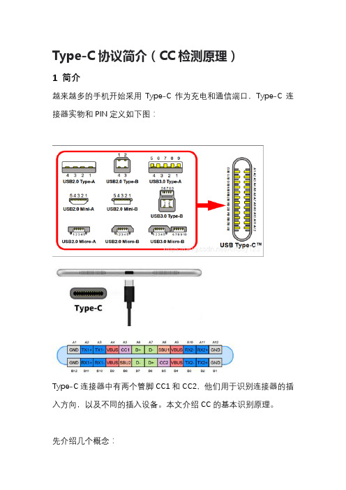
Type-C协议简介(CC检测原理)1 简介越来越多的手机开始采用Type-C作为充电和通信端口,Type-C连接器实物和PIN定义如下图:Type-C连接器中有两个管脚CC1和CC2,他们用于识别连接器的插入方向,以及不同的插入设备。
本文介绍CC的基本识别原理。
先介绍几个概念:DFP——Downstream Facing Port,也就是Host UFP——Upstream Facing Port,也就是DeviceDRP——Dual Role port,既可以做DFP,也可以做UFP。
在建立连接之前,DRP的角色在DFP和UPF之间切换。
如果两个DRP 连接,最先随机到那种角色后开始建立连接,之后可以通过USB协议协商进行动态切换。
2 为什需要CC检测虽然USB Type-C插座和插头的两排管脚对称,USB数据信号都有两组重复的通道,但主控芯片通常只有一组TX/RX和D+/-通道(某些芯片有两组TX/RX和D+/-通道)。
由于USB2.0的数据率最高只有480Mbps, 可以不考虑信号走线的阻抗连续性,USB2.0的D+/-信号可以不被MUX控制而直接从主控芯片走线,然后一分二连接至USB Type-C插座的两组D+/-管脚上。
但USB3.0或者USB3.1的数据率高达5Gbps或者10Gbps,如果信号线还是被简单地一分二的话,不连续的信号线阻抗将严重破坏数据传输质量,因此必须由MUX切换来保证信号路径阻抗的一致性,以确保信号传输质量。
下图中右侧所示的MUX从TX1/RX1和TX2/RX2中选择一路连接至主控芯片,而这个MUX就必须被CC管脚控制。
在USB2.0应用中,无需考虑CC方向检测问题,但USB3.0或者USB3.1应用中,必须考虑CC方向检测问题。
注意UFP,比如U盘,移动硬盘内部不需要CC逻辑检测,因为它是上行,只有一对USB2.0或USB3.0信号,如下图3 CC检测原理CC信号有两根线,CC1和CC2,大部分USB线(不带芯片的线缆)里面只有一根CC线,DFP可根据两根CC线上的电压,判断是否已经插入设备。

一、typec接口的介绍Type-C接口是一种新型的通用接口,它可以同时传输数据、视瓶和电源信号。
它的设计目标是取代传统的USB接口,成为未来各类电子设备的标准接口。
Type-C接口采用了倒插式设计,可以随意放置插头,无需关心插入的方向。
它还支持高速数据传输和快速充电功能,具有较强的通用性和扩展性。
二、Type-C接口中CC1和CC2的作用CC1和CC2(Configuration Channel)是Type-C接口中的两个通信信道,它们负责在设备之间进行通信和协商通信协议。
在Type-C 接口中,CC1和CC2通常被用于实现插头的翻转检测和电源传输的协商过程。
通过CC1和CC2通道的连接方式,设备可以进行插头的正确识别和通信协议的选择,从而实现电源传输和数据传输的正常进行。
三、CC1和CC2的波形在Type-C接口中,CC1和CC2通道的波形特征对于插头的翻转检测和电源传输协商至关重要。
一般情况下,CC1和CC2通道的波形包括以下几种情况:1. 非连接状态下的波形:当Type-C接口的插头未连接时,CC1和CC2通道通常会呈现出开路状态的波形,即电压水平为0V。
2. 连接状态下的波形-1:当插头插入Type-C接口并未完成翻转时,CC1和CC2通道通常会呈现出保持电平的波形,电压水平可以是0V 或者V(RA)。
3. 连接状态下的波形-2:当插头插入Type-C接口并完成翻转后,CC1和CC2通道通常会呈现出交替变化的波形,即电压水平会在0V 和V(RA)之间进行反复切换,以完成插头的正确识别和协商通信协议的选择。
四、CC1和CC2波形的重要性CC1和CC2通道的波形特征对于Type-C接口的正常使用至关重要。
通过对CC1和CC2波形的检测和分析,可以实现插头的正确翻转检测和电源传输协商。
一旦CC1和CC2通道出现波形异常,就可能导致插头识别失败、电源传输不稳定甚至损坏设备的情况发生。
工程师需要对CC1和CC2波形进行详细的测试和分析,以确保Type-C接口在使用过程中的稳定性和可靠性。
Multi-function CCTV control keyboardESD-CC1Users’ ManualVersion 3.0Table Of Contents1. General Introduction (4)2. Front Panel & Real Panel (5)2.1 Front Panel (5)2.2 Rear Connector Panel (6)2.3 Switch setting on rear connector PCB (6)3. Installation (7)3.1 RS485 cable (7)3.2 Cable connections (7)4. Operations (8)4.1 Power On (8)4.2 Camera Control Mode (8)4.2.1 OSD Camera Setting (9)4.2.2 Joystick (9)4.2.3 Set Preset and Run Preset (9)4.2.4 Sequence setting and execution (9)4.2.5 Auto-Pan (10)4.2.6 Cruise (11)4.2.7 Zoom/Focus Lens Control (12)4.2.8 Camera settings (All camera settings)……………………………………………12-154.3 System Setting Mode (15)4.3.1 System Linking (16)4.3.2 Set Keyboard ID (16)4.3.3 System Monitor Setting (16)4.3.4 RS-232 Baud Rate Setting (17)4.3.5 Date Setting (17)4.3.6 Time Setting (17)4.3.7 System Date/Time Correction (18)4.3.8 System Alarm List (18)4.3.9 Camera Type & Class (18)4.3.10 Key Press Beep (19)4.3.11 Alarm Reaction (19)4.3.12 Password Set (19)4.4 Multiplexer Control (19)4.5 The control and setting of Video Matrix Switcher (19)5. Troubleshooting (20)Appendix A. RS485 Communication (21)A.1 Connector (RJ-11 6P6C) (21)A.2 ID Address Mapping (21)Appendix B. Technical Specifications (22)Appendix C. The Architecture of SuperMPX and SuperMMX.......................................23-24 Appendix D. Commands Tree of Operating and Setting...............................................25-26 Appendix E. Software upgrade. (27)1. General IntroductionThis control keyboard is 100% integrated with our full range CCTV series, or other products that are compatible with the DSCP protocol. Equipped with the most sophisticated control protocols, this high-tech keyboard will greatly enhance the efficiency of the overall CCTV system. It also effectively integrates our Triplex Multiplexer, High Speed Dome Camera and other CCTV devices into one powerful yet user-friendly solution.Developed with the most advance data communication protocol-DSCP, this control keyboard is able to automatically detect peripheral devices for their model and capability. Together with advanced system integrating technology and user-friendly design, it provides real-time operating environment for monitoring and controlling in a multiple devices surveillance system.42. Front Panel & Real Panel2.1 Front panel1. Multiplexer mode.2. Matrix mode.(Reserved)3. Camera/Dome mode.4. System Setup key.5. Camera Function keys and Direction keys.6. Camera Menu key /Enter key: in Camera Control mode, press for 2 seconds will get OSD menu. In Camera Setup mode it functions as Enter key.7. LCD panel: display system status and set up dialogue. In power saving mode, the LCD backlight will be temporarily turned off (50% power saved). Simply press any key to exit power saving mode.8. Keyboard Lock (keep pressing for 3 seconds to lock/unlock the keyboard).9. Joystick10. Multiplexer or Matrix control keys.11. VCR remote keys with blue.12. Home key.13. Number keys and ENTER key.14. Function key. F1 is remote-reset function. F2 is lock/unlock device function. F3 is reservedcurrently. F4 is Dome speed test function.15.Lens control keys.16.Sequence setting keys including INS/DEL/ENDSEQ keys.S4 RS232 Control N ▓ V Normal (Default, DTR/DSR function) N ▓ V VCR control (RTS/CTS function)3. InstallationMonitor• Dome/CameraConnect the RS-485 cables from cameras to keyboard. And connect the video cables to monitor or multiplexer.(Caution! The ID address and video channel connection (of multiplexer) must follow the definition in Appendix A!)• Video MultiplexerConnect RS-485 to the keyboard directly or loop through the cameras.74. Operations4.1 Power OnAfter connecting all necessary cables, turn on the peripheral devices, and then connect DC12V adapter to the keyboard. The LCD will display the following message:Later, the keyboard will enter ‘Stand By Mode ’.Stand By Mode:In the 'Stand By Mode', user can enter ‘System Setting Mode ’ by pressing “SYS” key (section 3.4), or enter ‘CameraControl Mode ’ by pressing Camera Select key (section 3.5), or enter ‘Multiplexer Control Mode ’ by pressing Multiplexer Select key (section 3.6), or enter ‘Matrix Control Mode ’ by pressing Matrix Select key MX (section 3.7).4.2 Camera Control ModeWhen the keyboard is in Stand By Mode , you can select any active camera by pressing Camera Select key, number key "1"~"223" and then “ENTER” key or press # + 1(~9) to choose the index X camera of class X . The ID and device type of the selected camera will be displayed on LCD. P=Pan, T=Tilt, Z=Zoom, F=Focus, OSD=OSD available.Now the keyboard is in Camera Control Mode , you can control all of the camera’s functions in this mode.8Camera Control Mode:The second row on the LCD allows users to input number 1~255, it’s used to specify preset point or the other cameraparameters. Detail operation will be described in the following sections. Please refer to camera’s manual to understand the function of each camera. 4.2.1 OSD camera settingIf the camera selected is equipped with OSD function, you can press “CAMERA MENU” key to get the OSD menu on the monitor. Then you can use the four direction keys to setup the parameters of the camera. 4.2.2 JoystickThe joystick is used to control Speed Dome Camera viewpoint (Pan/Tilt position). Normally, the Speed Dome Camera supports hemispheric viewpoints (Pan 360° and Tilt 90°). The speed of the dome movement depends on the angel of the Joystick, the more you push the Joystick, the faster the dome will move. The maximum speed when using Joystick is limited to get better control of the dome camera, there are 7 different speeds available. 4.2.3 Set Preset and Run PresetUnder the Camera Control Mode , you can key in a number (1~128) and press “SET PRESET” key, the keyboard will ask the dome to store current position as a ‘Preset’. You may also key in the number and press “GO PRESET” key to ask the dome to move to that specific preset point.Camera Control Mode4.2.4 Sequence setting and executionThe dome camera allows you to program up to four sequences, each sequence contains 32 steps. When the keyboard is under the Camera Control Mode , you may input number 1~ 4, and press “RUN SEQ” key. The dome will start touring that sequence, and show the following message on the LCD for a few seconds:You can also input number 1~ 4 and press "SET SEQ" key to edit the sequence contents. You may use "▲"/"▼" keys to scroll through all 32 steps, and use "◄"/"►" keys to move the cursor to the items you want to edit.9A. The first three digit (xxx) indicate the step number.B. PST means ‘Preset Point’, it is the preset point used for this step, range from 1 to 128.C. SPD means ‘Speed’, it defines how fast the dome will move from previous step to this step, the number range from1 to 15.D. DWELL means the dwell time of this step. The number range from 1 to 127, and the unit is second.If you want to insert a step in the sequence, you can press “INS” key, then key in the parameters in current position. If you want to delete a step in the sequence, just press “DEL” key, current step will be erased immediately.After sequence editing is finished, you may use “ESC” or "ENDSEQ" keys to exit. The difference between these two keys is: pressing “ENDSEQ” will delete the steps behind current step; pressing “ESC” will keep every step effective. 4.2.5 Auto-PanUnder Camera Control Mode , you can press “AUTOPAN” key to enter Auto Pan mode , the LCD will display:Auto Pan mode:Press "1", the dome start to pan automatically, and the LCD will display:Press "2" allows you to edit the route of auto-pan. You have to move the dome to the start point, and press “Enter” key to confirm.Then move the dome to the end point and press “Enter” key to confirm.10And then you have to decide the pan direction and the pan speed:4.2.6 CruiseUnder Camera Control Mode , you can press “CRUISE” key to enter Cruise mode , the LCD will display:Cruise mode:Press "1", the dome starts to cruise automatically, and the LCD will display:Press "2" allows you to edit the route of cruise. You have to move the dome to the start point, and press “Select Device/ Enter” key to confirm.11Then move the dome to the end point and press “Select Device/ Enter” key to confirm.And then you have to press “Select Device/ Enter” key to save it.4.2.7 Zoom/Focus Lens controlIn the ‘Camera Control mode ’, you can control the lens using the ‘Lens Control Keys’ on the right hand side of the keyboard. These function keys include Zoom Wide/Tele, Focus Near/Far and Iris Open/Close and Auto Focus hot key.4.2.8 Camera settingPressing ”SETUP” key in Camera Control Mode will enter Camera Setting Mode , you can setup many features of the camera here. You have to key in the password first:Camera Setting ModeAfter you key in the correct password, you can use the "▲"/"▼" keys to scroll through these setup pages, and use "◄"/"►" keys to change the setting. Use “ESC” key to exit after the configuration is finished.4.2.8.1 Auto Turn-AroundThe Auto Turn-Around function is useful for following a person who passes directly beneath the camera, the dome rotates 180 degrees if you keep holding the joystick. Menu 2.1 allows you to enable or disable this function.Fig.4.2.6.5124.2.8.2 Zoom speed settingThis item allows you to change the speed of zoom lens movement, use "◄"/"►" keys to select Slow or Fast speed.4.2.8.3 Digital Zoom ratioThis item allows you to change the digital zoom ratio from OFF (no digital magnify) to 8X (8 times digital magnify).4.2.8.4 Alarm SetupThe dome camera is equipped with four alarm input connectors, Alarm1~Alarm4. Once the alarm signal is detected, the dome camera will move to a preset viewpoint automatically. Menu 2.4 allows you to decide how the dome will react to the alarm inputs.Menu 2.4.1 decide how long the dome camera will stay in the alarm preset. This parameter is common for all the four alarm inputs.13Menu 2.4.2 is the entry point for parameters related to Alarm1 input: ON/OFF (detect alarm signal or not), NC/NO (alarm signal type) and correspondent preset point for each Alarm input:4.2.8.5 Speed by ZoomWhen the lens is in Tele position, the pan/tilt speed is better slowed down to allow the user to trace the target smoothly. If you select ON here, the Pan/Tilt movement of the Dome will be proportional to the zoom ratio.4.2.8.6 Set PAN bias144.2.8.7 Set TILT bias4.2.8.8 Check Camera VersionThis item shows you the hardware and software version of the dome camera, it may be an useful information when you’re checking with the installer for trouble shooting.4.2.8.9 Auto Save Function.The user can disable or specify the duration time of 1~42 minutes to make a power-up default preset point for dome camera to go back after the operator stops moving the dome.4.2.8.10 Line Lock Phase Adjust Function.User should not use this function for detailed adjustment of camera module.4.2.8.11 Receiver Auxiliary Switch Function.Users can press 1 or 2 to select one of two receiver auxiliary switches and then press "◄" / "►" key to turn on/off receiver auxiliary switch.4.3 System Setting ModeIf you press the “SYS” key and enter the correct password (default password is 0000), the keyboard will enter ‘System Setting Mode ’. Detail description of each item will be discussed in the following sections. Please use "▲" and "▼" keys to scroll through these setup pages.15System Setting Mode:4.3.1 System LinkingMenu 1.1 allow you to search for active cameras on the RS485 control bus again, press "◄" or "►" key to start searching.4.3.2 Set Keyboard IDMenu 1.2 allow you to set up the ID number of this keyboard, use "◄" or "►" key to change the number. The default ID is 000, if there are more than one keyboard in the same system, they must have different ID address to avoid communication conflict.4.3.3 System monitor settingWhen you use the keyboard to control devices, it needs Monitor to see the image to prevent wrong actions. There are four sources you can select, the first one is Multiplexer’s main monitor output, the second one is Matrix’s output, the third one is the SuperMPX mode, and the last one is SuperMMX mode.When you select Item a.(as Fig.4.3.3.1), the image of camera will be displayed on Multiplexer’s main monitor. On the other hand, when select Item b. (as Fig.4.3.3.2 and hit “ENTER”), please input the Output Channel/Monitor no. (as Fig.4.3.3.5) and hit “ENTER” key. The image of camera will be displayed on Matrix’s monitor. Hit “ESC” to go back System mode.Please refer Appendix C to see the architecture of SuperMPX and SuperMMX.164.3.4 RS-232 Baud rate settingTo select Item 4 (as Fig.4.3.4.1) and you can set RS232 Baud rate. The RS-232 protocol of keyboard is the standard 8,N,1. It provides three Baud rate setting (9600 (default), 4800 and 2400 bps). It can be set on your request (as Fig.4.3.4.1,4.3.4.2, 4.3.4.3). Hit "◄"/"►" key to select baud rate and hit “ENTER” key). Hit “ESC” to go back System mode.4.3.5 Date SettingSelect Item 5(as Fig.4.3.5.1) and hit “ENTER” key (as Fig.4.3.5.2), then you can set the correct date of keyboard. Please hit "◄"/"►" key to select items (year, month and date) and input the correct numbers. The default date is local. Hit “ESC” to go back System mode.4.3.6 Time SettingSelect Item 5(as Fig.4.3.6.1) and hit “ENTER” key (as Fig.4.3.6.2), then you can set the correct time of keyboard. Please hit "◄"/"►" key to select items (hour, minute and second) and input the correct numbers. The default date is local. Hit “ESC” to go back System mode.174.3.7 System Date/Time CorrectionSelect Item 8(as Fig.4.3.7.1) and hit “ENTER” key (as Fig.4.3.7.2), then you can adjust all the devices at same time. Before you adjust the system date/time. Please check the date/time of this keyboard and make sure it’s correct. Hit “ESC” to go back System mode.4.3.8 System Alarm ListRecord the latest 10 Alarm information of the system bus.4.3.9 Camera Type & ClassThis item allows you to assign protocol type for each camera in current group number. Use "◄" or "►" key to change the setting , “▲” or “▼” key to choose the index and “AUTOPAN” or “CRUISE” key to choose the class.184.3.10 Key Press BeepThe built-in buzzer will beep when the user press any valid key, this item allow you to turn the beep on or off. Use "◄" or "►" key to change the setting.4.3.11 Alarm ReactionWhen the alarm input of the dome camera is triggered, the camera will send an alarm message to the keyboard. The keyboard can be programmed to react to the message by: 1. Buzzer beep, 2. link to that camera automatically (so operator can control that camera immediately), 3. switch the multiplexer to that channel in full screen.These reactions are disabled (OFF) by default. Menu 1.5 allows you to enable (ON) this function. Use "◄" or "►" key to change the setting.4.3.12 Password SetThis item allows you to change the password, you have to enter the same number twice to confirm the change.4.4 Multiplexer Control Under any mode, hit Multiplexer control key and input the Multiplexer’s number then hit “ENTER” key (as Fig.4.4.1). Then, you can remotely control that particular Multiplexer. Please refer Multiplexer’s manual to get the method of control and setting.4.5 The control and setting of Video Matrix SwitcherIt is reserved now.Under any mode, you can hit “Matrix” hot key to remote control the video matrix switcher. You can hit “ENTER” key to enter OSD control mode. You can hit “Direction”, “ENTER” and “ESC” keys to set all programs of Matrix. Please reference the Matrix’s manual to get the detail definition of Matrix.195. TroubleshootingWhen you get trouble with using the keyboard, please follow the procedures below to isolate the problem before call back to the installer.A. Nothing or wrong text is displayed on LCD.Possible causes and countermeasures:a. No power or unstable power source: check the output of the DC12V adapter is correct or not.b. Interference comes from peripheral devices: disconnect the RS-485/422 and RS-232 connectors and re-start thekeyboard. If the keyboard works fine now, then we can conclude some of the other device cause the trouble, please connect the installer to solve the problem.B. Device Link-up problemPossible cause and treatment:a. The keyboard RS-485 cable connection is not secure: please make sure the cable is firmly connected on both thekeyboard side and device side.b. Wrong start-up procedure: some peripheral devices (as P/T/Z/F dome cameras) need longer initial time afterpower on. They can not recognize the linking command during the initial time. Please make sure that all the peripheral devices have been powered-up before applying power on the keyboard.c. RS-485 cable open or short: please separate each device and find out which segment of the communication youcan connect single keyboard and device to confirm this possible cause. Please connect the concerning people and tell them this test result.C. One or some devices lose controlPossible cause and treatment:a. The bus does not connect to those peripheral devices: please check the RS-485 cables on those peripheral sidesand make sure those cables are connected perfectly.b. Malfunction of the peripheral devices: you can connect one keyboard to one device to confirm the properfunctioning of the device.c. One of the RS-485 cable segments open or short circuit: disconnect the cable segment and locate the failuresegment. Please connect the installer for support.20B. Multiplexer (MPX) Channels and Camera ID MappingMPX # MPX ID Camera ID Remark1 E0H,224 01H – 10H\ 1~16 Map to channel 1~16 of MPX2 E1H,225 11H – 20H\ 17~323 E2H,226 21H – 30H\ 33~484 E3H,227 31H – 40H\ 49~645 E4H,228 41H – 50H\ 65~806 E5H,229 51H – 60H\ 81~967 E6H,230 61H – 70H\ 97~1128 E7H,231 71H – 80H\ 113~1289 E8H,232 81H – 90H\ 129~14410 E9H,233 91H – A0H\ 145~16011 EAH,234 A1H – B0H\ 161~17612 EBH,235 B1H – C0H\ 177~19213 ECH,236 C1H – D0H\ 193~20814 EDH,237 D0H – DFH\ 209~223 Only 15 Dome can be connect15 EEH,238 None Can connect to normal camera16 EFH,239 None Can connect to normal camera21Appendix B. Technical SpecificationsThe list is the specifications of CCTV control keyboard, our company reserve the right to modify the specifications.Item DescriptionCameraSpeed Dome Camera all functionSystem ControlOSD Camera all functionZoom Lens Camera all functionVideo Multiplexer All functionVideo Matrix (reserved)Linking capability 255 Devices(Maximum)RS232Signal RS485(half-duplex),ConnectorsPower DC Jack, and terminal blockRS-485 RJ-11*2 (6P6C), and terminal blockRS-232 9pin D-sub, malePower SupplyInput Voltage 12VDC(-15/+50%)Power Consumption 5WSafety Approval CE,FCCDimensionWidth 300mmHeight 65mmDepth 175mmEnvironmentalOperation Temperature 0℃ ~ 40℃Humidity 10%~90% RH, Non-condensationStorage Temperature -10℃~60℃22Appendix C. The Architecture of SuperMPX and SuperMMXC.1 SuperMPX modeDOME ID#1 #2 #3 …… #16 #17 #18 ..…. #32 …. #208 ……. #22323C.2 SuperMMX modeDOME ID#1 #2 #3 …. #16 #17 #18 …. #32 …. #208 ……. #22324Appendix D. Commands Tree of Operating and SettingSystemcontrol + 1 ~ 223 Joystick PAN/TILTSelect CameraControlLensZOOM WIDE Zoom WideZOOM TELE Zoom TeleFOCUS NEAR Focus nearFOCUS FAR Focus farAUTO/FOCUS Auto-focus/Manual-focusBRIGHTNESS - Brightness downBRIGHTNESS + Brightness up1 ~ 128 GO PRESET Go to Preset point #SET PRESET Save to Preset point #1 ~ 4 RUN SEQ Play Sequence #SET SEQ Edit Sequence #AUTOPAN 1 Play Autopan2 Set AutopanCAMERA MEMU Use direction keys and see OSD to controlkey LOCK/UNLOCK Lock/UnlockSETUP 1. Auto Turn-Around Use ◄► key to turn on/offEnter password 2. Zoom Speed Use ◄► key to turn fast/slow3. Digital Zoom Use ◄► key to turn x1/x2/x4/x84. Alarm Set Set on/off, NC/NO and Preset5. Speed by Zoom PAN/TILT speed by Zoom Ratio6. Set PAN bias Set Dome's PAN bias, -5~+57. Set TILT bias Set Dome's TILT bias, -5~+58. Camera Version Show Camera's version+ 1 ~ 16 Function keys Please refer Multiplexer ManualSelect Multiplexer 1 ~ 16 ENTER Change Display Channel25SYS Enter password 1. System Linking Scan the exist deviceSystem Setup 2. Set Keyboard ID Keyboard ID Setting 0,240-2543. System Monitor MPX,MTX,SuperMPX,SuperMMX4. RS232 Baud-rate set Use ◄► key to select 2400/4800/96005. Date setting Set Date: year, month, day6. Time setting Set Time: hour, minute, second7. System T/D correction System Time/Date correction8. System Alarm List Record the latest 10 Alarm information9. RS232/485 mode Use ◄► key to select RS232/485 mode10. Key Press Beep Use ◄► key to turn on/off11. Alarm Reaction Use ◄► key to turn on/off12. Password Set new passwordAppendix E. Software upgradeThe system installer can use a Personal Computer to download the upgrade software to the keyboard via RS-232 port. The download procedure is described below:Warning! This operation is available for system installers only.Step 1 E xecute the Auto-unpack.exe on the computerThe program will create a sub-directory called “Keyboard” and unpack three files in thedirectory: Keyboard.exe, Keyboard.tsk and Readme.doc.Please read the Readme.doc carefully before going on the download process.Step 2 C onnect the RS-232 cablePlease use a 9 pin one-by-one cable to connect the keyboard to the computer, and find outwhich communication port (COM1 or COM2) is used.Step 3 C heck S2 switch setting on the rear boardRefer to section 2.3 and make sure S2 (RS-232 setting) is on “S” (slave) position.Step 4 K eep pressing “SETUP” key, and then power on the keyboardThe LCD will display “Ready to Download” message.Step 5 E xecute Keyboard.exe on the computerThe download process will start after you select the correct COM port number. It takesone or two minutes to finish. Please power off and on the keyboard after the downloadprocess is finished.27。
主题:CC1和CC0条件代码详解1. 概述在编程和软件开发领域,CC1和CC0条件代码是常见的术语,它们在代码中起着重要的作用。
本文将对CC1和CC0条件代码进行详细解释和讨论。
2. CC1条件代码的含义和用途CC1条件代码是一种用于条件编译的预处理指令,在编译代码时根据不同条件选择是否包含某段代码。
它的用途主要包括以下几个方面:1.1 在不同的评台上编译不同的代码。
对于不同的操作系统或编译器,可以使用CC1条件代码来包含或排除特定的代码段,以使代码在不同评台上运行良好。
1.2 在不同的情况下选择不同的代码。
在一些情况下,根据不同的需求或配置,可以使用CC1条件代码选择性地包含或排除特定的代码,以实现定制化的功能。
3. CC1条件代码的语法和示例CC1条件代码的语法一般为#ifdef和#ifndef指令,用于判断某个标识符是否已定义。
下面是一个CC1条件代码的示例:```C#ifdef DEBUG// 在调试模式下执行的代码printf("Debug mode\n");#else// 在非调试模式下执行的代码printf("Release mode\n");#endif```在上面的示例中,根据是否定义了DEBUG标识符,选择性地包含不同的代码段。
如果定义了DEBUG,就执行调试模式下的代码,否则执行发布模式下的代码。
4. CC0条件代码的含义和用途CC0条件代码是另一种用于条件编译的预处理指令,它与CC1条件代码在功能上类似,都是根据条件选择性地包含或排除代码。
CC0条件代码的用途主要包括以下几个方面:4.1 在不同的环境上编译不同的代码。
对于不同的开发环境或构建工具,可以使用CC0条件代码来包含或排除特定的代码段,以适配不同的开发环境。
4.2 在不同的配置下选择不同的代码。
在一些配置下,根据不同的参数或选项,可以使用CC0条件代码选择性地包含或排除特定的代码,以实现定制化的功能。
error:unrecognizedcommandlineoption-std=c11解决办法今天在安装php版本 grpc扩展的时候报错如下:cc1: error: unrecognized command line option "-std=c11"cc1: warnings being treated as errorscc1: error: unrecognized command line option "-Wno-parentheses-equality"开始搜寻解决⽅案,经查,出现这个编译错误的原因在g++ gcc 版本不够⾼。
解决办法:默认gcc版本⼀般情况是4.4.7,更新gcc版本,本⽅案升级到4.8.2查看gcc版本gcc -v显⽰版本gcc 版本 4.4.71.下载压缩包进⾏编译安装2.下载解压wget /gnu/gcc/gcc-4.8.2/tar -jxvf gcc-4.8.2.tar.bz23.下载供编译需求的依赖项这个神奇的脚本⽂件会帮我们下载、配置、安装依赖库,可以节约我们⼤量的时间和精⼒。
cd gcc-4.8.2./contrib/download_prerequisites4.建⽴⼀个⽂件夹mkdir gcc-build-4.8.2cd gcc-build-4.8.25.⽣成Makefile⽂件../configure -enable-checking=release -enable-languages=c,c++ -disable-multilib6.编译安装make && make install然后等待就可以了,这个过程⼀般需要3个⼩时。
等安装完了,再查看。
gcc编译cc1
gcc是GNU Compiler Collection的缩写,是一个开源的编译器套件。
它包含了用于编译多种编程语言的编译器,其中cc1是gcc中的一个重要组件。
cc1是gcc的前端编译器,它负责将源代码转化为中间代码。
具体来说,cc1将源代码进行词法分析、语法分析和语义分析,然后生成中间代码。
这些中间代码是一种抽象的表示形式,它不依赖于任何特定的硬件平台或操作系统。
使用gcc编译cc1可以通过以下几个步骤完成。
首先,我们需要将cc1的源代码文件保存在本地。
然后,打开终端或命令提示符窗口,并进入cc1源代码文件所在的目录。
接下来,执行以下命令:
```
gcc -o cc1 cc1.c
```
这条命令将使用gcc编译cc1的源代码文件,并生成可执行文件cc1。
编译过程中,gcc会对源代码进行预处理、编译和链接等操作,最终生成可执行文件。
编译完成后,我们可以通过运行以下命令来验证cc1是否成功编译:```
./cc1
```
如果cc1成功编译,将会输出一些相关的信息或结果。
gcc作为一个强大的编译器套件,不仅可以编译cc1,还可以编译多种编程语言的源代码。
它具有丰富的功能和灵活的配置选项,可以满足不同开发者的需求。
同时,gcc也是开源软件,可以根据需要进行修改和定制。
使用gcc编译cc1是一项简单而重要的任务。
它能够将cc1的源代码转化为可执行文件,为开发者提供了一个强大的工具,使他们能够更加高效地进行软件开发。
无论是初学者还是专业开发者,都可以通过使用gcc编译cc1来实现自己的编程目标。
全国计算机等级考试二级C语言考前冲刺试卷(1)一、选择题(1)下列选项中,不是算法的基本特征的是()。
A)完整性B)可行性C)有穷性D)拥有足够的情报(2)结构化分析方法是面向()的自顶向下、逐步求精进行需求分析的方法。
A)对象B)数据结构C)数据流D)目标(3)下列工具中为需求分析常用工具的是()。
A)PAD B)PFD C)N-S D)DFD(4)线性表进行二分法检索,其前提条件是()。
A)线性表以顺序方式存储,并按关键码值排好序B)线性表以顺序方式存储,并按关键码的检索频率排好序C)线性表以链式方式存储,并按关键码值排好序D)线性表以链式方式存储,并按关键码的检索频率排好序(5)下列选项中不属于结构化程序设计方法的是()。
A)自顶向下B)逐步求精C)模块化D)可复用(6)下列关于结构化程序设计原则和方法的描述中,错误的是()。
A)选用的结构只准许有一个入口和一个出口B)复杂结构应该用嵌套的基本控制结构进行组合嵌套来实现C)不允许使用GOTO语句D)语言中所没有的控制结构,应该采用前后一致的方法来模拟(7)软件需求分析阶段的工作,可以分为4个方面:需求获取、需求分析、编写需求规格说明书以及()。
A)阶段性报告B)需求评审C)总结D)都不正确(8)下列关于软件测试的描述中正确的是()。
A)软件测试的目的是证明程序是否正确B)软件测试的目的是使程序运行结果正确C)软件测试的目的是尽可能地多发现程序中的错误D)软件测试的目的是使程序符合结构化原则(9)用链表表示线性表的优点是()。
A)便于随机存取B)花费的存储空间较顺序存储少C)便于插入和删除操作D)数据元素的物理顺序和逻辑顺序相同(10)在数据库设计中,将E-R图转换为关系模式的过程属于()。
A)需求分析阶段B)逻辑设计阶段C)概念设计阶段D)物理设计阶段(11)以下叙述错误的是()。
A)C语言区分大小写B)C程序中的一个变量,代表内存中一个相应的存储单元,变量的值可以根据需要随时修改C)整数和实数都能用C语言准确无误地表示出来D)在C程序中,正整数可以用十进制、八进制和十六进制的形式来表示(12)下列叙述中错误的是()。
A)用户所定义的标识符允许使用关键字B)用户所定义的标识符应尽量做到“见名知意”C)用户所定义的标识符必须以字母或下划线开头D)用户定义的标识符中,大、小写字母代表不同标识(13)下列选项中可作为C语言合法常量的是()。
A)-80 B)-080 C)-8e1.0 D)-80.0e (14)下列定义变量的语句中错误的是()。
A)int _int; B)double int_;C)char For; D)float US$;(15)下列关于函数的叙述中正确的是()。
A)每个函数都可以被其他函数调用(包括main函数)B)每个函数都可以被单独编译C)每个函数都可以单独运行D)在一个函数内部可以定义另一个函数(16)当a=1、b=2、c=3、d=4时,执行下面程序段后,x的值是()。
if(a<b)if(c<d)x=1;elseif(a<c)if(b<d)x=2;else x=3;else x=6;else x=7;A)1 B)6 C)3 D)2(17)以下程序的输出结果是()。
#include<stdio.h>main(){ int a=4,b=3,c=2,d=1;printf("%d",a<b?a:d<c?d:b);}A)1 B)3 C)2 D)4(18)若有语句:char *line[5];下列叙述中正确的是()。
A)定义line是一个数组,每个数组元素是一个基类型为char的指针变量B)定义line是一个指针变量,该变量可以指向一个长度为5的字符型数组C)定义line是一个指针数组,语句中的*号称为间址运算符D)定义line是一个指向字符型函数的指针(19)以下程序:#include<stdio.h>main(){ char str[10];scanf("%s",&str);printf("%s\n",str);}运行上面的程序,输入字符串how are you,则程序的执行结果是()。
A)how B)how are you C)h D)howareyou (20)设x和y都是int类型,且x=1,y=2,则printf("%d%d",x,y,(x,y))的输出结果是()。
A)1 2 B)1 2 2 C)1,2 D)输出值不确定(21)以下程序的输出结果是()。
#include<stdio.h>main(){ int a=8,b=6,m=1;switch(a%4){ case 0:m++; break;case 1:m++;switch(b%3){ default: m++;case 0:m++; break;}}printf("%d\n",m);}A)1 B)2 C)3 D)4 (22)定义如下变量和数组:int i;int x[3][3]={1,2,3,4,5,6,7,8,9};则下面的语句输出结果是()。
for(i=0;i<3;i++) printf("%d",x[i][2-i]) ;A)159 B)147 C)357 D)369 (23)有下列程序段:typedef struct NODE{ int num;struct NODE *next;} OLD;下列叙述中正确的是()。
A)以上的说明形式非法B)NODE是一个结构体类型C)OLD是一个结构体类型D)OLD是一个结构体变量(24)下列数组定义中错误的是()。
A)int x[ ][3]={0};B)int x[2][3]={{l,2},{3,4},{5,6}};C)int x[ ][3]={{l,2,3},{4,5,6}};D)int x[2][3]={l,2,3,4,5,6};(25)以下叙述错误的是()。
A)变量的作用域取决于变量定义语句的位置B)全局变量可以在函数以外的任何部位进行定义C)局部变量的作用域可用于其他函数的调用D)一个变量说明为static存储类型是为了限制其他编译单元的引用(26)若定义函数int *func(),则函数func的返回值为()。
A)一个实数B)一个指向整型变量的指针C)一个指向整型函数的指针D)一个整型函数的入口地址(27)若有以下定义,则正确引用数组元素的是()。
int a[5],*p=a;A)*&a[5] B)*a+2 C)*(p+5) D)*(a+2) (28)以下对C语言中联合类型数据的正确叙述是()。
A)定义了联合变量后,即可引用该变量或该变量中的任意成员B)一个联合变量中可以同时存放其所有成员C)联合中的各个成员使用共同的存储区域D)在向联合中的一个成员进行赋值时,联合中其他成员的值不会改变(29)有以下函数定义:int fun(double a,double b){return a*b;}若以下选项中所用变量都已正确定义并赋值,错误的函数调用是()。
A)if(fun (x,y)){……} B)z= fun (fun (x,y),fun (x,y));C)z= fun (fun (x,y)x,y); D)fun (x,y);(30)执行以下语句段后,xy的值是()。
int*pt,xy;xy=200;pt=&xy;xy=*pt+30;A)200 B)170 C)260 D)230(31)下述程序的输出结果是()。
# include<stdio.h>void main(){ int a[20],*p[4];int i,k=0;for(i=0;i<20;i++)a[i]=i;for(i=0;i<4;i++)p[i]=&a[i*i+1];for(i=0;i<4;i++)k=k+*(p+i);printf ("%d",k);}A)10 B)18C)6 D)数组元素引用不合法,输出结果不定(32)下面各语句行中,能正确进行赋值字符串操作的是()。
A)char s[5]={'a','b','c','d', 'e'};B)char *s;gets(s);C)char *s;s="ABCDEF"; D)char s[5];scanf("%s",&s);(33)下面程序的输出结果是()。
#include<stdio.h>main(){ char a[]={'a', 'b', 'c', 'd', 'f ', 'g'},*p;p=a;printf("%c\n",*p+4);}A)a B)b C)e D)f(34)下面函数的功能是()。
sss(s,t)char *s,*t;{while(*s);while(*t)*(s++)=*(t++);return s;}A)将字符串s复制到字符串t中B)比较两个字符串的大小C)求字符串的长度D)将字符串t续接到字符串s中(35)下列程序的运行结果是()。
#include<stdio.h>void sub(int*s,int*y){ static int m=4;*y=s[m];m--;}void main(){ int a[]={1,2,3,4,5},k;int x;printf("\n");for(k=0;k<=4;k++){ sub(a,&x);printf("%d,",x);}}A)5,4,3,2,1, B)1,2,3,4,5, C)0,0,0,0,0, D)4,4,4,4,4,(36)设q1和q2是指向一个int型一维数组的指针变量,k为float型变量,则不能正确执行的语句是()。
A)k=*q1*( *q2); B)q1=k; C)q1=q2; D)k=*q1+*q2;(37)下列程序的输出结果为()。
main(){ union un{ c har *name;int age;int pay;} s;="zhaoming";s.age=32;s.pay=3000;printf("%d\n",s.age);}A)32 B)3000 C)0 D)不确定(38)以下有关宏替换的叙述不正确的是()。