JY-C100G RS485抗干扰器使用说明书
- 格式:doc
- 大小:534.00 KB
- 文档页数:6

Instructions for RS485 ReceiverThe RS485 Receiver is designed to work with the Access Plus system.Setting the Receiver AddressThe only valid device addresses that can be used with the Access Plus system are 003 through 008. Each device (keypad, card reader, RF receiver) must have a unique address and the addresses must start with 003 and continue in sequence. The type of device does not matter, only the address matters.The small toggle switch and two rotary switches are used to set the address on the 8053 receiver. Since the address on the device must be set between 003 and 008, the toggle switch is set to the OFF position and the first rotary switch is set to 0. You only need to set the second rotary switch for the address of the device (003 – 008).In the example at right, the receiver address is set for 003.Each device (card reader, keypad, receiver) must have a unique address and continue in sequence. Do Not Skip an address.The order in which the device is connected to the Access Plus controller does not matter. What is important is that the address must be in sequence starting with 003.Learn Transmitter CodesThis is a “Rotating Code” receiver proving a very high degree of security. At least one transmitter code must be “learned” into the receiver memory. Other transmitter codes will be automatically learned when a new transmitter button is pressed twice within 10 seconds, provided that the button number matches the first learned button number.1. Press the PUSH BUTTON (on side ofreceiver) until LED 2 flashes once, then release.2. Press the transmitter(s) to be programmed.LED 2 flashes with incoming RF.3. Wait 10 seconds until beeping and flashing of LED 2 quits, which indicates programminghas ended.To delete ALL transmitter codes in memory, press and hold the PUSH BUTTON until LED 2 flashes 7 times, 3 times in a row. When performing this function, LED 2 will flash once, then twice, then three times, then four times, then five times, then six times, then finally seven times. Be sure to hold the PUSH BUTTON until you see the seven flashes, three times in a row.。

RS485 TO ETH User ManualFeatures (4)1. Get Start (5)1.1. Application Diagram (5)1.2. Hardware Design (6)Hardware Dimensions (6)2. Product Functions (7)2.1. Basic Functions (7)2.1.1. Static IP/DHCP (7)2.1.2. Restore Default Settings (8)2.1.3. Upgrade Firmware Version (8)2.2. Socket Functions (10)2.2.1. TCP Client (10)2.2.2. TCP Server (11)2.2.3. UDP Client (12)2.2.4. UDP Server (13)2.2.5. HTTPD Client (14)2.3. Serial Port (15)2.3.1. Serial Port Basic Parameters (15)2.3.2. VCOM Application (15)2.3.3. Serial Package Methods (15)2.3.4. Baud Rate Synchronization (16)2.4. Features (17)2.4.1. Identity Packet Function (17)2.4.2. Heartbeat Packet Function (17)2.4.3. Editable Web Server (18)2.4.4. Reset Function (18)2.4.5. Index Function (19)2.4.6. TCP Server Setting (20)2.4.7. Non-Persistent Connection (20)2.4.8. Timeout Reset Function (21)3. Parameter Setting (22)3.1. Setup Software Configuration (22)3.2. Web Server Configuration (23)3.3. AT Command (24)3.3.1. Serial AT CoFmmand (24)4. Contact US (25)5. Disclaimer (26)⚫10/100Mbps Ethernet port, support Auto-MDI/MDIX.⚫Support TCP Server, TCP Client, UDP Client, UDP Server, HTTPD Client.⚫Support Baud rate from 600bps to 230.4bps; Support None, Odd, Even, Mark, Space. ⚫Support heartbeat packet and identity packet.⚫Support web server, AT command and setup software to configure module.⚫Support timeout reset function.⚫Support TCP Client non-persistent function.⚫Support DHCP/Static IP.⚫Support software/hardware reload.⚫Support virtual serial port with USR-VCOM software.1.⚫Product link: https:///wiki/RS485_TO_ETH⚫Setup software: https:///wiki/RS485_TO_ETH_Software ⚫Demo codes: https:///wiki/File:PC_Socket_Demo.zip1.1.A PPLICATION DIAGRAMFigure 1 Application1.2.H ARDWARE DESIGNHARDWARE DIMENSIONSFigure 2 Hardware Dimension2.This chapter introduces the functions of RS485 TO ETH as the following diagram shown, you can get an overall knowledge of it.Figure 3 Product Functions diagram2.1.B ASIC FUNCTIONS2.1.1.STATIC IP/DHCPThere are two ways for module to get IP address: Static IP and DHCP.Static IP: Default setting of module is Static IP and default IP is 192.168.0.7. When user set module in Static IP mode, user need set IP, subnet mask and gateway and must pay attention to the relation among IP, subnet mask and gateway.DHCP: Module in DHCP mode can dynamically get IP, Gateway, and DNS server address from Gateway Host. When user connect directly to PC, modul e can’t be set in DHCP mode. Because common computer does not have the ability to assign IP addresses.User can change Static IP/DHCP by setup software. Setting diagram as follow:2.1.2. RESTORE DEFAULT SETTINGSHardware: User can press Reload over 5 seconds and less than 15 seconds then release to restore default settings. Software: User can use setup software to restore default settings.AT command: User can enter AT command mode and use AT+RELD to restore default settings. 2.1.3. UPGRADE FIRMWARE VERSIONUser can contact to salespersons for needed firmware version and upgrade by setup software as follow:Figure 4 Static IP/DHCPFigure 5 Upgrade Firmware Version2.2.S OCKET FUNCTIONSRS485 TO ETH socket support TCP Server, TCP Client, UDP Server, UDP Client and HTTPD Client.2.2.1.TCP CLIENTTCP Client provides Client connections for TCP network services. TCP Client device will connect to server to realize data transmission between the serial port and server. According to the TCP protocol, TCP Client has connection/disconnection status differences to ensure reliable data transmission. TCP Client mode support Keep-Alive function: After connection is established, module will send Keep-Alive packets about every 15 seconds to check the connection and will disconnect then reconnect to TCP server if abnormal connection is been checked by Keep-Alive packets. TCP Client mode also support non-persistent function.RS485 TO ETH work in TCP Client mode need connect to TCP Server and need set the parameters: Remote Server Addr and Remote Port Number. RS485 TO ETH work in TCP Client won’t accept other connection request except target server and will access server with random local port if user set local port to zero.User can set RS485 TO ETH in TCP Client mode and related parameters by setup software or web server as follows:Figure 6 TCP Client2.2.2.TCP SERVERTCP Server will listen network connections and build network connections, commonly used for communication with TCP clients on a LAN. According to the TCP protocol, TCP Server has connection/disconnection status differences to ensure reliable data transmission.TCP Server mode also support Keep-Alive function.RS485 TO ETH work in TCP Server mode will listen local port which user set and build connection after receiving connection request. Serial data will be sent to all TCP Client devices connected to RS485 TO ETH in TCP Server mode simultaneously.RS485 TO ETH work in TCP Server support 16 client connections at most and will kick off oldest connection beyond maximum connections(User can enable/disable this function by web server). User can set RS485 TO ETH in TCP Server mode and related parameters by setup software or webserver as follows:Figure 7 TCP Server2.2.3. UDP CLIENTUDP transport protocol provides simple and unreliable communication services. No connection connected/disconnected.In UDP Client mode, RS485 TO ETH will only communicate with target IP/Port. If data not from target IP/Port, it won’t be received by RS485 TO ETH.In UDP Client mode, if user set remote IP as 255.255.255.255, RS485 TO ETH can broadcast to entire network segment and receive broadcast data. After firmware version 4015, 304 support broadcasting in same network segment.(Such like xxx.xxx.xxx.255 broadcasting way).User can set RS485 TO ETH in UDP Client mode and related parameters by setup software or web server as follows:2.2.4. UDP SERVERIn UDP Server mode, RS485 TO ETH will change target IP every time after receiving UDP data from a new IP/Port and will send data to latest communication IP/Port.Figure 8 UDP ClientUser can set RS485 TO ETH in UDP Server mode and related parameters by setup software or web server as follows:2.2.5. HTTPD CLIENTIn HTTPD Client mode, RS485 TO ETH can achieve data transmission between serial port device and HTTP server. User just need set RS485 TO ETH in HTTPD Client and set the HTTPD header, URL and some other related parameters, then can achieve data transmission between serial port device and HTTP server and don’t need care about the HTTP format of data.Figure 9 UDP ServerUser can set RS485 TO ETH in HTTPD Client mode and related parameters by web server as follow:Figure 10 HTTPD Client2.3.S ERIAL PORT2.3.1. SERIAL PORT BASIC PARAMETERSTable 1 Serial Port Parameters2.3.2. VCOM APPLICATIONUser can download VCOM software from Waveshare Wiki . Through this software user can set up connection between RS485 TO ETH and virtual serial to solve the problem that traditional equipment PC software used in serial port communication way.2.3.3. SERIAL PACKAGE METHODSFor network speed is faster than serial. Module will put serial data in buffer before sending it to network. The data will be sent to Network as Package. There are 2 ways to end the package and send package to network - Time Trigger Mode and Length Trigger Mode.RS485 TO ETH adopt fixed Package time (four bytes sending time) and fixed Package length (400 bytes).2.3.4.BAUD RATE SYNCHRONIZATIONWhen module works with USR devices or software, serial parameter will change dynamically according to network protocol. Customer can modify serial parameter by sending data conformed to specific protocol via network. It is temporary, when restart module, the parameters back to original parameters.User can adopt Baud Rate Synchronization function by setup software as follows:Figure 11 Baud Rate Synchronization2.4.FEATURES2.4.1. IDENTITY PACKET FUNCTIONIdentity packet is used for identifying the device when module works as TCP client/UDP client. There are two sending methods for identity packet.⚫Identity data will be sent when connection is established. ⚫ Identity data will be add on the front of every data packet.Identity packet can be MAC address or user editable data (User editable data at most 40 bytes). User can set RS485 TO ETH with Identity Packet function by web server as follow:2.4.2. HEARTBEAT PACKET FUNCTIONFigure 12 Identity Packet Application DiagramFigure 13 Identity PacketHeartbeat packet: Module will output heartbeat data to serial or network periodic. User can configure the heartbeat data and time interval. Network heartbeat data can be used for showing connection status and keep the connection (only take effect in TCP/UDP Client mode).User can set RS485 TO ETH with Heartbeat Packet function by web server as follow:2.4.3. EDITABLE WEB SERVERRS485 TO ETH support user modify the web server based on template according to needs, then use related tool to upgrade. If user have this demand can contact to our salespersons for web server source and tool.2.4.4. RESET FUNCTIONWhen 304 work in TCP Client mode, 304 will connect to TCP Server. When user open Reset function, 304 will restart after trying to connect to T CP Server 30 times but still can’t connect to.User can enable/disable the Reset function by setup software as follow:Figure 14 Heartbeat PacketFigure 15 Reset Function2.4.5. INDEX FUNCTIONIndex function: Used in situation when 304 work in TCP Server mode and establish more than one connection to TCP Client. After open Index function, 304 will mark every TCP Client to distinguish them. User can send/receive data to/from different TCP Client according to their unique mark. User can enable/disable the Index function by setup software as follow:Figure 16 Index Function2.4.6. TCP SERVER SETTING304 work in TCP Server mode allow at most 16 TCP Clients connection. Default is 4 TCP Clients and user can change maximum TCP Clients connection by web server. When TCP Clients more than 4, user need make every connection data less than 200 bytes/s.If TCP Clients connected to 304 exceed maximum TCP Clients, user can enable/disable kick off old connection function by web server.User can set above TCP Server settings by web server as follow:2.4.7. NON-PERSISTENT CONNECTIONRS485 TO ETH support non-persistent connection function in TCP Client mode. When RS485 TO ETH adopt this function, RS485 TO ETH will connect to server and send data after receiving data from Figure 17 TCP Server Settingserial port side and will disconnect to server after sending all the data to server and no data fromserial port side or network side over a fixed time. This fixed time can be 2~255s, default is 3s. User can set RS485 TO ETH with non-persistent connection function by web server as follow:2.4.8. TIMEOUT RESET FUNCTIONTimeout reset function(no data reset): If network side no data transmission beyond a fixed time(User can set this fixed time between 60~65535s, default is 3600s. If user set a time less than 60s, this function will be disable), 304 will reset. User can set the Timeout Reset function by web server as follow:Figure 18 Non-persistent ConnectionFigure 19 Timeout Reset Function3.There are three ways to configure RS485 TO ETH. They are setup software configuration, web server configuration and AT command configuration.3.1. S ETUP SOFTWARE CONFIGURATIONUser can download setup software from Waveshare Wiki . When user want to configure the RS485 TO ETH by setup software, user can run setup software, search RS485 TO ETH in same LAN and configure the RS485 TO ETH as follow:After researching RS485 TO ETH and clicking RS485 TO ETH to configure, user need log in with user name and password. Default user name and password both are admin. If user keep the default parameters, it is not necessary to log in.Figure 20 Setup Software3.2.W EB SERVER CONFIGURATIONUser can connect PC to RS485 TO ETH through LAN port and enter web server to configure. Web server default parameters as follow:Table 2 Web Server Default ParametersAfter firstly connecting PC to RS485 TO ETH, user can open browser and enter default IP 192.168.0.7 into address bar, then log in user name and password, user will enter into web server. Web server screenshot as follow:Figure 21 Web Server3.3.A T COMMANDFor AT commands, please refer to specific AT command manual.3.3.1.SERIAL AT COFMMANDIn transparent mode, user can enter AT command mode, then user can send AT command to module. Enter AT Command Mode:⚫Connect module to PC via UART interface (a UART to USB module is required)⚫Open Serial Assistant software on PC, and set it to 115200 8N1⚫Send “+++” to module, it responses “a”⚫Send “a” to confirm, and you will get a response “+OK”. Now you enter the Command Mode successfully.Email:(order/shipment) *******************(tech support) *********************(complaint) ***********************(apply for distributor) *************************Skype:(order/shipment) sales@waveshare(tech support) service@waveshareWhatsapp: 86-131********Phone: 86-755-82807524Fax: 86-755-83042572Address: Waveshare Electronics 10F, International Science & Technology Building, Fuhong Rd, Futian District, Shenzhen, ChinaWebsite: This document provide the information of RS485 TO ETH products, it hasn’t been granted any intellectual property license by forbidding speak or other ways either explicitly or implicitly. Except the duty declared in sales terms and conditions, we don’t take any other responsibilities. We don’t warrant the products sales and use explicitly or implicitly, including particular purpose merchantability and marketability, the tort liability of any other patent right, copyright, intellectual property right. We may modify specification and description at any time without prior notice.。
RS485转光纤_光猫使用说明书(工业级)型号:MS-F155-M天津滨海新区三格电子科技有限公司一、概述MS-F155-M是多功能的支持异步RS-485,通信接口的光纤模块,可以延长RS485通信距离,最远可以达到20公里到40公里。
采用光信号传输,模块有很好的抗电磁干扰能力。
防雷设计,可用于比较恶劣的工矿环境,RS-485的信号传输速率最高可达500Kbps,不同电气标准的接口可以混合使用,RS-485接口转换器或光电隔离器,并提供了优良的EMI/RFT特性。
RS485接口采用零延迟转换时间技术、自动侦测数据流向的流控技术,使模块使用非常简单。
二、规格与特性电源:宽电源供电,7-24V直流电源。
接口:1路RS485。
传输速率:RS485可以达到500Kbps。
通信距离:多模可以达到2000米,单模可以达到20-40公里。
光纤:SC、LC可选口,单模,单双纤可选,1310nm、1550nm可选。
保护:15KV静电保护,1600W浪涌保护环境温度:-40---60°C存储温、湿度:-20---50°C5%---90%体积:标准亚当壳子,导轨安装四、LED指示灯485:闪烁表示RS485_1有数据收发;Power:灯亮表示电源工作;Link:灯亮表示光纤模块工作正常;NC:不用五、光纤参数单模、SC口(可选择其他接口,LC FC等)、单双纤可选,波长1310nm。
六、装修清单光猫一对,使用说明书一份(销售日期,作为保修的依据)。
七、注意事项光纤与光模块不用时候应该用注意防潮、防尘。
八、故障求助、维修联系方式一年包换,三年保修。
销售日期:年月日QQ:3022142861网站:售后技术电话:130-7220-8083(微信)淘宝店铺:三格电子安装方法1、必须成对使用。
2、RS485连接时必须是A端接A端,B端接B端。

E485GP RS485光隔离中继器使用说明书E485GP兼容西门子中继器6ES7 972-0AA01-0XA0,是针对PROFIBUS总线设计的RS485高速隔离中继器,适用于PROFIBUS网络、PPI网络、MPI网络、 MODBUS 网络和自由口通信网络等一切RS485网络,对信号进行隔离和放大,当RS485通信距离超过对应波特率所允许的距离时,或网络上的节点数超过允许数量时需使用中继器对信号进行放大。
该产品具有双向延长通信距离、信号流向自动切换、波特率自动适应等特点,产品全部选用抗静电、抗雷击的工业级器件,能稳定工作于恶劣的工业环境。
当连接到总线上的节点数量超过32个或总线段之间的连接电缆超过最大电缆长度(见下表)时,须使用中继器对信号放大。
表一主要技术参数:● 隔离电压:1000V直流或3500V脉冲● 通信速率:0~1.5Mbps自动适应● 最大通信距离:2000米(9.6Kbps)、1500米(19.2Kbps)、800米(187.5Kbps)、200米(500Kbps)、100米(1.5Mbps)● 电源:24VDC 1W直流电源供电● 具有总线开路、短路及空隙故障保护● 内置600W防雷保护器,±15KV ESD(静电)保护● 集成终端和偏置电阻、数据收发指示灯● 工作温度:-40~+85℃● 外形尺寸:85×55×25(长×宽×高),标准导轨安装● 重量:100克工作原理框图:产品外形和端子信号定义:总线段1和2接线端子信号定义编程器PG/OP插座(DB9F插座)信号定义通信线采用PROFIBUS网络电缆(西门子产品号:6XV1 830-0EH10),波特率为100Kbps 以下时也可使用普通屏蔽双绞线(截面积不小于0.35mm2)。
电缆的屏蔽层须接到中继器的FG端子上。
E485GP用作延长通信距离:下面的用法分别将总线段1和总线段2的通信距离延长到规定的长度,根据波特率的不同延长的距离不同,参见表一。

RS-485总线故障保护偏置技术提高抗干扰的应用研究发布时间:2023-02-01T08:18:39.079Z 来源:《中国科技信息》2022年9月第18期作者:赵震[导读] 通信技术近年来快速发展。
RS-485作为一种成熟的通信技术由于成本低赵震广东美控智慧建筑有限公司摘要:通信技术近年来快速发展。
RS-485作为一种成熟的通信技术由于成本低,接线方便等优点广泛应用于工业控制、楼宇自控等领域。
但由于485通信电路简单,使用环境干扰大,再加上外围抗干扰电路设计不当,会造成485电路无法正常通信。
通过485总线故障保护偏置技术,可以较好的提485的高抗干扰能力。
引言:随着电子技术的快速发展以及自动化控制的在各行各业的广泛应用,通信技术在控制设备间数据交互,网络组建,远程控制等起着不可替代的作用。
RS-485通信作为较早出现,且应用成熟的一种通信技术,因其成本低,接线方便,易维护等优点,仍广泛应用于工业控制、楼宇自控等各个领域。
但由于485通信出现时间较早,外围电路设计简单,再加上通信距离长,且使用环境存在各大功率电机、变频器等强干扰设备,对485通信产生较大的干扰,若485通信电路抗干扰电路设计不当,会造成485电路通信丢包率加大,甚至无法正常通信,从而影响自动化设备的正常工作。
一、常见RS-485抗干扰方法介绍RS-485通信在多年的应用中,工程师们积累了大量的提高485抗干扰的方法和手段,为RS-485通信的稳定性做出了巨大的贡献。
总结有如下几类:1.总线故障保护偏置技术,是一种常用的一种提高485抗干扰的重要方法。
通常在RS-458总线增加偏置电阻。
来提高抗干扰能力。
2.终端匹配电阻:通信线过长时,通过在485总线上增加120Ω的终端匹配电阻,来吸收电压反射信号。
3.总线串联电阻、电感或磁珠滤除高频干扰,提高通信质量。
4.采用更新型的RS-485芯片:优化后的RS-485接收器的门限电平VIT+降低,例如MAX13085芯片的收门限电平VIT+为-50mV的门限电平,可以避免总线空闲时总线为0V处于不确定状态。
关于RS485总线驱动器的安装实施说明一、介绍CY-360是4路RS485驱动器,它可以帮助提高总线驱动能力。
外观如下图所示:注:暂不提供面膜。
二、端子定义端子号端子名信号说明1A1/D1+第一组RS485驱动器的正端内部与20脚直连2B1/D1-第一组RS485驱动器的负端内部与19脚直连3A2/D2+第二组RS485驱动器的正端内部与18脚直连4B2/D2-第二组RS485驱动器的负端内部与17脚直连5A3/D3+第三组RS485驱动器的正端内部与16脚直连6B3/D3-第三组RS485驱动器的负端内部与15脚直连7A4/D4+第四组RS485驱动器的正端内部与14脚直连8B4/D4-第四组RS485驱动器的负端内部与13脚直连9PE大地可不接10PE大地可不接11GND电源地12VCC24V直流输入电源13B4/D4-第四组RS485驱动器的负端内部与8脚直连14A4/D4+第四组RS485驱动器的正端内部与7脚直连15B3/D3-第三组RS485驱动器的负端内部与6脚直连16A3/D3+第三组RS485驱动器的正端内部与5脚直连17B2/D2-第二组RS485驱动器的负端内部与4脚直连18A2/D2+第二组RS485驱动器的正端内部与3脚直连19B1/D1-第一组RS485驱动器的负端内部与2脚直连20A1/D1+第一组RS485驱动器的正端内部与1脚直连为了使接线更具灵活性,上下接线除电源外是上下一对一的。
用户可只使用1-8号接线端子接入总线,也可使用13-20接线端子接入总线,也可同时使用,在同时使用时,一端接通信管理机,一端接入线。
使用单独一排接线时只需将通信管理机上的端子上多引一组线出来接入本驱动器即可。
特别注意:一组驱动只能对应连接通信管理机上的一个串口,不可将通信管理机上的多个串口加在一个驱动器上。
这样加入驱动器的串口将出现通信乱码的情况。
三、实施方案实施方案有几种可选择,请根据现场接线情况,选择最合适的方案。
PFB-G专利产品侵权必究声明:本产品已于2005年2月2日获得中国实用新型专利,专利号:ZL 2004 2 0033060.5,四星电子保留对侵犯本专利权的生产厂家、个人和系统集成商追究法律责任的权利!PFB-G 光电隔离型PROFIBUS RS485 总线连接器使用说明书PFB-G 也称为隔离的PROFIBUS RS485 总线连接器,是四星电子独创的用于西门子S7 系列PLC 和各种PROFIBUS 总线产品的隔离的网络总线连接器。
四星电子独特的隔离技术实现了在一个很小的网络插头内对RS485 信号的高速隔离,还具有± 15kV 的高ESD 保护功能和600W 防雷击保护器的防故障安全措施,是具有苛刻要求的工业应用的理想选择。
PFB-G 可用于PROFIBUS 网络、PPI 网络、MPI 网络和自由口通信网络等一切RS485 网络,特别适用于干扰较大的恶劣环境,由于光电隔离解决了各个节点由于地电位差带来的经常损坏通信口的问题,并使通信中的干扰减小到最小,特别是当网络中有变频器通信时效果更为明显。
PFB-G 的结构和使用方法与西门子非隔离的总线连接器完全相同,数据无延时透明传输,可直接替代传统的非隔离总线连接器。
主要技术参数:•隔离电压:1000VDC(最高可做到3000VDC,订货时需声明),电源对RS485和RS485对RS485全隔离•电源:自动选择PLC 的编程口或PROFIBUS-DP 插座(DB 9F )的7 脚(+ )和2 脚(- )提供的24VDC 电源供电或6 脚(+ )和5 脚(- )提供5VDC 电源供电,功耗<0.5W 。
(注 1 )•通信速率:0 ~10Mbps 无延时自动适应•最大通信距离:3500 米(4.8Kbps )、2000 米(9.6Kbps )、1500米(19.2Kbps)、800 米(187.5Kbps )、200 米(500Kbps )、100米(1.5Mbps、3Mbps)、50米(6Mbps)•一段总线上最多可挂32 个PFB-G ,通过加装RS485 中继器可增加至数百个站点•内置防雷击浪涌保护器,可重复性浪涌容量:Ipp= 100A (10/700us ,4KV )符合标准:ITU-TK20/21 、VDE 0433•± 15KV ESD (静电)保护•自恢复过流保护,RS485 端口能承受高达60V 的电源电压引起的持续过电流•集成终端和偏置电阻、数据收发指示灯•工作温度:-40 ~+ 85 ℃•外形尺寸:80 × 16 × 40 (长×宽×高)•重量:40 克工作原理:如图所示:PLC 通讯口的RS485 信号经RS485 电路匹配后送入光电隔离电路对信号进行光电隔离,隔离后的信号经数据流向自动控制电路处理后,由工业级ESD 保护的RS485 芯片输出标准的RS485 信号;反之,信号的输入过程与输出过程大致相同。
JaRa 2108S/D双重防雷、光电隔离型RS-485中继器产品使用说明书1.产品简介2108系列产品是捷瑞公司专门针对工业应用而推出的高性能RS485光电隔离中继器。
采用亚当模块式设计,易于安装。
RS485端具有双重防静电防浪涌功能。
2108系列产品分为2种型号---2108S、2108D。
两种种产品外形尺寸以及使用都完全相同,唯一的区别是隔离方式不同。
2108S为单端隔离;2108D为双端隔离。
(详细区别见产品系统供电框图)2.2108S/D外形及引脚定义(注意:图中NC表示“未用”)说明:2108S为单端隔离。
此时,SG2与GND是同一个地。
但,与SG1不是同一个地2108D为双端隔离。
此时,SG1、SG2、GND三者不是同一个地2108S/D接上电源时,电源指示灯Power(红色)长亮当有数据由左向右传输时,指示灯>>>(绿色)闪烁当有数据由右向左传输时,指示灯<<<(绿色)闪烁3.性能参数接口标准 兼容EIA/TIA的RS485标准传输介质 普通双绞线传输距离 单端0---1.2Km,双端2400m,可使您的485网络再延长1200m通信速率 300---115.2Kbps挂接点数 32个标准节点隔离电压 2500V供电方式 在接线柱的VPP和GND之间接+9VDC~+24VDC直流电源信号 SG1端:A、B、SG1(可选);SG2端:A、B、SG2(可选)工作方式 半双工通信协议 透明工作温度 -10℃---50℃相对湿度 5%---95%备注:2108S/D的外部供电电源设计为可以从两端提供,既,将+9VDC~+24VDC直流电源接在2108S/D的任何一端都可以。
两端的电源地(GND)是相通的,但两端的电源VPP是不通的。
详细情况参见2108S/D的内部供电框图4.2108S/D的内部电源供电框图4.1 2108S(单端隔离)(注意:2108S的SG1端485的信号地(SG1)与电源地(GND)是同一个地)4.2 2108D(双端隔离)(注意:2108D的右信号地SG1、信号地SG2与电源地(GND)彼此不是同一个地)5.应用举例5.1 2108S/D并联方式扩展RS-485网络说明:并联2108S/D方式用于在同一个区域内扩展您的485通信网络,增加您的485网络的设备数量。
FUTEK JK-485YG使用说明书一、功能简介JK-485YG隔离中继器实现RS-485/RS-422信号高速隔离中继,通过对信号的隔离放大,达到延长RS-485/422通信距离、抗干扰的目的。
全双工、半双工通用,外供+5V电源。
中继距离大于1.2Km,速率:0~150Kbps自适应。
二、独特技术及工艺1、 RS-485/RS-422隔离中继,半双工、全双工通用;2、 2500V电源隔离,内置电源隔离模块,直流+5V供电;3、自动识别RS-485信号流向,零延时自动转发;4、中继距离大于1.2Km,通信波特率从0~150Kbps自适应;5、内置600W/ms抗雷击保护和15000V抗静电保护;6、工业级设计,优选进口元器件,全部表面贴装工艺,工作温度范围:-45℃~85℃。
三、使用方法1、 JK-485YG(DB25)管脚定义JK-485YG中继器DB25/DB25结构,凤凰接线端子接入DC+5V电源,使JK-485YG中继器两边RS-485/R-S422接口可选,在用做RS-485/RS-485中继时,需将1、2脚短接;同时4、5脚短接为A+,6、7脚短接为B-,以下是RS-485/RS-485半双工中继时的接线图:2、JK-485YG作全双工中继时要将1、2脚,4、5脚,6、7脚断开,即将如上图中的J1、J2、J3的短接片去掉,此时4、5、6、7脚定义为TX+、RX+、TX-、RX-,使用时将TX+与对端RS-422的RX+相连,TX-与对端RX-相连。
3、 RS-485或RS-422通信中,当线路长度大于500米时,需在线路两端的RX+、RX-间接入120欧匹配电阻。
本中继器在8、9脚短接时在内部RX+、RX-之间接入120欧电阻,上图中J4短接片对应8、9引脚。
4、 JK-485YG也可用于半双工RS-485与全双工RS-422之间做接线转接,此时只需在中继器两边按RS-485和RS-422配置即可。
JY-C100G
RS485抗干扰器
北京中天技源电子科技有限公司
Zhongtianjiyuan Science and technology Co.,Ltd Beijng
2008-10-12
版本号:Q/JY-SYSC-025
警 告
1) 用户使用之前,请认真阅读用户手册,不要擅自打开机箱,以防电击。
2) 设备不得在高温、高湿度的环境下使用。
3) 不得接触腐蚀性比较强的物体,不得用液体清洗设备。
4) 应在电压相对稳定的状况下使用,以免造成设备意外损坏。
5) 避免设备遭到强烈的撞击和震动。
!打开包装箱后,请按照“出厂配置”进行核对,如有问题请致电您
的供应商。
出厂配置
JY-C100G 1台
连接器(2芯) 3个
用户手册 1份
感谢您采用本公司生产的产品。本产品是采用光电隔离方式,将RS485
信号进行电器隔离,减少RS485各网络之间的“地电位”干扰以及子网之间
漏电引起的RS485通讯网络不正常,从而达到抗干扰作用。另外还可以作为
RS485中继设备,增强或延长通讯线路的驱动范围和能力;在箱体设计上采
用金属材料,加强了设备的屏蔽效果;有效地阻隔设备周边的电场磁场干扰。
产品特点与功能描述:
1) 抗干扰能力强,采用高速数据光电隔离与DC-D C电源隔离模块,可
有效抵抗“地电位”干扰、通讯端口漏电、用电设备电磁辐射干扰、
无线电等干扰信号;适用于工厂、道路、变电站等干扰信号较多、
路由比较复杂的RS485信号传输。
2) 屏蔽性能高,在箱体设计上采用金属材料,提高了设备的屏蔽能力。
3) 故障率低,可连续24小时工作,采用模块化、高集成设计,满足顾
客高稳定、高效益的要求。
4) 由于设备的隔离特性可以将一个较大的通讯网分解成若干小的通讯
网。也可以用于远距离的通讯中继驱动。
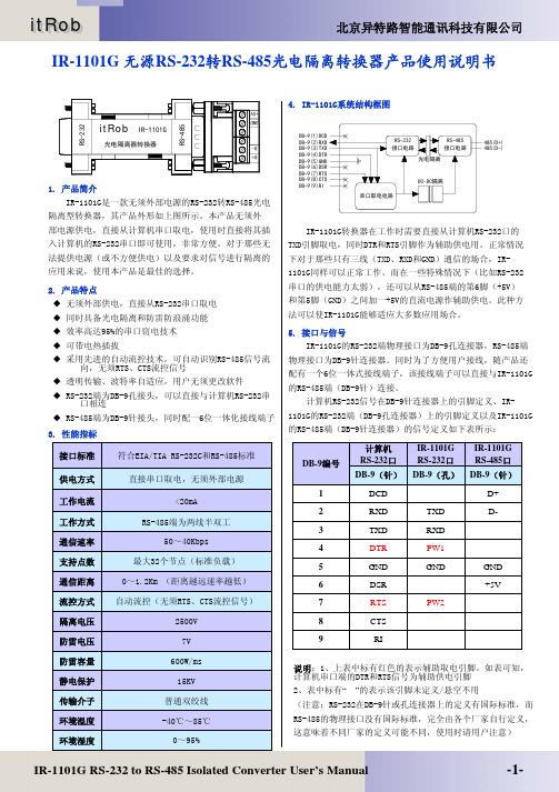
设备接口说明:
① [RS485输入]:与RS485主网连接,A0、B0分别与主网A、B线连接;
1
② [RS485输出]:与RS485子网连接,A1、B1分别与子网的A、B线连
接;
③ 主网与子网的地线端口。其中“地0”接主网地,“地1”接子网地;
④ [DC12V]:直流12V电源输入,为抗干扰器供电,也可以与终端设备
共用12V供电(建议采用优质的直流稳压电源,电流≥300mA);
⑤ 信号输入、输出工作状态指示灯。当灯1亮时,说明主网上有数据发
送,当灯2亮时,指示数据输出到子网;
⑥ 设备工作指示灯,灯亮时设备供电正常;
设备安装简图:
1) 常规安装简图
注:在主网与子网连接过程中,注意将设备的地线分别与主网、子网的
地线连接。在安防监控系统中,通常主网的地为DVR或矩阵的控制地(如果
没有可以接视频的地),子网的地通常为解码器的数据地(如果没有可以接
视频的地)。
2) 典型单主网分与多子网连接图:
在一个较为庞大(大于32点)的RS485控制网络中,由于RS485接收
设备漏电会产生很复杂的“接地”关系,这将直接导致数据传输的准确性。
为了化简此类关系,通常用RS485抗干扰器将一个复杂的大系统,分化成若
干子系统。子系统与其他子系统之间以及各子系统与主系统之间没有电器联
2
系,这样就可以有效防止漏电、地电位等干扰。
3) 远距离中继安装简图:
在施工过程中遇到线缆传输距离过长,而造成数据信号衰减过大,影响
到控制信号的质量(准确率下降造成的控制失灵)时,通常需要在途中增加
本设备来延伸或加强控制信号的有效范围。如图
4) 局部抗干扰:
现场中经常会遇到RS485通讯系统几个子系统连接在一起时就局部或
整体通讯失灵的情况。在这种情况下将不受影响的子系统连在一起,作为主
系统,另外将受影响的子系统连在一起作为子系统,中间用本设备连接如图
便可有效解决失灵问题。如图
3
注意事项:
1) A1、B1不能相互短路或对地1短路
2) 正确连接RS485信号线,注意A B线不可接反;
常见故障及排除方法:
故障现象 原 因 解决方案
工作指示灯不亮
检查供电直流电源是否有输出或正负极接反 检查交流电源是否加电、更换电源或
调整电源正负极
指示灯1、2常亮 A0\B0接反 调整接线方法
工作指示灯亮、指示灯1、2不亮 抗干扰器与RS485主网设备之
间强地干扰
发出RS485信号的设备的地线与设备
的“地0”连接;如没有设备地,请与
系统地连接在一起
指示灯1、2亮
RS485接收设备不
受控
1、接收设备信号线短路;
2、RS485接收设备漏电或距离过远; 3、子网络存在漏电、地电位不平衡; 4、输出信号线(A1\B1)接反 1、检查接收设备信号线是否短路;将
“地1”与连接接收设备的地连接
2、仔细检查隔离后的RS485子网络是
否存在漏电、地电位不平衡