ANSI B92.1-1970 SAE花键标准
- 格式:doc
- 大小:38.00 KB
- 文档页数:5

现代农业2019年7期综合探讨浅析常用渐开线花键标准区别及其应用吴坤(山东常林机械集团股份有限公司,山东临沂276715)[摘要]随着我国与世界联系的日益频繁与深入,进口产品的流通更为广泛,在工程机械和农业机械行业尤为突出,以至各种标准在国内极为常见,以博士力士乐的进口件采用DIN花键标准,日本进口产品采用JIS的花键标准以及美国采用的ANSI、SAE标准等。
以上标准跟我国采用的GB还是有不少差异,文章根据各国标准的特点进行介绍,并与我国GB标准进行比较分析,以便予国内人员提供方便。
[关键词]渐开线;花键;特点;区别中图分类号:TH1314文献标识码:B文章编号院1008-0708(2019)07-100-02在农业机械、工程机械设备中,渐开线花键的使用十分普遍,然而一些核心部件还依赖国外进口在这错综复杂的进口设备中,所采用的渐开线花键标准也是各不相同,这也给国内的行业人员造成很大的困扰,这琳琅满目的各国标标准到底有何异同,下面简单介绍以下各国渐开线花键标准的特点及其应用。
1常用渐开线花键标准的特点1.1常用渐开线花键标准的基本参数在农业机械、工程机械中,常用的渐开线花键多取用以下几种标准,这几种标准的原理是相同的,仅仅侧重点不同。
基本参数的区别详见表1。
表1常用渐开线花键参数表参考标准GB3478\ISO4156 ANSI B92.1 DIN5480 JIS D2001压力角337.5 45 30 37.5 45 30 20模数0.5到10 0.25到2.50.198到10.16(2.5/5到128/256采用双径节制)0.5到10 0.5到10配合与定心齿形齿形、大径齿形直径和齿形齿形|大径齿根类型平|圆圆圆平|圆圆圆平平齿数范围10到100 6到60 6到82 6到40变位系数0 0 外花键-0.05到+0.45内花键+0.05到-0.450.8|其他(极少用)公差等级4|5|6|7| 4|5|6|7| 5|6|7|8|9|10|11|12 自由|滑动|固定|压入齿顶高系数0.5 0.45 0.4 0.5外花键0.5内花键0.4外花键0.5内花键0.30.45x+0.35(内)|x+0.1(外) |x+0.2齿根高系数0.75|0.9 0.7 0.6 见表2外花键0.65内花键0.8外花键0.7内花键0.5拉刀0.55|滚刀0.6|插齿刀0.65|冷轧0.84x+0.1|x-0.8x-0.1常用的渐开线花键标准包括四种不同的标准压力角:20°压力角、30°压力角、37.5°压力角和45°压力角。

第33卷第6期机电产品开发与创新Vol.33,No.6 2020年()月Development&Innovation of Machinery&Electrical Products NOV.,2020文章编号:1002-6673(2020)06-042-03美标渐开线花键综合量规设计张礼才(中国煤炭科工集团太原研究院有限公司,山西太原030032)摘要:介绍了美标渐开线花键的特点,分析了此类花键检测的难点,提出了此类花键综合量规的设计流程,分析了花键综合量规设计的要点,介绍了MATLAB在数值计算领域的优势,编制了美标渐开线花键综合量规参数通用计算程序,以掘采装备关键传动部件为例,计算了花键量规参数,完成了花键量规设计制造$关键词:美标渐开线花键;综合量规;MATLAB;数值计算;掘采装备;关键传动部件中图分类号:TH122文献标识码:A doi:10.3969/j.issn.1002-6673.2020.06.014Design of Integrated Gauge for American Standard Involute SplineZHANG Li-Cai(CCTEG Taiyuan Research Institute,Taiyuan Shanxi030006,China)Abstract:Introduced the characteristics of American standard involute splines‘Analyzed the difficulty of such spline detection,Proposed the design process of this kind of spline integrated gauge"Analyzed the key points in the design of spline integrated gauge, Introduced the advantages of MATLAB in the field of numerical calculation,The general calculation program for the comprehensive gauge parameters of the American standard involute spline is compiled.Take the key transmission components of mining equipment as an example,The parameters of the spline gauge was Calculated, Completed the design and manufacture of spline gauges.Keywords:American standard involute spline;Comprehensive gauge;MATLAB%Numeral calculations;Mining equipment;Key transmission components0引言美标渐开线花键齿形较厚,有利于增加其承载能力,因而在矿用设备中得到了广泛应用'然而,此类花键检测难度较大,采用常规的国标花键量规无法检测美标花键加工制造质量'花键量规的设计计算比较复杂,花键设计参数发生变化,检测花键的量规参数需要重新计算,因此花键量规设计与出图花费时间较长,难以推广应用'为此本文依据美国渐开线花键标准ANSI B92.1-1996,设计了美标渐开线花键量规,基于MATLAB软件,开发了花键量规参数计算程序,花键量规设计与出图花费时间缩短了50%,显著提高了花键量规设计效率。

SAE+J744花键液压泵连接法兰SAE Technical Standards Board Rules provide that: “This report is published by SAE to advance the state of technical and engineering sciences. The use of this report is entirelyvoluntary, and its applicability and suitability for any particular use, including any patent infringement arising therefrom, is the sole responsibility of the user.”SAE reviews each technical report at least every five years at which time it may be reaffirmed, revised, or cancelled. SAE invites your written comments and suggestions.__NS __NG THIS __T: (724) 772-8512 FAX: (724) 776-0243TO PLACE A __T ORDER; (724) 776-4970 FAX: (724) 776-0790http:\\Copyright 1996 Society of Automotive Engineers, Inc.液压泵连接法兰4.1.2The number following the dash (―) states the number of mounting holes in the flange.TABLE 1―__ONS OF 2 AND 4 BOLT PUMP AND MOTOR __G __PilotDimen-sionsANoted50.80(2.000)82.55(3.250)101.60(4.000)127.00(5.000)152.40(6.000)165.10(6.500)177.80(7.000)PilotDimen-sionsWNoted6.4(0.250)6.4(0.250)9.7(0.380)12.7(0.500)12.7(0.500)15.9(0.62 5)15.9(0.625)PilotDimen-sionsXMin――――51(2.00)64(2.50)70(2.75)70(2.75)70(2.75)PilotDimen-sionsYMax0.8(0.03)0.8(0.03)1.5(0.06)1.5(0.06)1.5(0.06)2.3(0.09)2.3(0.09) 2BoltTypeBCastDim.64(2.50)95(3.75)120(4.75)148(5.81)200(7.88)270(10.62)3 00(11.75)2BoltTypeMNoted10.3(0.406)11.1(0.438)14.3(0.562)17.5(0.688)20.6(0.812)27 .0(1.062)27.0(1.062)2BoltTypeP1CastDim.10(0.38)12(0.47)14(0.56)16(0.62)19(0.75)25(1.00)25(1.0 0)4BoltTypeRNoted――――14.3(0.562)14.3(0.562)20.6(0.812)20.6(0.812)27.0( 1.062)4BoltTypeP2CastDim.――――14(0.56)16(0.62)19(0.75)19(0.75)25(1.00)Identi-ficationCode50―(1)(A―A)82―(1)(A)101―(1)(B)127―(1)(C)152―(1)(D)165―(1)(E)177―(1)(F)2 BoltTypeJ14(0.56)18(0.72)25(0.99)31(1.22)40(1.55)55(2.15)60(2.37)2BoltTypeK82.6(3.250)106.4(4.188)146.0(5.750)181.0(7.125)228.6(9.000)317. 5(12.500)350.0(13.781)4BoltTypeS――――89.8(3.536)114.5(4.508)161.6(6.364)224.5(8.839)247.5(9. 745)1.―2 2 Bolt, ―4 4 Bolt Flange液压泵连接法兰FIGURE 1―__ONS OF 2 AND 4 BOLT PUMP AND MOTOR __G __4.24.2.14.2.2Shaft identification codes are found in Tables 2, 3, and 4 and Figures 2 and 3.The number preceding the dash (―) is an approximation, in millimeters, of the shaft major diameter.The number following the dash (―) is arbitrarily assigned as follows:Straight Shaft withoutThread―1Straight Shaft with Thread―2Tapered Shaft with Thread―330 degrees Involute Spline―4液压泵连接法兰TABLE 2―__ONS OF __T SHAFTS―__ AND WITH THREADStraightShaftDS1Max12.70(0.500)15.88(0.625)19.05(0.750)22―(1)(B)25―(1)(B―B)32―(1)(C)38―(1)(C―C)44―(1)(D E)22.22(0.875)25.40(1.000)31.75(1.250)38.10(1.500)44.45(1.750)StraightShaftDS1Min12.67(0.499)15.85(0.624)19.02(0.749)22.20(0.874)25.3 5(0.998)31.70(1.248)38.05(1.498)44.40(1.748)StraightShaftFNoted14.07(0.554)17.60(0.693)21.10(0.831)24.90(0.982)28.10 (1.106)35.20(1.386)42.27(1.664)49.30(1.941)NoThread―1ENoted3.18(0.125)3.97(0.1563)4.78(0.188)6.35(0.250)6.35(0.2 50)7.94(0.3125)9.52(0.375)11.11(0.4375)NoThread―1LLOptional――51(2.00)51(2.00)63(2.50)70(2.75)76(3.00)83(3.25)92(3.62)WithThread―2DTANSI B1.13/8―24UNF 2A1/2―20UNF 2A1/2―20UNF 2A5/8―18UNF 2A3/4―16UNF 2A1―12UNF 2A1-1/8―12UNF 2A1-1/4―12UNF 2AWi thThread―2CNoted2.4(0.094)3.2(0.125)3.2(0.125)4.0(0.156)4.0(0.156)4.0 (0.156)4.0(0.156)4.0(0.156)WithThread―2LC29(1.125)34(1.344)34(1.344)48(1.875)52(2.062)67(2.625)7 3(2.875)89(3.500)WithThread―2LT14.25(0.562)18.25(0.719)18.25(0.719)23.00(0.906)27.00(1. 062)31.00(1.219)34.90(1.375)39.70(1.562)Identi-ficationCode13―(1)(A―A)16―(1)(A)19―(1)StraightShaftLS19(0.750)24(0.938)24(0.938)33(1.312)38(1.500)48(1.875)54(2.125)67(2.625)1.―1 without thread, ―2 with threadFIGURE 2―__ONS OF __T SHAFTS―__ AND WITH THREAD液压泵连接法兰SAE J744 Revised JUN96TABLE 3―__ONS OF TAPER SHAFT ENDS WITH THREAD―3IdentificationCode13―3(A―A)16―3(A)19―322―3(B)25―3(B―B)32―3(C)38―3(C―C)44―3(D E)50―3(F)DS312.70(0.500)15.88(0.625)19.05(0.750)22.22(0.875)25.40(1.00)31.75(1.25) 38.10(1.50)44.45(1.75)50.80(2.00)DTANSI B1.15/16―32UNF 2A1/2―20UNF 2A1/2―20UNF2A5/8―18UNF 2A3/4―16UNF 2A1―12UNF 2A1-1/8―12UNF 2A1-1/4―12UNF 2A1-1/4―12UNF 2ACNoted2.0(0.078)3.2(0.125)3.2(0.125)4.0(0.156)4.0(0.156)4.0(0.156)4.0(0.15 6)4.0(0.156)4.0(0.156)LCT25(0.984)28(1.094)34(1.344)43(1.688)49(1.938)49(1.938)62(2.438)71(2.8 12)90(3.562)LST17.48(0.688)17.48(0.688)23.83(0.938)28.58(1.125)34.92(1.375)34.92(1.37 5)47.62(1.875)53.98(2.125)73.02(2.875)LT12.70(0.500)18.26(0.719)18.26(0.719)23.01(0.906)26.97(1.062)30.96(1.219 )34.92(1.375)39.67(1.562)39.67(1.562)ENoted3.18(0.125)3.97(0.1563)4.78(0.188)6.35(0.250)6.35(0.250)7.94(0.312 5)9.52(0.375)11.11(0.4375)12.70(0.500)ZMax1.63(0.064)2.13(0.084)2.54(0.100)3.33(0.131)3.33(0.131)4.11(0.162)4.9 3(0.194)5.72(0.225)6.50(0.256)ZMin1.37(0.054)1.88(0.074)2.29(0.090)3.07(0.121)3.07(0.121)3.86(0.152)4.6 7(0.184)5.46(0.215)6.25(0.246)FIGURE 3―__ONS OF TAPER SHAFT ENDS WITH THREAD―3液压泵连接法兰TABLE 4―__ONS OF 30 __ __E SPLINE SHAFTS―4Identification Code 13―4 (A―A) 16―4 (A) 19―4 22―4 (B) 25―4 (B―B) 32―4 (C) 38―4 (C―C) 44―4 (D E) 50―4 (F)Spline 9T 20/40 DP 9T 16/32 DP11T 16/32 DP13T 16/32 DP15T 16/32 DP14T 12/24 DP17T 12/24 DP13T 8/16 DP15T 8/16 DPUMin 9.40 (0.3700)11.81 (0.4650)14.99 (0.5900)18.16 (0.7150)21.34 (0.8400)26.42 (1.0400)32.77 (1.2900)36.63 (1.4420)42.95 (1.6910)LAMin 5.1 (0.20) 7.6 (0.30) 8.9 (0.35)10.2 (0.40)12.7 (0.50)15.2(0.60)17.8 (0.70)20.3 (0.80)25.4 (1.00)Lss (1)19 (0.750)24 (0.938)30 (1.180)33 (1.312)38 (1.500)48 (1.875)54 (2.125)67 (2.625)80 (3.125)LB1.5 (0.06)1.5 (0.06)1.5 (0.06)1.5 (0.06)1.5 (0.06)2.3 (0.09)2.3 (0.09)3.0(0.12)3.0 (0.12)1.Lss―Defined as maximum coupler engag ement.5.Preferred Flange/Shaft End Combinations (see Table 5)TABLE 5―FLANGE/SHAFT END __TIONSFlangeSeries50―82―82―101―101―127―127―152―165―177―Shaft EndSeries13―16―19―22―25―32―38―44―44―50―SAE J744CReference(A―A)(A)―(B)(B―B)(C)(C―C)(D)(E)(F)Example: 127―2, 38―4 formerly was“C―C" mounting arrangement, that is, a2 bolt "C" flange with a 1.50 in diameter30 degrees involute spline shaft.6.Flange/Shaft Concentricity―Maintain flange/shaft concentricity within 0.25 mm (0.010 in) in accordance withTables 2, 3, and 4. (Rigid couplings may require closer tolerance.)NotesMarginal Indicia―The change bar (l) located in the left margin is for the convenience of the user in locatingareas where technical revisions have been made to the previous issue of the report. An (R) symbol to the leftof the document title indicates a complete revision of the report.7.7.1__D BY THE SAE COMMON TESTS __AL __EE SC1―__IC __液压泵连接法兰Rationale―The only change was to Table 3, under E Noted, 32―3, the conversion should be 7.94 instead of7.34.Relationship of SAE Standard to ISO Standard―Not applicable.Application―This SAE Standard applies to hydraulic pumps and motors used on off-road self-propelled workmachines as described in categories 1 through 5 of SAE J1116JUN86.ReferencesSAE J390―Dual DimensioningSAE J1116 JUN86―Categories of Off-Road Self-Propelled Work MachinesSAE TSB 003―Rules for SAE Use of SI (Metric) UnitsANSIB1.1―Screw ThreadsANSI B92.1-1970―Involute Splines and InspectionDeveloped by the SAE Common Tests Technical CommitteeSC1―Hydraulic Systems。
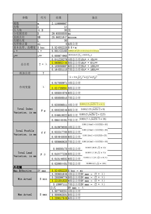
参数代号结果备注模数m 2.116666667齿数z 14压力角φ D 30度分度圆直径D 29.63333333mz 基圆直径DB 25.66321947mzcosa 花键长度L 30齿厚修正量es 0h级公差基本齿厚、齿槽宽S bsc 3.3248522250.5πm i ∗i ∗0.001422168i**i**0.0006749650.0412202794级总公差10i* + 40i** 0.0659524465级总公差16i* + 64i**0.1030506976级总公差25i* + 100i**0.1648811157级总公差40i* + 160i**机加公差T 0.0170889714级总公差0.024*******级总公差0.0358345766级总公差0.0535058187级总公差0.023*******级公差0.0332202465级公差0.0466130226级公差0.0664404917级公差0.0139793334级总公差0.022*******级总公差0.0349483336级总公差0.0556686257级总公差0.008381784级总公差0.010*******级总公差0.0131465326级总公差0.020*******级总公差外花键Max EffectiveSV max 3.324852225S bsc − es 3.2836319464级总公差SV max − (T + λ) 3.2588997795级总公差SV max − (T + λ) 3.2218015286级总公差SV max − (T + λ) 3.159971117级总公差SV max − (T + λ) 公式SV max − λ3.3077632544级总公差3.3000628315级总公差3.2890176496级总公差F βTotal LeadVariation, in mm S maxMax Actual T + λ总公差S min Min Actual λ作用变量 F p Total Index Variation, in mm f f Total Profile Variation, in mm3.2713464077级总公差量棒直径de 4.0641.92/P*25.4invφ D0.053751494tan φ-φinvφ e 0.096433161φ e35.80387度0.09643 Sec φ e 1.233008668跨棒距Me35.70697205偶数齿D b sec φ e + d eMe27.38000768奇数齿(D b cos 90°/N) sec φ e + de外花键。
SAE Technical Standards Board Rules provide that: “This report is published by SAE to advance the state of technical and engineering sciences. The use of this report is entirely voluntary, and its applicability and suitability for any particular use, including any patent infringement arising therefrom, is the sole responsibility of the user.”SAE reviews each technical report at least every five years at which time it may be reaffirmed, revised, or cancelled. SAE invites your written comments and suggestions.QUESTIONS REGARDING THIS DOCUMENT: (724) 772-8512 FAX: (724) 776-0243TO PLACE A DOCUMENT ORDER; (724) 776-4970 FAX: (724) 776-0790http:\\Copyright 1996 Society of Automotive Engineers, Inc.4.1.2The number following the dash (—) states the number of mounting holes in the flange.TABLE 1—DIMENSIONS OF 2 AND 4 BOLT PUMP AND MOTOR MOUNTING FLANGESIdenti-fication Code Pilot Dimen-sions A Noted Pilot Dimen-sions W Noted Pilot Dimen-sions X Min Pilot Dimen-sions Y Max 2 Bolt Type B Cast Dim. 2 Bolt Type J 2 Bolt Type K 2 Bolt Type M Noted 2 Bolt Type P 1Cast Dim. 4 Bolt Type S 4 Bolt Type R Noted 4 Bolt Type P 2Cast Dim.50—(1)1.—2 2 Bolt, —4 4 Bolt Flange50.80 6.4—0.8641482.610.310———(A—A)(2.000)(0.250)—(0.03)(2.50)(0.56)(3.250)(0.406)(0.38)———82—(1)82.55 6.4—0.89518106.411.112———(A)(3.250)(0.250)—(0.03)(3.75)(0.72)(4.188)(0.438)(0.47)———101—(1)101.609.751 1.512025146.014.31489.814.314(B)(4.000)(0.380)(2.00)(0.06)(4.75)(0.99)(5.750)(0.562)(0.56)(3.536)(0.562)(0.56)127—(1)127.0012.764 1.514831181.017.516114.514.316(C)(5.000)(0.500)(2.50)(0.06)(5.81)(1.22)(7.125)(0.688)(0.62)(4.508)(0.562)(0.62)152—(1)152.4012.770 1.520040228.620.619161.620.619(D)(6.000)(0.500)(2.75)(0.06)(7.88)(1.55)(9.000)(0.812)(0.75)(6.364)(0.812)(0.75)165—(1)165.1015.970 2.327055317.527.025224.520.619(E)(6.500)(0.625)(2.75)(0.09)(10.62)(2.15)(12.500)(1.062)(1.00)(8.839)(0.812)(0.75)177—(1)177.8015.970 2.330060350.027.025247.527.025(F)(7.000)(0.625)(2.75)(0.09)(11.75)(2.37)(13.781)(1.062)(1.00)(9.745)(1.062)(1.00)FIGURE 1—DIMENSIONS OF 2 AND 4 BOLT PUMP AND MOTOR MOUNTING FLANGES 4.2Shaft identification codes are found in Tables 2, 3, and 4 and Figures 2 and 3.4.2.1The number preceding the dash (—) is an approximation, in millimeters, of the shaft major diameter.4.2.2The number following the dash (—) is arbitrarily assigned as follows:Straight Shaft without Thread—1Straight Shaft with Thread—2Tapered Shaft with Thread—330 degrees Involute Spline—4FIGURE 2—DIMENSIONS OF STRAIGHT SHAFTS—WITHOUT AND WITH THREADTABLE 2—DIMENSIONS OF STRAIGHT SHAFTS—WITHOUT AND WITH THREADIdenti-fication Code Straight Shaft D S1Max Straight Shaft D S1Min Straight Shaft L SStraight Shaft F Noted No Thread —1E Noted No Thread —1L L OptionalWith Thread —2D TANSI B1.1With Thread —2C Noted With Thread —2L C With Thread —2L T 13—(1)1.—1 without thread, —2 with thread12.7012.671914.07 3.18—3/8—24 2.42914.25(A—A)(0.500)(0.499)(0.750)(0.554)(0.125)—UNF 2A (0.094)(1.125)(0.562)16—(1)15.8815.852417.60 3.97511/2—20 3.23418.25(A)(0.625)(0.624)(0.938)(0.693)(0.1563)(2.00)UNF 2A (0.125)(1.344)(0.719)19—(1)19.0519.022421.10 4.78511/2—20 3.23418.25(0.750)(0.749)(0.938)(0.831)(0.188)(2.00)UNF 2A (0.125)(1.344)(0.719)22—(1)22.2222.203324.90 6.35635/8—18 4.04823.00(B)(0.875)(0.874)(1.312)(0.982)(0.250)(2.50)UNF 2A (0.156)(1.875)(0.906)25—(1)25.4025.353828.10 6.35703/4—16 4.05227.00(B—B)(1.000)(0.998)(1.500)(1.106)(0.250)(2.75)UNF 2A (0.156)(2.062)(1.062)32—(1)31.7531.704835.207.94761—12 4.06731.00(C)(1.250)(1.248)(1.875)(1.386)(0.3125)(3.00)UNF 2A (0.156)(2.625)(1.219)38—(1)38.1038.055442.279.52831-1/8—12 4.07334.90(C—C)(1.500)(1.498)(2.125)(1.664)(0.375)(3.25)UNF 2A (0.156)(2.875)(1.375)44—(1)44.4544.406749.3011.11921-1/4—12 4.08939.70(D & E)(1.750)(1.748)(2.625)(1.941)(0.4375)(3.62)UNF 2A(0.156)(3.500)(1.562)FIGURE 3—DIMENSIONS OF T APER SHAFT ENDS WITH THREAD—3TABLE 3—DIMENSIONS OF TAPER SHAFT ENDS WITH THREAD—3IdentificationCodeD S3D TANSI B1.1C Noted L CT L ST L T E Noted Z Max Z Min 13—312.705/16—32 2.02517.4812.70 3.18 1.63 1.37(A—A)(0.500)UNF 2A (0.078)(0.984)(0.688)(0.500)(0.125)(0.064)(0.054)16—315.881/2—20 3.22817.4818.26 3.97 2.13 1.88(A)(0.625)UNF 2A (0.125)(1.094)(0.688)(0.719)(0.1563)(0.084)(0.074)19—319.051/2—20 3.23423.8318.26 4.78 2.54 2.29(0.750)UNF 2A (0.125)(1.344)(0.938)(0.719)(0.188)(0.100)(0.090)22—322.225/8—18 4.04328.5823.01 6.35 3.33 3.07(B)(0.875)UNF 2A (0.156)(1.688)(1.125)(0.906)(0.250)(0.131)(0.121)25—325.403/4—16 4.04934.9226.97 6.35 3.33 3.07(B—B)(1.00)UNF 2A (0.156)(1.938)(1.375)(1.062)(0.250)(0.131)(0.121)32—331.751—12 4.04934.9230.967.94 4.11 3.86(C)(1.25)UNF 2A (0.156)(1.938)(1.375)(1.219)(0.3125)(0.162)(0.152)38—338.101-1/8—12 4.06247.6234.929.52 4.93 4.67(C—C)(1.50)UNF 2A (0.156)(2.438)(1.875)(1.375)(0.375)(0.194)(0.184)44—344.451-1/4—12 4.07153.9839.6711.11 5.72 5.46(D & E)(1.75)UNF 2A (0.156)(2.812)(2.125)(1.562)(0.4375)(0.225)(0.215)50—350.801-1/4—12 4.09073.0239.6712.70 6.50 6.25(F)(2.00)UNF 2A(0.156)(3.562)(2.875)(1.562)(0.500)(0.256)(0.246)5.Preferred Flange/Shaft End Combinations (see Table 5)6.Flange/Shaft Concentricity—Maintain flange/shaft concentricity within 0.25 mm (0.010 in) in accordance with Tables 2, 3, and 4. (Rigid couplings may require closer tolerance.)7.Notes7.1Marginal Indicia—The change bar (l) located in the left margin is for the convenience of the user in locating areas where technical revisions have been made to the previous issue of the report. An (R) symbol to the left of the document title indicates a complete revision of the report.PREPARED BY THE SAE COMMON TESTS TECHNICAL COMMITTEE SC1—HYDRAULIC SYSTEMSTABLE 4—DIMENSIONS OF 30 DEGREES INVOLUTE SPLINE SHAFTS—4Identification Code Spline U Min L A Min L ss (1)1.L ss —Defined as maximum coupler engagement.L B 13—4 (A—A) 9T 20/40 DP 9.40 (0.3700) 5.1 (0.20)19 (0.750) 1.5 (0.06) 16—4 (A) 9T 16/32 DP 11.81 (0.4650) 7.6 (0.30)24 (0.938) 1.5 (0.06) 19—411T 16/32 DP 14.99 (0.5900) 8.9 (0.35)30 (1.180) 1.5 (0.06) 22—4 (B)13T 16/32 DP 18.16 (0.7150)10.2 (0.40)33 (1.312) 1.5 (0.06) 25—4 (B—B)15T 16/32 DP 21.34 (0.8400)12.7 (0.50)38 (1.500) 1.5 (0.06) 32—4 (C)14T 12/24 DP 26.42 (1.0400)15.2 (0.60)48 (1.875) 2.3 (0.09) 38—4 (C—C)17T 12/24 DP 32.77 (1.2900)17.8 (0.70)54 (2.125) 2.3 (0.09) 44—4 (D & E)13T 8/16 DP 36.63 (1.4420)20.3 (0.80)67 (2.625) 3.0 (0.12) 50—4 (F)15T 8/16 DP42.95 (1.6910)25.4 (1.00)80 (3.125)3.0 (0.12)TABLE 5—FLANGE/SHAFT END COMBINATIONSFlange Series Shaft End Series SAE J744C Reference 50—13—(A—A)82—16—(A)82—19——101—22—(B)101—25—(B—B)127—32—(C)127—38—(C—C)152—44—(D)165—44—(E)177—50—(F)Example: 127—2, 38—4 formerly was "C—C" mounting arrangement, that is, a 2 bolt "C" flange with a 1.50 in diameter 30 degrees involute spline shaft.Rationale—The only change was to Table 3, under E Noted, 32—3, the conversion should be 7.94 instead of7.34.Relationship of SAE Standard to ISO Standard—Not applicable.Application—This SAE Standard applies to hydraulic pumps and motors used on off-road self-propelled work machines as described in categories 1 through 5 of SAE J1116 JUN86.ReferencesSAE J390—Dual DimensioningSAE J1116 JUN86—Categories of Off-Road Self-Propelled Work MachinesSAE TSB 003—Rules for SAE Use of SI (Metric) UnitsANSI B1.1—Screw ThreadsANSI B92.1-1970—Involute Splines and InspectionDeveloped by the SAE Common Tests Technical Committee SC1—Hydraulic Systems。
SAE花键标准简介(doc 5页)_NewLead Variation is the variation of the direction of the spline tooth from its intended direction parallel to the reference axis, also including parallelism and alignment variations (see Fig. 1a). Note: Straight (nonhelical) splines have an infinite lead.导向公差:导向公差是花键的键齿的实际齿线与花键的参考轴线之间的平行度公差,这个公差包括平行度公差和圆周阵列公差(见图Fig.1a)。
注意:直齿花键(非螺旋花键)的导向公差为无穷大。
译者注:这一条解释有待斟酌。
Length of Engagement (Lq) is the axial length of contact between mating splines.结合长度(Lq):结合长度是两个相互配合的内、外花键之间的接触段的长度。
Machining Tolerance (m) is the permissible variation in actual space width or actual tooth thickness.加工公差(m):加工公差是花键的实际齿槽宽和实际齿厚的允许的变动量。
译者注:在《GB/T 3478.1-1995 圆柱直齿渐开线花键》中,将加工公差定义为T。
Major Circle is the circle formed by the outermost surface of the spline. It is the outside circle (tooth tip circle) of the external spline or the root circle of the internal spline.大圆:大圆是花键的最大齿形面的包络圆。
ansi b92.1a-1976花键规格
ANSI B92.1A-1976是一项关于花键规格的标准,它规定了花键的几何尺寸以及制造和设计要求等方面的要求。
这项标准对于机械制造和设计行业非常重要,下面我们来详细了解一下。
一、花键的定义
花键是一种用于固定轴和销等旋转件的机械零件,通常采用直角槽形状,由内联花键槽和外侧花键零件两部分组成。
二、花键的几何尺寸
ANSI B92.1A-1976规定了花键的几何尺寸,包括内径、外径、长度、圆角半径等等。
这些尺寸的严格规范确定了花键的制作标准,确保了花键与配合件的完美匹配。
三、花键的制造和设计要求
除了尺寸规定,ANSI B92.1A-1976还对花键的制造和设计要求做出了详细规定。
其中包括:
1. 材料:花键应该采用高强度的合金钢或不锈钢,并具有足够的刚性和韧性。
2. 表面处理:花键应该进行表面硬化处理,提高其硬度和耐磨性。
3. 安装标准:花键应该按照设计要求与轴配合,确保其准确而牢固地固定在轴上。
4. 承受负载能力:花键应该满足其设计要求下的承受负载能力,确保其能够承受应力和压力。
SAE Technical Standards Board Rules provide that: “This report is published by SAE to advance the state of technical and engineering sciences. The use of this report is entirely voluntary, and its applicability and suitability for any particular use, including any patent infringement arising therefrom, is the sole responsibility of the user.”SAE reviews each technical report at least every five years at which time it may be reaffirmed, revised, or cancelled. SAE invites your written comments and suggestions.QUESTIONS REGARDING THIS DOCUMENT: (724) 772-8512 FAX: (724) 776-0243TO PLACE A DOCUMENT ORDER; (724) 776-4970 FAX: (724) 776-0790http:\\Copyright 1996 Society of Automotive Engineers, Inc.4.1.2The number following the dash (—) states the number of mounting holes in the flange.TABLE 1—DIMENSIONS OF 2 AND 4 BOLT PUMP AND MOTOR MOUNTING FLANGESIdenti-fication Code Pilot Dimen-sions A Noted Pilot Dimen-sions W Noted Pilot Dimen-sions X Min Pilot Dimen-sions Y Max 2 Bolt Type B Cast Dim. 2 Bolt Type J 2 Bolt Type K 2 Bolt Type M Noted 2 Bolt Type P 1Cast Dim. 4 Bolt Type S 4 Bolt Type R Noted 4 Bolt Type P 2Cast Dim.50—(1)1.—2 2 Bolt, —4 4 Bolt Flange50.80 6.4—0.8641482.610.310———(A—A)(2.000)(0.250)—(0.03)(2.50)(0.56)(3.250)(0.406)(0.38)———82—(1)82.55 6.4—0.89518106.411.112———(A)(3.250)(0.250)—(0.03)(3.75)(0.72)(4.188)(0.438)(0.47)———101—(1)101.609.751 1.512025146.014.31489.814.314(B)(4.000)(0.380)(2.00)(0.06)(4.75)(0.99)(5.750)(0.562)(0.56)(3.536)(0.562)(0.56)127—(1)127.0012.764 1.514831181.017.516114.514.316(C)(5.000)(0.500)(2.50)(0.06)(5.81)(1.22)(7.125)(0.688)(0.62)(4.508)(0.562)(0.62)152—(1)152.4012.770 1.520040228.620.619161.620.619(D)(6.000)(0.500)(2.75)(0.06)(7.88)(1.55)(9.000)(0.812)(0.75)(6.364)(0.812)(0.75)165—(1)165.1015.970 2.327055317.527.025224.520.619(E)(6.500)(0.625)(2.75)(0.09)(10.62)(2.15)(12.500)(1.062)(1.00)(8.839)(0.812)(0.75)177—(1)177.8015.970 2.330060350.027.025247.527.025(F)(7.000)(0.625)(2.75)(0.09)(11.75)(2.37)(13.781)(1.062)(1.00)(9.745)(1.062)(1.00)FIGURE 1—DIMENSIONS OF 2 AND 4 BOLT PUMP AND MOTOR MOUNTING FLANGES 4.2Shaft identification codes are found in Tables 2, 3, and 4 and Figures 2 and 3.4.2.1The number preceding the dash (—) is an approximation, in millimeters, of the shaft major diameter.4.2.2The number following the dash (—) is arbitrarily assigned as follows:Straight Shaft without Thread—1Straight Shaft with Thread—2Tapered Shaft with Thread—330 degrees Involute Spline—4FIGURE 2—DIMENSIONS OF STRAIGHT SHAFTS—WITHOUT AND WITH THREADTABLE 2—DIMENSIONS OF STRAIGHT SHAFTS—WITHOUT AND WITH THREADIdenti-fication Code Straight Shaft D S1Max Straight Shaft D S1Min Straight Shaft L SStraight Shaft F Noted No Thread —1E Noted No Thread —1L L OptionalWith Thread —2D TANSI B1.1With Thread —2C Noted With Thread —2L C With Thread —2L T 13—(1)1.—1 without thread, —2 with thread12.7012.671914.07 3.18—3/8—24 2.42914.25(A—A)(0.500)(0.499)(0.750)(0.554)(0.125)—UNF 2A (0.094)(1.125)(0.562)16—(1)15.8815.852417.60 3.97511/2—20 3.23418.25(A)(0.625)(0.624)(0.938)(0.693)(0.1563)(2.00)UNF 2A (0.125)(1.344)(0.719)19—(1)19.0519.022421.10 4.78511/2—20 3.23418.25(0.750)(0.749)(0.938)(0.831)(0.188)(2.00)UNF 2A (0.125)(1.344)(0.719)22—(1)22.2222.203324.90 6.35635/8—18 4.04823.00(B)(0.875)(0.874)(1.312)(0.982)(0.250)(2.50)UNF 2A (0.156)(1.875)(0.906)25—(1)25.4025.353828.10 6.35703/4—16 4.05227.00(B—B)(1.000)(0.998)(1.500)(1.106)(0.250)(2.75)UNF 2A (0.156)(2.062)(1.062)32—(1)31.7531.704835.207.94761—12 4.06731.00(C)(1.250)(1.248)(1.875)(1.386)(0.3125)(3.00)UNF 2A (0.156)(2.625)(1.219)38—(1)38.1038.055442.279.52831-1/8—12 4.07334.90(C—C)(1.500)(1.498)(2.125)(1.664)(0.375)(3.25)UNF 2A (0.156)(2.875)(1.375)44—(1)44.4544.406749.3011.11921-1/4—12 4.08939.70(D & E)(1.750)(1.748)(2.625)(1.941)(0.4375)(3.62)UNF 2A(0.156)(3.500)(1.562)FIGURE 3—DIMENSIONS OF T APER SHAFT ENDS WITH THREAD—3TABLE 3—DIMENSIONS OF TAPER SHAFT ENDS WITH THREAD—3IdentificationCodeD S3D TANSI B1.1C Noted L CT L ST L T E Noted Z Max Z Min 13—312.705/16—32 2.02517.4812.70 3.18 1.63 1.37(A—A)(0.500)UNF 2A (0.078)(0.984)(0.688)(0.500)(0.125)(0.064)(0.054)16—315.881/2—20 3.22817.4818.26 3.97 2.13 1.88(A)(0.625)UNF 2A (0.125)(1.094)(0.688)(0.719)(0.1563)(0.084)(0.074)19—319.051/2—20 3.23423.8318.26 4.78 2.54 2.29(0.750)UNF 2A (0.125)(1.344)(0.938)(0.719)(0.188)(0.100)(0.090)22—322.225/8—18 4.04328.5823.01 6.35 3.33 3.07(B)(0.875)UNF 2A (0.156)(1.688)(1.125)(0.906)(0.250)(0.131)(0.121)25—325.403/4—16 4.04934.9226.97 6.35 3.33 3.07(B—B)(1.00)UNF 2A (0.156)(1.938)(1.375)(1.062)(0.250)(0.131)(0.121)32—331.751—12 4.04934.9230.967.94 4.11 3.86(C)(1.25)UNF 2A (0.156)(1.938)(1.375)(1.219)(0.3125)(0.162)(0.152)38—338.101-1/8—12 4.06247.6234.929.52 4.93 4.67(C—C)(1.50)UNF 2A (0.156)(2.438)(1.875)(1.375)(0.375)(0.194)(0.184)44—344.451-1/4—12 4.07153.9839.6711.11 5.72 5.46(D & E)(1.75)UNF 2A (0.156)(2.812)(2.125)(1.562)(0.4375)(0.225)(0.215)50—350.801-1/4—12 4.09073.0239.6712.70 6.50 6.25(F)(2.00)UNF 2A(0.156)(3.562)(2.875)(1.562)(0.500)(0.256)(0.246)5.Preferred Flange/Shaft End Combinations (see Table 5)6.Flange/Shaft Concentricity—Maintain flange/shaft concentricity within 0.25 mm (0.010 in) in accordance with Tables 2, 3, and 4. (Rigid couplings may require closer tolerance.)7.Notes7.1Marginal Indicia—The change bar (l) located in the left margin is for the convenience of the user in locating areas where technical revisions have been made to the previous issue of the report. An (R) symbol to the left of the document title indicates a complete revision of the report.PREPARED BY THE SAE COMMON TESTS TECHNICAL COMMITTEE SC1—HYDRAULIC SYSTEMSTABLE 4—DIMENSIONS OF 30 DEGREES INVOLUTE SPLINE SHAFTS—4Identification Code Spline U Min L A Min L ss (1)1.L ss —Defined as maximum coupler engagement.L B 13—4 (A—A) 9T 20/40 DP 9.40 (0.3700) 5.1 (0.20)19 (0.750) 1.5 (0.06) 16—4 (A) 9T 16/32 DP 11.81 (0.4650) 7.6 (0.30)24 (0.938) 1.5 (0.06) 19—411T 16/32 DP 14.99 (0.5900) 8.9 (0.35)30 (1.180) 1.5 (0.06) 22—4 (B)13T 16/32 DP 18.16 (0.7150)10.2 (0.40)33 (1.312) 1.5 (0.06) 25—4 (B—B)15T 16/32 DP 21.34 (0.8400)12.7 (0.50)38 (1.500) 1.5 (0.06) 32—4 (C)14T 12/24 DP 26.42 (1.0400)15.2 (0.60)48 (1.875) 2.3 (0.09) 38—4 (C—C)17T 12/24 DP 32.77 (1.2900)17.8 (0.70)54 (2.125) 2.3 (0.09) 44—4 (D & E)13T 8/16 DP 36.63 (1.4420)20.3 (0.80)67 (2.625) 3.0 (0.12) 50—4 (F)15T 8/16 DP42.95 (1.6910)25.4 (1.00)80 (3.125)3.0 (0.12)TABLE 5—FLANGE/SHAFT END COMBINATIONSFlange Series Shaft End Series SAE J744C Reference 50—13—(A—A)82—16—(A)82—19——101—22—(B)101—25—(B—B)127—32—(C)127—38—(C—C)152—44—(D)165—44—(E)177—50—(F)Example: 127—2, 38—4 formerly was "C—C" mounting arrangement, that is, a 2 bolt "C" flange with a 1.50 in diameter 30 degrees involute spline shaft.Rationale—The only change was to Table 3, under E Noted, 32—3, the conversion should be 7.94 instead of7.34.Relationship of SAE Standard to ISO Standard—Not applicable.Application—This SAE Standard applies to hydraulic pumps and motors used on off-road self-propelled work machines as described in categories 1 through 5 of SAE J1116 JUN86.ReferencesSAE J390—Dual DimensioningSAE J1116 JUN86—Categories of Off-Road Self-Propelled Work MachinesSAE TSB 003—Rules for SAE Use of SI (Metric) UnitsANSI B1.1—Screw ThreadsANSI B92.1-1970—Involute Splines and InspectionDeveloped by the SAE Common Tests Technical Committee SC1—Hydraulic Systems。
D a t a S h e e t11064890 • Rev A • Apr2009联系地址:萨澳行走液压(上海)有限公司中国 上海 桂平路418号兴园科技广场309室 邮政编码:200233电话:86-21-64950505 传真:86-21-64952622T90变量柱塞泵75/100 cc/revT90 变量柱塞泵75/100 cc/rev简介萨澳-丹佛斯公司推出了新型混凝土搅拌车用T90变量柱塞泵,它的开发源于本公司产品在混凝土搅拌车市场中三十余年的全球应用经验。
更加紧凑的外形,重量轻和更高的效率是新款T90变量柱塞泵的最大优点。
新款T90变量柱塞泵是在萨澳-丹佛斯成熟90系列变量柱塞泵的基础上加以改进,使之更加适合应用在混凝土搅拌车上。
新款T90变量柱塞泵具更小的外形尺寸,更加便于安装。
拥有更高的效率,和功率密度,同时采用手动控制。
系统原理图AB特 点·高质量和可靠性的设计–被验证的最优9柱塞旋转组件 –专用变量斜盘设计–在成熟90系列技术的基础上加以改进,使之更加适用于 混凝土搅拌车的应用 –高效的集成补油泵–可选择排量为75/100cc/rev·更为小的外形尺寸,并且便于安装–外形尺寸更加小,给安装带来了较大的自由度 –更高的功率密度 –集成了高压溢流阀 –系统A,B口全部为公制螺纹 –手动控制·更高的效率–更高的效率,系统能量损失更少 –能在发动机低速时给系统提供更高的压力© Copyright 2009, Sauer-Danfoss. All rights reserved. Contents subject to change.11064890 • Rev A • Apr2009T90 变量柱塞泵75/100 cc/rev工作参数特征技术规格T90外形图(T90 变量柱塞泵外形图(油口测压口 M2 系统压力 B 油口 L1 壳体泄油口测压口 M2 系统压力 B 油口 L1 壳体泄油口油口"Z"视图[-0.005]系统压力额定bar [psi]420 [6000]最高480 [7000]主油路最低压力10 [150]吸油口压力 (补油泵入口)最低(持续)bar (绝对压力)[in. Hg vac.]0.7 [9]最低(冷启动)0.2 [24]壳体压力持续bar [psi]3 [40]最高(冷启动)5 [75]。
浅析常用渐开线花键标准区别及其应用作者:吴坤来源:《现代农业·汉文版》 2019年第7期吴坤(山东常林机械集团股份有限公司,山东临沂 276715)[摘要] 随着我国与世界联系的日益频繁与深入,进口产品的流通更为广泛,在工程机械和农业机械行业尤为突出,以至各种标准在国内极为常见,以博士力士乐的进口件采用DIN花键标准,日本进口产品采用JIS的花键标准以及美国采用的ANSI、SAE标准等。
以上标准跟我国采用的GB还是有不少差异,文章根据各国标准的特点进行介绍,并与我国GB标准进行比较分析,以便予国内人员提供方便。
[关键词] 渐开线;花键;特点;区别中图分类号:TH1314文献标识码:B文章编号:1008-0708(2019)07-100-02在农业机械、工程机械设备中,渐开线花键的使用十分普遍,然而一些核心部件还依赖国外进口在这错综复杂的进口设备中,所采用的渐开线花键标准也是各不相同,这也给国内的行业人员造成很大的困扰,这琳琅满目的各国标标准到底有何异同,下面简单介绍以下各国渐开线花键标准的特点及其应用。
1 常用渐开线花键标准的特点1.1 常用渐开线花键标准的基本参数在农业机械、工程机械中,常用的渐开线花键多取用以下几种标准,这几种标准的原理是相同的,仅仅侧重点不同。
基本参数的区别详见表1。
常用的渐开线花键标准包括四种不同的标准压力角:20°压力角、30°压力角、37.5°压力角和45°压力角。
我国国标GB3478.1与国际ISO4156标准一致,常用30°的标准压力角,其它压力角在特殊场合也会使用。
在花键的加工时采用零变位,公差采用4、5、6、7四个等级。
一般取公差5级,其它等级与公差5级的倍数关系为:Class4=0.71,Class5=1,Class6=1.4,Class7=2.0;德标DIN5480花键是基于基准直径的一种渐开线花键,因齿数模数的不同而影响变位系数的变化,并且它的公差等级比较多(有8种),选用时也更加精准,其9级相当于GB的5级公差,DIN5480甚至将花键的加工方法也考虑在内,根据加工方法的不同选用不同的系数(详见表1)。
ANSI B92.1-1970 SAE花键标准INVOLUTE SPLINES渐开线花键Form Circle is the circle which defines the deepest points of involute form control of the tooth profile. This circle along with the tooth tip circle (or start of chamfer circle) determines the limits of tooth profile requiring control. It is located near the major circle on the internal spline and near the minor circle on the external spline.渐开线终止圆:渐开线终止圆是用于控制齿廓上渐开线的极限距离的圆。
渐开线终止圆与齿顶圆(或者修缘线的起点所在的圆)共同限制了所要求控制的渐开线齿廓的范围。
渐开线终止圆的位置靠近内花键的大圆(齿根圆)或者外花键的小圆(齿根圆)。
译者注:这段话的意思是:只有在渐开线终止圆与齿顶圆(或者修缘线的起点所在的圆)之间的花键的齿形为渐开线齿形,其余部分不一定按照渐开线成形。
译者注2:在《GB/T 3478.1-1995 圆柱直齿渐开线花键》中,将Form Cycle定义为两个圆:内花键的渐开线终止圆和外花键的渐开线起始圆。
而在本标准中,将这两个圆统称为Form Cycle,译者将Form Cycle翻译为渐开线终止圆。
Form Clearance (c F) is the radial depth of involute profile beyond the depth of engagement with the mating part. It allows for looseness between mating splines and for eccentricities between the minor circle (internal), the major circle (external), and their respective pitch circles.齿形裕度:齿形裕度(c F)是相互配合的内、外花键的渐开线齿廓在径向方向上的间隙。
齿形裕度是的相互配合的内、外花键之间能够存在一定松动,并且是的内花键的小圆(齿顶圆)、外花键的大圆(齿顶圆)、以及内、外花键各自的节圆之间存在一定的偏心距。
Form Diameter (D Fe, D Fi) the diameter of the form circle.渐开线终止圆直径(D Fe, D Fi):渐开线终止圆所在圆的直径。
Internal Spline is a spline formed on the inner surface of a cylinder.内花键:在圆柱体的孔的内表面形成的花键。
Involute Spline is one having teeth with involute profiles.渐开线花键:花键的键齿的齿形为渐开线形式的花键。
Lead Variation is the variation of the direction of the spline tooth from its intended direction parallel to the reference axis, also including parallelism and alignment variations (see Fig. 1a). Note: Straight (nonhelical) splines have an infinite lead.导向公差:导向公差是花键的键齿的实际齿线与花键的参考轴线之间的平行度公差,这个公差包括平行度公差和圆周阵列公差(见图Fig.1a)。
注意:直齿花键(非螺旋花键)的导向公差为无穷大。
译者注:这一条解释有待斟酌。
Length of Engagement (L q) is the axial length of contact between mating splines.结合长度(L q):结合长度是两个相互配合的内、外花键之间的接触段的长度。
Machining Tolerance (m) is the permissible variation in actual space width or actual tooth thickness.加工公差(m):加工公差是花键的实际齿槽宽和实际齿厚的允许的变动量。
译者注:在《GB/T 3478.1-1995 圆柱直齿渐开线花键》中,将加工公差定义为T。
Major Circle is the circle formed by the outermost surface of the spline. It is the outside circle (tooth tip circle) of the external spline or the root circle of the internal spline.大圆:大圆是花键的最大齿形面的包络圆。
它是外花键的外圆(齿顶圆),和内花键的齿根圆。
Major Diameter (D o, D ri) is the diameter of the major circle.大圆直径:大圆直径(D o, D ri)是大圆所在圆的直径。
译者注:在《GB/T 3478.1-1995 圆柱直齿渐开线花键》中,将大圆直径定义为:内花键D ei、外花键D ee。
Minor Circle is the circle formed by the innermost surface of the spline. It is the root circle of the external spline or the inside circle (tooth tip circle) of the internal spline.小圆:小圆是花键的最小齿形面的排斥圆。
它是外花键的齿根圆,和内花键的内圆(齿顶圆)。
Minor Diameter (D re, D i) is the diameter of the minor circle.小圆直径:小圆直径(D re, D i)是小圆所在圆的直径。
译者注:在《GB/T 3478.1-1995 圆柱直齿渐开线花键》中,将小圆直径定义为:内花键D ii、外花键D ie。
Nominal Clearance is the actual space width of an internal spline minus the actual tooth thickness of the mating external spline. It does not define the fit between mating members, because of the effect of variations.理论侧隙:理论侧隙是内花键的实际齿槽宽减去与之相互配合的外花键的实际齿厚所得的值。
由于内、外花键在配合时会产生一定的公差,所以理论侧隙不能够用于确定相互配合的内、外花键之间的间隙。
Out of Roundness is the variation of the spline from a true circular configuration.圆度:圆度是花键与真圆的圆廓之间的公差。
Parallelism Variation is the variation of parallelism of a single spline tooth with respect to any other single spline tooth (see Fig. 1b).平行度公差:平行度公差是单根键齿相对其它的单根键齿之间的平行度公差。
(见图Fig.1b)Pitch (P/P s) is a combination number of a one-to-two ratio indicating the spline proportions; the upper or first number is the diametral pitch, the lower or second number is the stub pitch and denotes, as that fractional part of an inch, the basic radial length of engagement, both above and below the pitch circle.径节分数(P/P s):径节分数是由两个数组成的一个比率,它表示的是花键的比例;设这个比率为A/B(这个分数用英寸表示),则在这个分数中第一个数(分子)A表示的是花键的径节,第二个数(分母)B表示的是残余径节,径节表示的是在节圆上方的键齿在半径方向上的结合长度,残余径节表示的是在节圆下方的键齿在半径方向上的结合长度。
译者注:可以理解为节圆将整个花键键齿一分为二,节圆上方的键齿的齿高为径节,节圆下方的键齿的齿高为残余径节。
在实际计算时要考虑到渐开线终止圆与修缘线所在圆对键齿有效结合齿高的影响,并将其扣除。
Pitch Circle is the reference circle from which all transverse spline tooth dimensions are constructed.节圆:节圆是一个参考圆,花键的键齿的所有的横向尺寸都是以节圆为基础开始计算的。
Pitch Diameter (D) is the diameter of the pitch circle.节圆直径(D):节圆直径是节圆所在圆的直径。
Pitch Point is the intersection of the spline tooth profile with the pitch circle.节点:节点是键齿的齿廓与节圆的交点。
Pressure Angle (φ) is the angle between a line tangent to an involute and a radial line through the point of tangency. Unless otherwise specified, it is the standard pressure angle.压力角(φ):压力角是花键的渐开线齿廓的切线与通过切点的半径所组成的夹角。