SR Drive for Hydraulic Pump using a Novel Passive Boost Converter
- 格式:pdf
- 大小:706.71 KB
- 文档页数:6
液压系统液压传动和气压传动称为流体传动,是根据17世纪帕斯卡提出的液体静压力传动原理而发展起来的一门新兴技术,1795年英国约瑟夫•布拉曼(Joseph Braman,1749-1814),在伦敦用水作为工作介质,以水压机的形式将其应用于工业上,诞生了世界上第一台水压机。
1905年将工作介质水改为油,又进一步得到改善。
第一次世界大战(1914-1918)后液压传动广泛应用,特别是1920年以后,发展更为迅速。
液压元件大约在19 世纪末20 世纪初的20年间,才开始进入正规的工业生产阶段。
1925 年维克斯(F.Vikers)发明了压力平衡式叶片泵,为近代液压元件工业或液压传动的逐步建立奠定了基础。
20 世纪初康斯坦丁•尼斯克(G•Constantimsco)对能量波动传递所进行的理论及实际研究;1910年对液力传动(液力联轴节、液力变矩器等)方面的贡献,使这两方面领域得到了发展。
第二次世界大战(1941-1945)期间,在美国机床中有30%应用了液压传动。
应该指出,日本液压传动的发展较欧美等国家晚了近20 多年。
在1955 年前后, 日本迅速发展液压传动,1956 年成立了“液压工业会”。
近20~30 年间,日本液压传动发展之快,居世界领先地位。
液压传动有许多突出的优点,因此它的应用非常广泛,如一般工业用的塑料加工机械、压力机械、机床等;行走机械中的工程机械、建筑机械、农业机械、汽车等;钢铁工业用的冶金机械、提升装置、轧辊调整装置等;土木水利工程用的防洪闸门及堤坝装置、河床升降装置、桥梁操纵机构等;发电厂涡轮机调速装置、核发电厂等等;船舶用的甲板起重机械(绞车)、船头门、舱壁阀、船尾推进器等;特殊技术用的巨型天线控制装置、测量浮标、升降旋转舞台等;军事工业用的火炮操纵装置、船舶减摇装置、飞行器仿真、飞机起落架的收放装置和方向舵控制装置等。
一个完整的液压系统由五个部分组成,即动力元件、执行元件、控制元件、辅助元件和液压油。
电阻 resistor线路 wire在…之间 between…and…引线 lead跳开关 circuit breaker继电器 relay螺帽 nut螺栓 bolt螺钉 screw松动 loose脱落 fall off拧紧 tighten丢失 lost 或 missing鸟击 birdstrike凹坑 dent损坏 damaged烧蚀 burn through烧坏 burn out扎伤 punctured磨损 wearing 或 worn在范围内 within limits超标 out of limits见线 exposed threads油箱 tank燃油 fuel滑油 oil液压油 hydraulic fluid泄露 leak(注:也常用名词leakage)& 是and的简写符号,表示“和”,“又”等意思No. 是number的缩写,表示号码,例如1号为机长 captain副驾驶 first officer 缩写F/O观察员 observer乘务员 attendant飞机大概机头 nose机腹 belly蒙皮 skin机身 airframe翼肋 rib翼梁 spar机翼 wing翼尖 wing tip前缘 leading edge后缘 trailing edge操纵面 control surface客舱 cabin 或 passenger compartment 座位 seat排 row(如:第5排译作row 5)过道 aisle地板 floor天花板 ceiling隔板 partition厨房 galley厕所 toilet驾驶舱 cockpit货舱 cargo轮舱 wheel well 缩写W/W设备舱 bayATA 21空调空调 air-conditioning 缩写a/c空调舱 air-conditioning pack自动驾驶 autopilot冲压空气作动器 ram air actuator出气活门 air outlet valve排气活门 exhaust valve温度控制活门 TEMP CONT valve引气 bleed air自动 automatic缩写AUTO人工 manual正常 normal 缩写NORM备用 alternate 缩写ALTN设备冷却 equipment cooling排气扇 exhaust fan供气扇 supply fan低流量 low flow头顶分配管 overhead distribution duct 进气管 inlet duct主热交换器 primary heat exchanger次热交换器 secondary heat exchanger增压室 plenum增压 pressurization加热 heating压力控制 pressure control滤网 filter温度指示器 temperature indicator客舱高度 cabin altitude压差指示器 differential press indicator客舱爬升率 cabin rate of climb空气循环机 air cycle machine 缩写ACM主分配管 main distribution manifold客舱压力控制组件 cabin press control module水分离器 water separator压力选择面板 press selector panel控制继电器 control relay人工超控继电器 manual override relay传感器 sensor过热电门 overheat switch压气机出口过热电门 compressor outlet overheat switch 外溢活门 outflow valve单向活门 check valve关断活门 shutoff valve释压活门 relief valve配平调节活门 trim modulating valve风挡 windshieldATA22 自动驾驶自动驾驶 autopilot液压 hydraulic 缩写 HYD副翼 aileron襟翼 flap缝翼 slat安定面 stabilizer方向舵 rudder升降舵 elevator扰流板 spoiler减速板 airbrake传感器 transducer发射机 transmitter马赫配平作动器 mach trim actuator自动油门 auto-throttle偏航阻尼器 yaw damper失速管理 stall management机长 captain副驾驶 first officer 缩写 F/O观察员 observer伺服马达 servo motor速度配平 speed trim巡航 cruise起飞/复飞电门 takeoff/go around switch俯仰 pitch横滚 roll驱动组件 drive unit跳开关 circuit breakerATA23 通信通信 communication旅客广播 passenger address 缩写PA天线 antenna选呼 select call 缩写SELCAL娱乐系统 entertainment system磁带机 tape reproducer内话 interphone语音记录器 voice recorder天线偶合器 antenna coupler乘务员面板 attendant panel话筒 headset指示灯 indicator light氧气面罩 oxygen mask音频控制面板 audio control panel音频选择面板 audio select panel语音/数据继电器 voice/data relay呼叫电门 call switch收发机 transceiver应急dingwei发射机 emergency locator transmitter 无线电频率组件 radio frequency unit遥控电子组件 remote electronics unitATA24 电源电源 electrical power电瓶 battery电压计 voltmeter发电机 generator启动机 starter静变流机 static inverter外电源 external power地面服务电门 ground service switch变压器 transformer汇流条电源控制组件 bus power control unit 备用电源控制组件 standby power control unit 变频器 converter整流器 rectifier保险丝 fuseATA25设备和装饰设备 equipment装饰 furnishing医药箱 medical kit厨房 galley厕所 lavatory旅客座位 passenger seat过道 aisle逃离绳 escape lanyard隔板 sidewall panel电子舱 electronics bay旅客服务组件 passenger service unit站位 station逃离滑梯 escape slide内窗 inner window后货舱 AFT cargoATA26 防火防火 fire protection灭火瓶 fire extinguisher bottle头顶探测器 overhead detector龙骨梁 keel beam过热探测器 overheat detector发动机支架 engine strut大翼过热探测器 wing overheat detector主轮舱 main wheel well烟雾探测 smoke detector厕所烟雾指示灯 lavatory smoke indicator light火警灯 fire warning light过热探测控制组件 overheat detector control module测试电门 test switch故障/不工作和过热/火测试电门 FAULT/INOP and OVHT/FIRE test switch 灭火测试电门 extinguisher switchATA27 飞行控制飞行控制 flight control机翼 wing翼尖 wing tip副翼配平作动器 aileron trim actuator升降舵调整片 elevator tab地面扰流板 ground spoiler前缘缝翼 leading edge slat缩写LE slat后缘襟翼 trailing edge flap缩写TE flap方向舵配平作动器 rudder trim actuator副翼组件 aileron assembly抖杆 stick shaker放出 extend收起 retract保险 fuse襟翼位置指示器 flap position indicator襟翼收放测试 test for R/E(retract/ extend的缩写形式)flaps预位 arm转换机构 transfer mechanism驱动电动马达 drive electric motor驱动液压马达 drive hydraulic motor失速警告测试面板 stall warning test panel放下 down收上 up安定面配平 stabilizer trim控制杆 control column速度刹车 speed-brake自动缝翼控制活门 auto-slat control valve内锁活门 interlock valve旁通活门 bypass valve控制轮 control wheelATA28 燃油燃油 fuel中央油箱 center tank加油指示 fueling indicator预选 preselect加油喷嘴 refuel nozzle燃油系统面板 fuel system panel大翼加油面板 wing fueling panel增压泵 boost pump加油浮子电门 refuel float switchATA 29液压液压 hydraulic液压管路 hydraulic line液压作动筒 hydraulic actuator液压泵 hydraulic pump压力控制活门 pressure control valve压力传感器 pressure sensor释压活门 relief valve流量控制活门 flow control valve密封圈 seals刹车压力指示 brake press indicator故障探测 fault detector热交换器 heat exchanger排放油滤 drain filter储油箱 reservoir回油滤 return filter低压电门 low pressure switch液压过热警告电门 hydraulic overheat warning switch 压力传感器 pressure transmitterATA30 防冰/防雨防冰和雨 anti-ice & rain风挡 windshield雨刮 rain wiper皮托管 pitot废物 waste窗户加热电源 window heat power加热面板 heat panel总温传感器 total temperature sensor防冰自动油门电门 anti-ice auto-throttle switch风挡传感器电门 windshield sensor switch热电门 thermal switch左/右侧窗户温度热控制组件 L / R side window heat control unit 进气整流罩 inlet cowl热防冰活门 thermal anti-ice valveATA31 指示/记录系统指示 indicating仪表 indicator 或 gauge记录 recording显示 display控制面板 control panel飞行记录仪 flight recorder位置传感器 position sensor起落架音响警告 landing gear aural warning时钟显示 clock display主警告 master caution打印机 printer测试接头 test connector耦合器 coupler马赫空速 mach airspeed固态飞行数据记录仪 solid state flight data recorder控制杆位置传感器 control column position sensor控制轮 control wheel地面扰流板内锁活门 GND spoiler interlock valve升降舵位置传感器 elevator position sensor方向舵踏板位置传感器 rudder pedal position sensor副翼位置传感器 aileron position地面扰流板升起压力电门 GND spoiler up press switch显示组件 display unitATA32 起落架起落架 landing gear 缩写LDG机轮 wheel主轮 main wheel前轮 nose wheel左外 left outboard 或 left outside(注:left通常可用大写L表示)左内 left inboard 或left inside右外 right outboard 或 right outside(注:right通常可用大写R表示)右内 right inboard 或 right inside刹车 brake刹车蓄压器 brake accumulator主起落架 main landing gear上锁作动器 uplock actuator下锁作动器 downlock actuator前起落架 nose landing gear转弯 steering防滞 anti-skid起落架锁定 gear locked起落架舱门 wheel door轮舱 wheel well放轮 gear extension收轮 gear retraction收放测试 test for R/E(retract/ extend的缩写形式)起落架被卡阻 gear jammed轮胎 tyre爆胎 burst瘪胎 deflated tyre轮胎被扎破 puncture轮胎 tyre见线 exposed threads磨损 wear 或 worn out裂纹 cracks超限 out of limits在范围内 within limits空/地继电器 air/ground relay自动刹车 autobrake刹车保险 brake fuse人工释放 manual extension液压刹车压力指示器 hydraulic brake pressure indicator停留刹车 parking brake故障灯 fault light解除预位灯 disarm light不工作灯 INOP light限流器 flow limiter扭力杆 torsion link人工放出机构 manual extension mechanism放下并锁上传感器 down and locked sensor收上并锁上传感器 up and locked sensor下锁弹簧 downlock spring减振支柱 shock strut侧支柱 side strut阻力支柱 drag strut人工放出限制电门 manual extension limit switch 刹车踏板电门 brake pedal switch前轮转弯电门 nose wheel steering switch防滞传感器 antiskid transducer刹车调节活门 brake metering valve加注活门 charging valve选择活门 selector valve转换活门 transfer valve隔离活门 isolation valve防滞活门 antiskid valve往复活门 shuttle valveATA33 灯灯 light闪光灯 strobe light航行灯 navigation light 缩写NAV light防撞灯 anti-collision light着陆灯 landing light信号灯 signal light下滑灯 approach light机翼照明灯 wing illumination light标志灯 logo light滑行灯 taxi light应急照明灯 emergency light机身灯 fuselage light转弯灯 turnoff light尾灯 tail light窗灯 window light荧光灯 fluorescent lamp地板灯 floor light阅读灯 reading lamp灯座 lamp socket 或 lamp base灯架 lampholder地图灯 cap light灯组件 light module明 bright暗 dim灯泡 bulb烧坏 burn out灯罩 lamp cover灯亮 on 或 illuminate灯灭 off 或 turn offATA34 导航导航 navigation 缩写NAV天线 antenna数据库 database顶端 top底端 bottom下滑道 glide slope指点信标 marker beacon无线电高度接收机 radio altitude receiver无线电高度发射天线 radio altitude transmitter antenna 气象雷达 weather radar近地警告 ground proximity warning 缩写 GND PROX WARN 无线电导航 radio navigation姿态指示仪 attitude indicator测距仪询问机 DME interrogator应答机 transponder收发机 transceiver惯导 inertial reference主注意 master cautionATA35 氧气氧气 oxygen氧气面罩 oxygen mask流量控制 flow control充气控制 inflation control热补偿 thermal compensator机组氧气瓶 crew oxygen cylinder氧气发生器 oxygen generator氧气压力指示 oxygen pressure indicator旅客氧气面罩 passenger oxygen mask机组氧气面罩 crew oxygen mask氧气系统组件 oxygen system module氧气系统面板 oxygen system panel安全销 safety pin压力调节器 pressure regulator氧气指示继电器 oxygen indicator relay高度压力电门 altitude press switch机组氧气传感器 crew oxygen transducer乘务员服务组件 attendant service unit厕所服务组件 lavatory unit旅客服务组件 passenger service unit超压释放活门 overpressure relief valveATA36 气源系统气源 pneumatics引气活门 bleed air valve双压力指示 dual pressure indicator引气调节器 bleed air regulator预冷控制活门传感器 precooler control valve sensor 超温电门 over temperature switch恒温器 thermostat总管压力传感器 manifold press transmitterAPU引气活门 APU bleed air valve单向活门 check valve引气隔离活门 bleed air isolation valve预冷控制活门 precooler control valve地面气源 ground pneumaticATA38 水和废物水和废物 water & waste真空通风机 vacuum blower排放管 drain line排放接头 drain fitting厕所水加热器 lavatory water heater水压缩机 water compressor水量指示 water quantity indicator空气过滤 air filter水服务面板 water service panel控制手柄 control handle废物量指示 waste quantity indicator不工作/测试电门 INOP/TEST switch逻辑控制组件 logic control module压缩机控制继电器 compressor control relay内锁电门 interlock switch水压限制电门 water pressure limit switch废物箱 waste tank水箱 water tank真空马桶 vacuum toilet加注/溢流活门 fill/overflow valve球形活门 ball valveATA49 辅助动力装置辅助动力装置 auxiliary power unit 缩写APU进气门作动器 air inlet actuator导向叶片 guide vane燃油增压泵 fuel boost pump排气温度 exhaust gas temperature 缩写EGT数据记忆组件 data memory module滑油位传感器 oil level sensor滑油温度传感器 oil temperature sensor速度传感器 speed sensor进气门位置电门 air inlet door position switch 热电耦 thermocouple燃油控制组件 fuel control unit点火组件 ignition unit喘振活门 surge valveATA52 门门 door登机门 entry door警告电门 warning switch平衡组件 counterbalance assembly紧急出口 emergency exit货舱门闩 cargo door latch接近面板 access panel门上锁面板 door unlock panel安定面配平 stabilizer trimATA56 窗窗 window门窗 door mounted window旅客窗 passenger compartment windowATA71 动力装置动力装置 power plant发动机 engine发动机短舱 nacelle发动机吊舱 pod风扇 fan风扇叶片 fan blade进气罩 inlet cowl涡流控制装置 vortex control device 缩写VCD 释压门 pressure relief door接近门 access door滑油箱 oil tank风扇罩 fan cowl铰链 hinge风扇罩面板闩 fan cowl panel latch发动机架 engine mount发动机燃烧室 engine combustor高压涡轮组件 high pressure turbine assembly 附件齿轮箱 accessory gearbox传动齿轮箱 transfer gearbox转子,叶轮 spinner气缸 cylinder转速 revolution per minute 缩写RPM尾喷管 nozzle磁堵 magnetic plug发动机慢车位 idle发动机喘振 surge发动机停车 engine shutdown发动机熄火 engine flame outATA73 发动机燃油和控制发动机燃油和控制 engine fuel & control燃油系统 fuel system燃油箱 fuel tank通气孔 vent加油栓 fuel hydrant燃油管路 fuel line放油活门 dump valve燃油泵 fuel pump燃油滤 fuel filter接头 joint燃油流量表 fuel flow indicator导线束 wiring harness燃油总管 fuel manifold燃油喷嘴 fuel nozzle发动机控制面板 engine control panel插头 plug备用电源继电器 alternate power relay风扇进气温度传感器 fan inlet temperature sensor压差电门 differential pressure switch电子发动机控制 electronic engine control 缩写EEC 燃油流量传感器 fuel flow transmitterATA74 点火点火 ignition点火激励器 ignition exciter发动机起动电门 engine start switch发动机点火电门 engine ignition switchATA75 发动机空气发动机空气 engine air可变引气活门 variable bleed valve 缩写VBV高压涡轮间隙活门 HP turbine clearance valve 缩写HPTCV 低压涡轮间隙活门 LP turbine clearance valve 缩写LPTCV 位置传感器 position transducer过渡引气活门 transient bleed valveATA76 发动机控制发动机控制 engine control起动杆 start lever点火电门 ignition switchATA77 发动机指示发动机指示 engine indicatingATA78 排气排气 exhaust反推 thrust reverser套筒 sleeve同步锁 SYNC lock顺序电门 sequence relay控制电门 control switch发动机附件组件 engine accessory unitATA79 发动机滑油发动机滑油 engine oil润滑剂 lubricant润滑 lubrication滑油管路 oil line探测器 detector回油 scavenge回油过滤 scavenge filter主滑油/燃油热交换器 main oil/fuel heat exchanger滑油压力传感器 oil pressure sensor滑油压力表 oil pressure indicator滑油温度表 oil temperature indicator滑油散热器 oil cooler滑油温度传感器 oil temperature sensor滑油滤旁通警告电门 oil filter bypass warning switch 滑油箱 oil tank滑油量传感器 oil quantity transmitter润滑组件 lubrication unit常用语句……检查发现……1. 航后检查发现左后航行灯不亮。

湖北文理学院毕业设计(论文)英文翻译题目The transmission system of automobile汽车的传动系统专业班级姓名学号指导教师职称2015年3月26 日The transmission system of automobileIn the basic transmission system contains is responsible forpower connection device, change the power transmission mechanism, overcome the wheel sizeThe differential between the different speed, transmission shaft andthe coupling of the various agencies, after the four main device can make power transmission engine to the wheels.The 1 clutch: this group mechanism is arranged between the engine and manual transmission, will be responsible for the power transmission of the engine tothe manual gearbox.The gasoline engine vehicles in operation, the engine needs a continuous operation. But in order to meet the needs of automobile driving, the traffic must stop, shift and other functions, and therefore must be in the external linking points of the engine, to join a group of institutions, in order to transfer the demand interruption of power to the engine continued to operate, under thecircumstances, to get the vehicle static or to shift demand. This group of institutions, is the power connection device. Dynamic general in the vehicle can be seen on the connected device with a clutch and torque converter two.braking system is the most important system in cars. If the brakes fail, the result can be disastrous. Brakes are actually energy conversion devices, which convert the kinetic energy (momentum) of the vehicle into thermal energy (heat).When stepping on the brakes, the driver commands a stopping force ten times as powerful as the force that puts the car in motion. The braking system can exert thousands of pounds of pressure on each of the four brakes.Clutch this group mechanism is arranged between the engine and manual transmission, will be responsible for the power transmission of the engine tothe manual gearbox. As shown in the figure, the flywheel mechanism and the output shaft of the engine is fixed together. Inthe flywheelshell, with a disc spring connecting plate, there is a friction disc and the gear box input shaft connection.When the clutch pedal is released, the pressure plate flywheel within the power ofusing spring,tightly press the friction plate, the pro cyclical phenomenon in noslippage between the two, the purpose of a connection, and the power of theengine can be through this mechanism, transfer to the gearbox, and complete the work of power transfer.friction plate and the flywheel has been unable to link, even if the engine runs continuously, pWhen the pedal is stepped, the agencies will provide spring pressure, make ower and will not transfer to the gearbox and the wheel, at this time, the driver can shiftspring peripheral tilt,pressure and friction plate from skin. At this time between the and parking such action, and not make the engine flameout.The 2 torque converter: this group of institutions is device between the engine and automatic transmission, can transfer the power of engine smoothly tothe automatic gearbox. Contains a set of clutch in the torque converter, in order to increase the transmission efficiency.When the continued development of the automobile industry, thegeneral consumers begin tocontrol the throttle, brake and clutch and othercomplex operation modes of the three pedal feel bored. Mechanicalengineers began thinking about how to use the mechanism to simplify the operation process. Torque converter is being imported automotive products in such a case, the achievements of the brand new feelings.Torque converter import, changed people driving habits! Torque converter to replace thetraditional mechanical clutch, is mounted between the engineand automatic transmission, can transfer the power of engine smoothly tothe automatic gearbox.From the map can clearly see, the difference between torque converter fromthe ways and clutch.In the torque converter, the left side is the engine power output shaft is directly connected with thepump wheel shell. In the torque converter on the left, a turbine, through the shaft and thetransmission system is located on the right side of the connection. There is no direct connectionbetween the guidewheel mechanism and turbine, both sealing in the torque converter shell, andthe torque converter inside is filled with a viscous liquid.When the engine runs at a low speed, the torque converter will do the samefor low speed operation, vane pump wheel can drive a viscous fluid torque converter, it makes the circulation flow. But because the speed is too low, theliquid for turbine applied force, is not enough to propel the vehicle, the vehicle canbe stationary, and can reach as clutch separation conditionWhen the throttle is stepped down, the engine speed upgrade, pumpwheel speed will besynchronized to upgrade, the flow rate of the liquid torque converter continues to increase, theturbine force continues to increase, when it exceeds the running resistance, the vehicle can move forward, power canbe transmitted to the transmission system and the wheel, achieve the purpose of power transmission.The car needs in the initial acceleration driving force is relatively large, the vehicle speed is low,while the engine is in high speed to output to the larger power.When the speed gradually accelerated, driving dynamics need cars has been gradually reduced,this time as long as the engine to reduce speed to reduce the power output, and can provideenough power for automobile. The speed of the carin the process from low to high, the speed of the engine is the transition from highto low, how to solve the contradiction phenomenon? Socalled "the transmission" can change between the engine and the wheel changing device of rotordifference therefore born.Gearbox as dependent on the operation of the different and "manual transmission" and "automatic gearbox" two systems, these two kindsof transmission way of working is not the same. In recent years, due to consumer demand and the progress of technology, automatic transmission car factory development called "manumatic" can be operated manually; in additionthe car factory is also a vehicle for developing high performance called "manual transmissionwith automatic operation function of sequential semi-automatic gearbox". F1 racing currentcomprehensive use "order type semi-automatic gearbox", so use this type manual transmissionvehicles were advertised fromF1 technology.1 manual transmission mechanism: commonly known as "manual transmission", to shift to manual operation mode.A clutch, manual gearbox twomain parts in the manual transmission system.Clutch: the engine is used to power to the transmission mechanism, the use of friction friction to transmit power. Clutch used in general models of only two pieces of friction plates, and the carand truck vehicles use more friction plate with clutch. Clutch and dry and wet two, wet clutch at present almost no longer be used in automotive top.Manual gearbox: manually operated gearbox to do shift action, the gear meshing manual gear boxinput shaft and the output shaft. After a plurality of groups of different number of teeth meshinggear collocation, can produce a varietyof deceleration rate. At presentManual transmissions are engagingmechanism using synchronous gear shift, make the operation more simple, shift smoothness better2 automatic transmission mechanism: commonly known as "automatic transmission", to change gears using oil pressure function. In order to makethe car operation becomes simple, and let not good at operating manual transmission drivers can also easily driving cars, so making a capable of automatic transmission shift becomes an important work, so the automobile engineers in 1940 developed the world's first automatic gearbox with. After driving a car stopped at the start, and the running process of acceleration and deceleration, the drivers do not need the shift action.Automatic transmission system of modern contains threemain fluid torque converter, automatic transmission, electronic controlsystem. Control procedures to join the manual shift in theelectroniccontrol system, became a manual gearbox with manual operation "".Fluid torque converter: between active and passive impeller impeller, the useof hydraulic oil aspower transmission medium. The power is transmitted to the output shaft from the input shaft tothe output shaft via the, power can be transmitted tothe automatic gearbox.Because the power of the hydraulic oil flow betweenthe active and passive impeller impeller will consume part of the. In order to reduce the power loss, joined the group as a real impeller makes the transfer efficiency of energy between active and passive impeller; and joined a group of clutchin liquid torque converter, and the active and passive impeller lock using a clutch in the properrunning condition, let no longer have the speed difference between the active and passiveimpeller. And improve the transmission efficiency of power.Automatic transmission: planetary gear set consists of a shift mechanism, the use of hydraulicdriven friction plate multi group, to control the planetary gear set of the action, to change thepower transmission path in the gear group, resulting in a variety of different reduction ratio.Electronic control system: the shift control of automatedmechanical transmission is in earlychange of pressure oil to decide when to do the shift action, even after many years of research and improvement, the shifting performance of mechanical automatic transmission is stillunsatisfactory. So the electronic type automatic gearbox coping out. In order to make the shifttiming more precise, and get more smooth shift quality, various car manufacturers have investeda lot of resources, do research on electronic control system of automatic transmission.Three, the differential after solving the problem of vehicle power transmission, automotive engineer and ran into another problem - turn. When the vehicle when turning, left and right two sides of the wheel will producedifferent rotating speed, thus driving the two side of the shaft from left to right, will have different speed, so the use of differential to solve the two left and right edges speed different problems.Turn, except must have the steering system of the auxiliary, also must make adjustments in thetransmission system. The reason is that, when the vehicleis cornering, path located on the inside of the wheels go short, a longer path is located outside the wheels go. At the same time through this path, the left and right sidesof the wheel speed is bound to face different problems. If there is not a special agency to deal with, will cause the vehicle have been not past difficulties in turn;evenif forced to turn in the past, will also have a serious problem of wheel wear. At this time, the differential is the transmission system of imported cars.From the figure we can see, the differential is composed ofmany gear group. When the row isabout the same, wheel speed, the innergear group did not happen as role, left and right wheelsin thesame axle operation. When a vehicle enters a curve, the speed difference between left and right wheels, by rotating the middle gear sets to absorb, so that it canbe smoothly curved.。
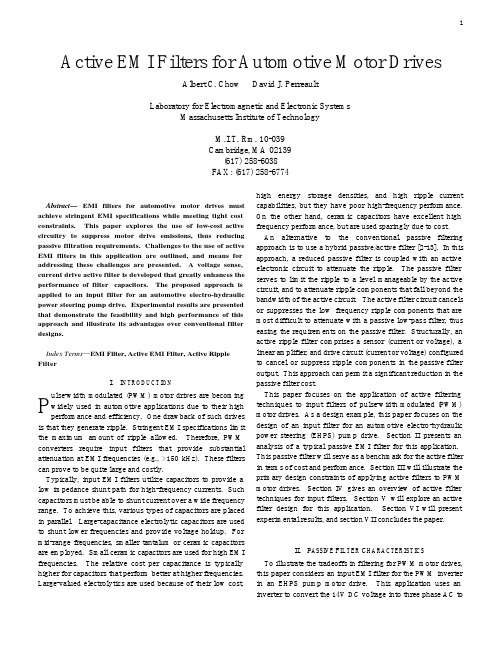
Abstract—EMI filters for automotive motor drives must achieve stringent EMI specifications while meeting tight cost constraints. This paper explores the use of low-cost active circuitry to suppress motor drive emissions, thus reducing passive filtration requirements. Challenges to the use of active EMI filters in this application are outlined, and means for addressing these challenges are presented. A voltage sense, current drive active filter is developed that greatly enhances the performance of filter capacitors. The proposed approach is applied to an input filter for an automotive electro-hydraulic power steering pump drive. Experimental results are presented that demonstrate the feasibility and high performance of this approach and illustrate its advantages over conventional filter designs.Index Terms—EMI Filter, Active EMI Filter, Active Ripple FilterI.I NTRODUCTIONulse-width modulated (PWM) motor drives are becoming widely used in automotive applications due to their high performance and efficiency. One drawback of such drives is that they generate ripple. Stringent EMI specifications limit the maximum amount of ripple allowed. Therefore, PWM converters require input filters that provide substantial attenuation at EMI frequencies (e.g., >150 kHz). These filters can prove to be quite large and costly.Typically, input EMI filters utilize capacitors to provide a low impedance shunt path for high-frequency currents. Such capacitors must be able to shunt current over a wide frequency range. To achieve this, various types of capacitors are placed in parallel. Large-capacitance electrolytic capacitors are used to shunt lower frequencies and provide voltage holdup. For mid-range frequencies, smaller tantalum or ceramic capacitors are employed. Small ceramic capacitors are used for high EMI frequencies. The relative cost per capacitance is typically higher for capacitors that perform better at higher frequencies. Large-valued electrolytics are used because of their low cost, high energy storage densities, and high ripple current capabilities, but they have poor high-frequency performance. On the other hand, ceramic capacitors have excellent high frequency performance, but are used sparingly due to cost.An alternative to the conventional passive filtering approach is to use a hybrid passive/active filter [2-13]. In this approach, a reduced passive filter is coupled with an active electronic circuit to attenuate the ripple. The passive filter serves to limit the ripple to a level manageable by the active circuit, and to attenuate ripple components that fall beyond the bandwidth of the active circuit. The active filter circuit cancels or suppresses the low frequency ripple components that are most difficult to attenuate with a passive low-pass filter, thus easing the requirements on the passive filter. Structurally, an active ripple filter comprises a sensor (current or voltage), a linear amplifier, and drive circuit (current or voltage) configured to cancel or suppress ripple components in the passive filter output. This approach can permit a significant reduction in the passive filter cost.This paper focuses on the application of active filtering techniques to input filters of pulse-width modulated (PWM) motor drives. As a design example, this paper focuses on the design of an input filter for an automotive electro-hydraulic power steering (EHPS) pump drive. Section II presents an analysis of a typical passive EMI filter for this application. This passive filter will serve as a benchmark for the active filter in terms of cost and performance. Section III will illustrate the primary design constraints of applying active filters to PWM motor drives. Section IV gives an overview of active filter techniques for input filters. Section V will explore an active filter design for this application. Section VI will present experimental results, and section VII concludes the paper.II.P ASSIVE F ILTER C HARACTERISTICSTo illustrate the tradeoffs in filtering for PWM motor drives, this paper considers an input EMI filter for the PWM inverter in an EHPS pump motor drive. This application uses an inverter to convert the 14V DC voltage into three phase AC toActive EMI Filters for Automotive Motor DrivesAlbert C. Chow David J. PerreaultLaboratory for Electromagnetic and Electronic SystemsMassachusetts Institute of TechnologyM.I.T. Rm. 10-039Cambridge, MA 02139(617) 258-6038FAX: (617) 258-6774Pdrive a brushless motor for the EHPS system. The electrical motor replaces the belt-drive for a hydraulic fluid pump, and allows for more efficient operation of the power steering system. The inverter has a fundamental switching frequency of 10 KHz and a peak input current of 70 amps.The structure of a typical passive input filter for this application is illustrated in Fig. 11. It uses a modified pi filter structure with a 3900 µF electrolytic capacitor at the input to the inverter and a 22µF ceramic capacitor at the supply interface. Separating the two capacitors are two 3.6 µH inductors providing both common mode and differential mode filtering. In addition to the electrolytic capacitor at the inverter input there is a small ceramic (1nF) capacitor in parallel with it for higher frequencies. The same is true of the large-valued ceramic capacitor (22µF). An approximate cost breakdown of this filter is illustrated in Table 1, based on commercial pricing in quantities of 20002. The high-valued ceramic capacitor costs about the same as the large electrolytic capacitor though it is physically much smaller. This passive filter will serve as a benchmark for performance and cost. Active filter techniques will be explored with the objective of improving filter cost while maintaining filter performance.III.D ESIGN C ONSIDERATIONSIn most automotive a nd commercial applications, cost is a major consideration. Historically, active filter methods have been most widely applied in applications where the need for high performance justifies additional cost. This work seeks a reduction of cost through active filtering while maintaining constant performance.1 The design of Fig. 1 closely approximates one in recent commercial production for this application.2 While this does not reflect automotive pricing scales it is a reasonable measure of relative component costs. We are unable to account for differences in how individual components costs scale to high volume.Based on the cost breakdown of Table 1 alone, any of the major components are reasonable targets for augmentation via active techniques. Power dissipation considerations, however, restrict us to utilizing active techniques in the outer stages of the filter. To understand this, consider the large electrolytic capacitor. The feasibility of applying active circuit techniques to a capacitor is dependent on the ripple current the capacitor must carry. Simulations suggest that this bulk capacitor carries peak ripple current on the order of 40A (worst-case) and up to 15A RMS, making it impractical to augment its performance via active methods. Conversely, the 22µF ceramic capacitor carries a worst-case ripple current of 0.9A (peak-to-peak), making it a more reasonable target for active techniques. The inductors could also be augmented using active techniques. However the topological complexity of doing this (see, e.g., [13]) may make this less desirable from a cost standpoint. Thus, this paper focuses on applying active circuits to replace the outer stage 22µF ceramic filter capacitor.In order for an active filter to be a commercially viable replacement for the capacitor, the entire active filter must cost under $2. The severe cost constraints in this application allow the use of only lower-end, minimal cost transistors, such as the 3904 and 3906. These transistors are standard signal-leveltransistors in a TO-92 package, and have a power dissipationlimit of around a third of a watt. Designing an amplifier to handle the full peak current ripple (0.9A peak) is difficult with such devices, and rapidly becomes cost prohibitive.The outer-stage filter capacitor sees substantial ripple current in this application. This is characteristic of PWM drive filters. In dc/dc converter applications, the fundamental switching frequency is typically in or near the frequency range covered by EMI specifications (e.g., >150 kHz), and hence is greatly attenuated by the inner filter stages. PWM motor drives, however, typically switch at very low frequencies (10 kHz in the example considered here), which are well below the frequency range covered by EMI specifications. Therefore, a significant amount of the fundamental ripple appears at the filter output. That is, it is not cost effective (or required) to filter the fundamental switching frequency and its low-order harmonics, so these components are not greatly attenuated by the inner filter elements and still appear at the outer part of the filter. This is an important factor in design of active filter circuits for this application.The large, low-frequency component in the ripple poses a substantial challenge in the active filter design because of theincreased power dissipation required to attenuate this ripple, which directly translates to an increase in cost. A saving factor lies in typical EMI specifications such as SAE J1113/41. While the majority of the ripple is due to the fundamental switching frequency of the inverter and its low-order harmonics, EMI ripple attenuation is only required from 150 kHz onward. If the active components are able to reject the low-frequency components (< 150 kHz) and operate only on the EMI frequencies, the power-driving requirement on the active filter is greatly reduced. Therefore, with appropriate design an active filter approach is viable in this application. A further constraint is that the active filter circuitry must be powered from the available 14V power supply bus. Other power supply requirements would unacceptably increase the system cost. Given these constraints, design of the active filters for this application is quite interesting and challenging.IV. A CTIVE T ECHNIQUES FOR INPUT FILTERSIn general, active ripple filters are linear amplifier circuits that enhance the performance of passive impedances. The active filter may either increase the effective impedance of a series path or reduce the effective impedance of a shunt path. For example, as illustrated in Fig. 2 (left) a series active f i lter introduces a voltage in series with a noise source, effectively increasing the impedance of that series path to noise currents. Similarly, a shunt active ripple filter is placed in shunt with a noise source, reducing the effective impedance of the shunt path (Fig. 2, right). A variety of filter structures and control methods are possible, but generally conform to one or both of these approaches.Noise suppression control can be achieved through feedforward and/or feedback. Feedforward control relies on a small but precise gain. For a perfect feedforward path gain of unity, the ripple would be entirely cancelled. However, due to gain and phase accuracy limitations in the components, feedforward cancellation alone cannot fully attenuate the ripple. On the other hand, feedback relies on a large but possibly imprecise gain. The feedback gain is directly proportional to the ripple suppression. In other words, the larger the gain the larger the ripple attenuation; an infinite gain would yield zero ripple. Stability considerations limit theachievable feedback suppression. A combination of bothfeedback and feedforward control is also possible.V.A CTIVE F ILTER D ESIGNA.Active Filter TopologyAs previously described, this paper introduces a shunt active filter circuit to replace the output (battery-side) capacitor in the motor drive filter. The active filter reduces the shunt-path impedance at the filter output by enhancing the performance of a small capacitor using a feedback control configuration. A feedback approach was selected because it was found to be less costly to implement a high gain feedback circuit than to implement an amplifier with a precise gain and low phase shift in a feedforward configuration.Capacitor enhancement can be implemented using various means including current-sense/current-drive, voltage-sense/voltage-drive, current-sense/voltage-drive, and current-sense/current-drive [11,12]. A voltage-sense/voltage drive configuration was selected for cost reasons. Although the amplifier design uses a voltage drive, the overall active filter can be thought of as using current injection. The amplifier drives a voltage across a load capacitor, which converts it into an AC current. This strategy is illustrated in F ig. 3 and provides an effective shunt-path impedance Z eq as shown there. Voltage drive enables low-loss injection to be achieved without an additional supply voltage, and voltage sensing is more economically realized than is current sensing for a given circuit gain.Although the active filter is implemented as one multistage amplifier, it is advantageous to break the design into two pieces: the sensing filter and the amplifier (see Fig. 4). The sensing filter, H(s), measures the voltage, and filters it to select which frequencies to pass onto the amplifier and which frequencies to reject. The amplifier, A, merely takes the voltage signal given by the sensing filter, amplifies it, and drives the resulting voltage across the reduced passive capacitor.B.Design of Sensing FilterThe design of the sensing filter proves to be a primary challenge of this system. It determines the power dissipation of the drive stage and sets the closed-loop dynamics. The ideal sensing filter would have a sharp cutoff, essentially goingfrom high attenuation to high gain in less than a decade, rejecting the fundamental (10 kHz) and low-order harmonics, and passing EMI frequencies (>150 kHz). Such a sharp cutoff would require a high order sensing filter, complicating the topology and making it more difficult to attain a stable feedback loop. Loop compensation may be added within the sensing filter to achieve stability, but this again adds complexity and oscillations may occur due to amplifier non-linearities3. Ultimately, amplifier nonidealities make it difficult to use a sensing filter with an order higher than one. Unfortunately, a first-order (high-pass) sensing filter does not provide enough separation between the pass band and stop band. The filter is unable to sufficiently attenuate the 10 KHz signal (to within the power limitations of the amplifier transistors), while still providing adequate gain at 150 KHz and beyond.To overcome these limitations, a low-frequency, low impedance bypass network is placed in parallel with the sensing filter, reducing the low frequency ripple voltage it3 Nonlinearities can cause the loop gain of the feedback system to decrease for certain input magnitudes, driving the system unstable. sees. The network comprises one or more medium-sized electrolytic capacitors. The low cost of electrolytics makes this a viable solution. Electrolytic capacitors have poor performance at higher frequencies, where their ESL and ESR limit their ability to shunt current. By placing an electrolytic capacitor larger than 22 µF in parallel with the active filter, the lower frequency currents, including the 10 KHz fundamental, will be shunted from the a ctive filter (see Fig 5); two 22 µF electrolytic capacitors are used in the prototype system. At higher EMI frequencies, where the electrolytic capacitor ceases to perform well, the active filter takes over and shunts the high-frequency currents. At still higher frequencies, beyond the bandwidth of the active circuit, a small ceramic capacitor serves as the shunt element.C.Design of the AmplifierThe primary functions of the amplifier are to provide the feedback loop gain and to drive the voltage across the capacitor. A three-stage amplifier is chosen for these functions, comprising a gain stage, a buffer stage, and an output stage (Fig. 6). As mentioned previously, the entire amplifier circuit is implemented with inexpensive, low-end transistors. The gain stage (first stage) uses a common emitter configuration. Common emitter amplifiers offer a large input impedance, which is ideal for voltage sensing. The gain of the overall amplifier is determined by active filter requirements. Since the suppression of the current ripple is directly proportional to the feeback loop gain, the design of the amplifier should maximize the gain. However with any feedback system, the tradeoff between gain and stability is theprimary performance limitation. The upper limit on the amountof gain achievable is set by the stability of the system. As mentioned previously, the stability is highly dependent upon the sensing filter. The maximum amount of stable gain can be easily determined by standard feedback loop design techniques (a gain of 150 is used in the prototype). Furthermore, this amplifier configuration is bandwidth limited due to the Miller effect, which multiplies capacitances by the gain of the system. Fortunately, the bandwidth of the circuit (~2MHz) is sufficient for the application.The following two stages, the buffer stage and the output stage, are closely related. The buffer stage is implemented with two emitter followers and the output stage uses a push-pull configuration. The second stage provides large input impedance for the gain stage and biases the output stage. The gain stage has a relatively large output impedance therefore a buffer stage is needed to maintain the gain of the amplifier. The output stage has been designed to minimize DC bias currents and therefore the overall dissipation of the system. A push-pull circuit has no bias current, but it does have a dead zone. In the dead zone the output voltage is zero if the input voltage is within the thermal voltage of the transistor. A smallbias current is passed through both push-pull transistors in order to eliminate the dead zone (class AB). The two transistors are biased with emitter followers, which have the extra benefit of increasing the input impedance to the drive stage. One concern of a push-pull output stage is maintaining bias stability. In this configuration, it is possible for the current to increase with out bound. Placing resistors in the emitters of the push-pull transistors is one solution. The emitter resistors serve provide bias feedback and to limit the amount of current f low. The output stage does not provide any voltage gain. It serves as a voltage buffer and a power gain stage.The voltage-sense/voltage-drive topology, which injects current, has the drawback of increased peak current, which affects the achievable bandwidth of the system. Simulation can facilitate the prediction of the peak current needed. The hybrid system is modeled as a sensing filter with lead compensation, two 22 µF electrolytic capacitors, and an ideal voltage gain driving a load capacitor (see Fig 7). Simulations show that the peak current needed is 500mA. The 3904 and 3906 transistors are not designed to handle these peaks 50B Vcurrents. Fortunately, the 2222 and 2906 can accommodate this current magnitude, cost the same, and have the same packaging. The tradeoff is that the 2222 and 2906 have a lower unity beta bandwidth than the 3904 and 3906. This is due to the larger parasitic capacitances of the 2222 and 2906. Fig. 6 shows the resulting active filter circuit, not including the two 22µF electrolytic, low-frequency, bypass capacitors.The overall active filter yields a substantial cost benefit over the purely passive filter. The active filter effectively replaces the 22µF ceramic capacitor. The total cost of the active filter is $0.70 verses $2.00, the cost of the capacitor (see Table 2). Thecomponent cost is given as US dollars per unit for a quantity of two thousand.VI.E XPERIMENTAL R ESULTSThe test setup of the system used a current noise source. The PWM motor drive can be approximated by a square wave current source, with a duty cycle of 50 percent and a peak current of 15 amps. Standard EMI measurement techniques are followed. A LISN (Line Impedance Stabilization Network) is placed between the filter and the 14 V supply. The LISN passes power frequency signals to the load, while acting as a known impedance at ripple frequencies. The voltage across the 50 ohm LISN resistor is used as the metric for input ripple performance.The performance of the hybrid filter is determined by first taking measurements without the active filter element. Essentially, the only outer-stage filter capacitance is the two medium sized (22µF) electrolytic capacitors. Measurements were then taken with the active filter in operation. Figure 8 illustrates the dramatic improvement in output voltage ripple performance that is achieved through the use of the active circuitry. The spectral measurements confirm the poor performance of the electrolytic capacitors at higher frequencies. The active circuitry provides an additional attenuation over using the electrolytic capacitors alone. Next, a performance comparison is needed between the benchmark passive filter (with the 22 µF ceramic capacitor) and the hybrid/active filter. Relative performance of these circuits is shown in Fig. 9. The performance of the two filters is the same at the higher frequencies. At the lower frequencies the ripple is slightly higher in the hybrid/active filter than the purely passive filter. The slight difference in performance between the two at lower frequencies is acceptable because the SAE EMI specification allows for more ripple at these lower frequencies. Therefore, the active filter allows expensive ceramic capacitors to be replaced with inexpensive electrolytic capacitors (plus active filter) with no degradation in performance. The demonstrated benefit of the proposed approach is that by introducing simple, signal-level active circuitry, one can dramatically reduce the filter cost for the same level of performanceVII.C ONCLUSIONActive ripple filters can effect substantial reductions in power converter input and output filter cost. This paper investigates a hybrid passive/active filter topology that uses a shunt filter approach in a feedback configuration. The desi gn of a sense filter and amplifier suitable for the application are investigated. The experimental results demonstrate the feasibility and high performance of the new approach, and illustrate its potential benefits. It is demonstrated that the proposed approach is most effective in cases where it is desirable to reduce the capacitance cost in the filter. In these cases, a cost reduction of 65% is possible, without impacting ripple performance.A CKNOWLEDGMENTThe authors would like to acknowledge the support for this research provided by the United States Office of Naval Research under grant number N00014-00-1-0381, and by the member companies of the MIT/Industry Consortium on Advanced Automotive Electrical/Electronic Components and Systems. In addition the authors would like to give special thanks to Mr. Philip Desmond of Motorola AIEG and Mr. Peter Miller of Ricardo for their valuable input in this project.R EFERENCES[1]T.K. Phelps and W.S. Tate, “Optimizing Passive Input FilterDesign,” Proceedings of Powercon 6, May 1979, pp. G1-1 - G1-10.[2]M. Zhu, D.J. Perreault, V. Caliskan, T.C. Neugebauer, S.Guttowski, and J.G. Kassakian, “Design and Evaluation of anActive Ripple Filter with Rogowski-Coil Current Sensing,” IEEEPESC Record, Vol. 2, 1999, pp. 874 -880.[3]S. Feng , W. A. Sander, and T. Wilson, “Small-CapacitanceNondissipative Ripple Filters for DC Supplies,” IEEE Transactions on Magnetics, Vol. 6, No. 1, March 1970, pp. 137-142.[4] D.C. Hamill “An Efficient Active Ripple Filter for Use in DC-DCConversion,” IEEE Transactions on Aerospace and ElectronicSystems, Vol. 32, No. 3, July 1996, pp. 1077-1084.[5]N.K. Poon, J.C.P. Liu, C.K. Tse, and M.H Pong, “Techniques forInput Ripple Current Cancellation: Classification andImplementation,” IEEE Transactions on Power Electronics, Vol.15, No. 6, November 2000, pp. 1144-1152.[6]J. Walker, “Designing Practical and Effective Active EMI filters,”Proceedings of Powercon 11, 1984, I-3 pp. 1-8.Quantity Description Cost ($)/Unit2 Small Ceramic (pF) 0.041 0.22 µF Ceramic 0.072 0.47 µF Ceramic 0.112 22 µF Electrolytic BypassCapacitor0.045 Transistors 0.05Table 2: C ost break down of the components in the hybrid filter. The cost per unit is based on estimated cost attained for quantities of 2000.[7]L.E. LaWhite and M.F. Schlecht, “Active Filters for 1 MHzPower Circuits With Strict Input/Output Ripple Requirements,”IEEE Transactions on Power Electronics, Vol. PE-2, No.4,October 1987, pp. 282-290.[8]T. Farkas and M.F. Schlecht, “Viability of Active EMI Filters forUtility Applications,” IEEE Transactions on Power Electronics,Vol. 9, No. 3, May 1994, pp. 328-337.[9]M.S. Moon and B.H. Cho, “Novel Active Ripple Filter for theSolar Array Shunt Switching Unit,” Journal of Propulsion andPower, Vol. 12, No. 1, January-February 1996, pp. 78-82. [10]P. Midya and P.T. Krein, “Feed-forward Active Filter for OutputRipple Cancellation,” International Journal Electronics, Vol. 77,No. 5, pp. 805-818.[11]L.R. Casey, A. Goldberg, and M.F. Schlecht, “Issues Regarding theCapacitance of 1-10 MHz Transformers,” Proceedings IEEEAPEC, 1988, pp. 352 –359.[12] A. Goldberg, J.G. Kassakian, and M.F. Schlecht, “Issues Related to1-10-MHZ Transformer Design,” IEEE Transactions on PowerElectronics, Vol. 4, No. 1, January 1989, pp. 113-123.[13] A.C. Chow, D.J. Perreault, “Design and evaluation of an activeripple filter using voltage injection,” IEEE PESC Record, Vol.1, 2001, pp. 390 –397.。

使用说明书 OPERATIONAL MANUAL版本:AVersion:A电液转换器Elec-hydr. ConverterVOITH TURBO GMBH & CO.KGI/H ConverterType DSG-B03212Type DSG-B07212 Instruction ManualVersion 1.005 / 03cet - Ochs Voith Turbo GmbH & Co, KG Page: 1 / 20Should you have any questions concerning the I/H converter, please contactthe Service Department of the product group Electronic Drive Systems,Voith Turbo GmbH & Co. KG, Crailsheim, indicatingarticle number and serial number of the I/H converter.Voith Turbo GmbH & Co. KGP.O. Box 15 55D-74555 CrailsheimSwitchboard:++49 – 7951 / 32 - 0Fax:++49 – 7951 / 32 – 500Service department of the product groupElectronic Drive SystemsDirect dial:++49 – 7951 / 32 - 470Direct fax: ++49 – 7951 / 32 - 605E-mail: turcon@Address for goods supplied:Voith Turbo GmbH & Co. KGDept. ceVoithstr. 1D-74564 CrailsheimThis instruction manual describes the technical condition of theI/H converter on delivery from May 2003.Any modifications following the delivery are not considered in this operating manual.Ó Voith Turbo GmbH & Co. KG 2003This instruction manual is protected by copyright.It may not be reproduced or translated in any form or by anymeans (mechanical or electronic) or submitted tothird parties, without the publisher’s written approval.Issued:03-05Order No.: 3.626- 018861 enVersion: 1.00Printed in Germany05 / 03cet - Ochs Voith Turbo GmbH & Co, KG Page: 2 / 20Contents1.Technical data2.Safety Information2.1Definition of notes and symbols2.2Proper use2.3Important notes2.4Warranty3.Functional Description3.1Mechanical design3.2Operating characteristics4.Packing, Storage and Transport5.Installation5.1Mounting5.2Hydraulic connection5.3Electric connection6. Commissioning6.1Test run6.2Parameter setting7. Operation7.1 Operation with manual operation knob7.2 Operation wit set signal7.3 Trouble shooting and remedial action8.Maintenance and Repair9.Shutdown10.Outline drawing with Wiring Diagram11.Annex05 / 03cet - Ochs Voith Turbo GmbH & Co, KG Page: 3 / 201.Technical DataAmbient conditions:Ambient temperature for storage-40 °C ... +90 °CAmbient temperature:- Normal operation-20 °C ... +85 °C- Potentially explosive atmos.-20 °C ... +60 °CExplosion protection EEx d IICTemperature class T4, at Ta = -20 °C ... +60 °CDevice group IICategory2GProtection IP 65 to EN 60529suitable for internal installation in industrial airElectric data:Supply voltage24 VDC ± 10%Power consumption approx. 0.7 Amax. 3 A, for t < 1 secSetpoint input w = 0/4...20 mAinput resistor 25 Ohmwith suppressor circuit05 / 03cet - Ochs Voith Turbo GmbH & Co, KG Page: 4 / 20Hydraulic data:Input pressure P in min 1.5 bar more than P A max Input pressure P in max see tablePressure fluid mineral oil or hydraulic oil(hardly combustible fluids onrequest)Viscosity pressure fluid ISO VG 32... ISO VG 48 toDIN 51519Temperature pressure fluid:+10 °C...+60 °COil purity recommended purity class:To NAS1638 class 7To ISO4406 class -/16/13 Leakage£ 5 l/minDSG-BXX212TypeB03...B07... Output pressure regulating rangeP A[bar]0..30..7 Input pressureP(max) [bar]4040Flow rate line P ® AQ1[l/min]at D P = 1 bar1717Flow rate line A ® TQ2[l/min]at D P = 1 bar1818Regulating range approx.P A max [bar]at setpoint w = 20 mA1..3 5..7Regulating range approx.P A min [bar] at setpoint w = 4 mA 0..0.80..21..31.5..5The regulating range of P A min depends on the set pressure P A max.The regulating range of P A min indicated in the first line refers to the minimumadjustable pressure P A max .Mechanical data:Dimensions, fitting see chapter 10Hydraulic connection see chapter 10Mounting position see chapter 10Sealing material FPMWeight approx. 12 kg05 / 03cet - Ochs Voith Turbo GmbH & Co, KG Page: 5 / 202.Safety Information2.1Definition of notes and symbolsDanger !This symbol signals an imminent danger to the life and health of individuals.If this note is not observed, injury to health and even mostserious injuries may be the consequence.Warning !This symbol signals a harmful situation.If this note is not observed, the product may be damaged.Note !This symbol refers to proper handling of the product. It does not refer toor indicate a dangerous situation.2.2Proper useThe I/H converter serves to transform an electric set signalinto a related hydraulic output pressure reduced to feed-in pressure. Thisallows, for example, adjusting control pistons at hydraulic cylinders whichare used to position the valves of steam turbines.The I/H converter is suitable for usage in potentially explosiveatmospheres according to the explosion protection mentioned inchapter 1.2.3Important notesThe following notes refer to the entire instruction manual and have to beobserved in addition to the individual notes.Accident prevention·In any case observe the relevant standards and regulations when connecting an I/H converter in ex-design.·Improper use may cause operating agent under pressure to leak at the sealing surfaces. There is a risk of fire around hot components.·Isolate the hydraulic supply prior to working on the I/H converter.05 / 03cet - Ochs Voith Turbo GmbH & Co, KG Page: 6 / 20·Failure of electric power or disturbance of the control electronics integrated in the I/H converter may cause strong variations of theoutput pressure when operating the I/H converter. Thus e.g. thepiston rod of a hydraulic cylinder may move uncontrolled, causing danger to individuals or equipment.·During operation, the outer surfaces of the I/H converter may heat up due to the pressure fluid. Contact may cause skin burns. Make sureto cool down the I/H converter prior to working on it.·Electrical components are installed in the I/H converter. These components can be destroyed by e.g. welding in its surrounding.Therefore make sure to disconnect all electric connections prior toelectrical weldings in the surrounding of the I/H converter.Environment protection·During mounting, dismounting or improper use of the I/H converter pressure fluid may leak out. Operating agent reaching the sewagesystem or the open soil, causes severe environmental damages.Leaking pressure fluid has to be collected and deposited inaccordance with the national legal regulations.Instruction manual·The instruction manual contains important information for proper handling of the I/H converter. Prior to installation and commissioningof the I/H converter, read the manual carefully and make sure it iscompletely understood.·Keep this manual in a location convenient to the operating staff.·In addition to this operating manual: Have the relevant regulations for prevention of accidents and environmental protection available andobserve these.05 / 03cet - Ochs Voith Turbo GmbH & Co, KG Page: 7 / 2005 / 03cet - Ochs Voith Turbo GmbH & Co, KGPage: 8 / 20Staff qualification· Only trained and instructed staff is allowed to perform any work on theI/H converter. This personnel has to be trained and authorized to mount I/H converters professionally.· Installation, commissioning and operation have to be performed by anelectronic expert with experiences and knowledge in explosion protection.Constructional modifications· Mounting and constructional modifications are not permitted.· The screwing of the cable inlet is secured against distortion. Do notdistort or loosen the screwing.2.4WarrantyThe terms and conditions mentioned in the General Conditions of Sale of Voith Turbo GmbH & Co. KG, Crailsheim, are applicable.Warranty claims are excluded, if these are due to one or several of the following causes:· Improper transportation, storage, mounting, set-up, commissioningand operation of the I/H converter.· Not observing the safety instructions and guidelines included in thisinstruction manual.· Use of spare parts not approved byVoith Turbo GmbH & Co. KG, Crailsheim.Repair works on the I/H converter are to be performed or approved by Voith Turbo GmbH & Co. KG, Crailsheim.05 / 03cet - Ochs Voith Turbo GmbH & Co, KGPage: 9 / 203.Function3.1DesignFig. 3.1.11 – Control magnet VRMP - Input pressure2 – Tappet for power transmission P A - Output signal pressure3 - Potentiometer X0 und X14 – Manual operation knob T 1- Tank return line5 – Electric connection T 2- Tank return line int. leakage6 – Control housing F Mag - Magnetic force7 – Control piston F Hyd - Hydraulic force8 - CoverF Fed- Spring force9 - Control spring3.2 Operatingcharacteristics(see fig. 3.1.1)A set signal w = 0/4...20 mA generates a magnetic force F Mag in theVRM, the limits of which can be adjusted by means of the X0 and X1potentiometers and which is then transmitted onto the control piston viatappet.The hydraulic force F Hyd being proportional to the output signal pressureP A acts against this force.In the case of the two forces being equal, the control piston is positionedin the “hydraulic center” as shown in fig. 3.1.1 and the output signalpressure P A corresponds to the set signal. In the “hydraulic center“position the control piston performs minimum oscillating movements inthe area of the guiding edges P®P A and P A®T , in order to keep theoutput pressure P A on the value set by F Mag.When increasing the set signal and thus F Mag from this condition, thecontrol piston position changes and thus connects the output pressure P Ato the feed pressure P in and blocks P A towards the tank return line T1.Now the pressure P A will increase until the control piston returns to the”hydraulic center“ and P A corresponds to the new set signal.The spring force F Fed of the control spring generates a force-offset inorder to guarantee the I/H converter function for output pressures ofapprox. 0 bar, too.The internal leakage is fed back via tank return line T2.Function of manual operation knobThe control magnet of the I/H converter is provided with a manualoperation knob, by means of which an adjustable spring force can be setinstead of the magnetic force F Mag . This spring force affects the controlpiston via magnet armature and tappet. The hydraulic force F Hyd , beingproportional to the output signal pressure P A also acts against this springforce here. Thus adjustment of output pressure is possible withoutelectric connection.4.Packing, Storage and TransportPackingThe I/H converter is delivered in a special packing.The openings for the hydraulic connections are sealed with plugs toprevent penetration of impurities and humidity.Storage and preservingThe outer surfaces of the I/H converter are protected by means of apreserving surface coat.The internal parts are preserved by oil.Within Europe the anticorrosion protection is sufficient for approx. 8months in industrial air, presuming storage of the I/H converter in a drylocation.In case the I/H converter is supposed to be stored for a longer period oftime, special precautions will have to be taken.In each specific case, these precautions have to be agreed withVoith Turbo GmbH & Co, KG, Crailsheim.The storage ambient conditions have to be within the limits as indicatedin chapter 1.TransportImproper transport may cause personal injuries and damages toproperty.Pack the I/H converter in a way that prevents housing damages duringtransport. In particular make sure that no compulsive forces affect theelectric cable fitting and the electric feed in cable are not kinked ordamaged. Do not hold the I/H converter at the electric feed in cable fortransport.5.Installation·Improper installation of the I/H converter may cause malfunctions and premature failure of the operation of the I/H converter.·Cleanliness is imperative during installation an connection. Prevent that any impurities ( dust, metal chips etc.) can get into the I/Hconverter or pipe system which may cause damage to the I/Hconverter.Cover and protect the I/H converter and in particular the electric linesduring construction time.5.1MountingPerform any work on the I/H converter only when it is in deenergizedcondition and with switched off oil supply system.Protect oil and power supply against unintentional switching-on duringmounting.Install the I/H converter in accordance with the permissible installationposition as shown in chapter 10.Recommended fastening bolts:2 pieces hexagonal screws M10, strength category 8.8.tightening torque MA=35 Nm, thread slightly oiled.Select screw length according to mounting situation.connection5.2 HydraulicThe hydraulic connection on the I/H converter is made by means ofconnection bores at its bottom. The connection flange is sealed witho-rings. Please refer to chapter 10 for position and dimensions of theconnections.Surface roughness of connecting flange:Ra = 1.6 m m, Rmax = 6.3 m mOnly pressure-less return of the operating medium through the return lineT2 to the tank, ensures proper work of the I/H converter.In practise the tank lines for the connections T1 and T2 are joinedtogether and laid downgrade towards the tank in one common pipe line.Requirements to this pipe line:Nominal size 20 mm or bigger for I/H converters with an output pressureup to 10 bar.Nominal size 30 mm or bigger for I/H converters with an output pressureof more than 10 bar.Observe the correct pressure range when selecting pipes, hoses,screwings and flanges.Immediately replace damaged pipes and hose lines.When assembling the pipe lines, ensure that it is fastened to fixedstructures, free from vibration and not to moving equipment. Temperaturevariations of the piping (thus alterations in length) must not applyconstraining forces to the I/H converter.Clean pipe lines from dirt, cinder, sand, chips etc. prior to installation.Pickle or flush welded pipes.Clean and flush carefully all pipe and hose lines prior to attaching theI/H converter.=> For flushing, a flushing plate (Art. No. 43.8565.10) is available.See chapter 11.=> To connect the I/H converter to the piping system an adapter (Art. no.43.9300.11) is available. See chapter 11.·Residual oil may leak when removing the plug (max. 0,1 l). Collect the oil in a suitable container and deposit it properly.·Do not use fibrous or hardening sealing compounds, such as e.g.hemp or mastic to seal the connections and screwings.5.3Electric connectionThe electric system has to be connected in accordance with electricalengineering standards and legal regulations of the manufacturingcountry. The works have to be performed by an electric specialist withexperience and knowledge in explosion protection.When connecting the I/H converter within the explosion hazardous area ,the electric feed in line have to be connected in housings according toprotection type EN 50014, section 1.2.When connecting customer´s lines, avoid parallel run of the I/H converterlines with the lines of current converter assemblies.The customer`s signals and supply lines running to the I/H convertermust be screened.Please refer to chapter 10 for the wiring diagram.missioningThe I/H converter was adjusted and tested at Voith Turbo’s works bymeans of the potentiometers X0 and X1. The test result is documented inan attached test certificate.The potentiometers are provided with a protective cap to avoidunintentional maladjustment and impurities.6.1Test runMake sure that pipe lines and hydraulic system are cleaned prior toperforming a test run. The operating fluid has to be in accordance withthe purity class as indicated in chapter 1. Do not flush or clean thepressure fluid with the I/H converter being hydraulically connected.Operation of the I/H converter with contaminated pressure fluid is notpermitted, the I/H converter may be damaged.·Check the line mounting, connection and flow direction to and on the I/H converter.·Check the electric connection.·Switch on the 24 VDC power supply.·Switch on the oil supply and check input pressure.The minimum input pressure has to be 1.5 bar more than the maximumoutput pressure required at 20 mA.·Set the signal w = 0/4.. 20mA and check output pressure.During the test run, check all hydraulic connections for leakages. Incase of leakage, immediately switch off the hydraulic supply andeliminate leakages.6.2Parameter settingDue to unintentional maladjustment of the parameters or changedoperating conditions, new setting of one or both parameters may becomenecessary.We recommend to document adjustment of the parameters as well as theset values.The parameters are adjusted by means of potentiometers X0 and X1.Please refer to chapter 10 for the position of the potentiometers.Potentiometer effects:X0-With help of potentiometer X0 the minimum output pressureP A min is adjusted at a setpoint of 0 mA or 4 mA.Pressure increase by turning the potentiometer clockwise.X1-With help of potentiometer X1 the maximum output pressureP A max is adjusted at a setpoint of 20 mA.Pressure increase by turning the potentiometer clockwiseX1 should be adjusted before X0.The X1- adjustment influences the adjustment of X0.Manufacturer-provided adjustments:At the works, the I/H converter has been adjusted as indicated in theorder.7.Operation7.1 Operation with manual knobOperation with manually controlled rotary knob is possible without electricenergy.On operation with manually actuated rotary knob, uncontrolled strokemovements of the hydraulic components controlled by the I/H converteroutput might occur due to the increase in the output signal pressure.Manual operation is only possible when the circlip is removed from themanual operation knob.On completion of operation with manual operation knob, move themanual operation knob in its final position by turning it counter clockwiseand pushing in the circlip to its final position.·Remove the circlip.·Slowly turn the manual operation knob clockwise and observe the output pressure.Effective direction: Output pressure increase by clockwise rotation.7.2Operation with set signalWhen the supply voltage is switched on, the output signal pressure canbe adjusted continuously by the set signal 0/4...20 mA within the limitsset by the potentiometers X0 und X1.7.3Trouble shooting and remedial actionPrior to all works, make sure that the I/H converter was commissionedaccording to chapters 5 and 6.Malfunction: Pressure variationsThe output signal pressure P A may vary now and then orperiodically with low or high frequency and amplitude.Cause: 1. air inclusions in the hydraulic component2. low or considerably varying input pressure.3. dirt particles in the hydraulic component4. pressure on return lineRemedy: 1.On first commissioning air inclusions in the VRM may causepressure variations. Due to periodic setpoint changes(approx. 0.5 Hz) of approx. +/- 6 mA, the air will escape outof the VRM after some minutes causing the hydraulicdamping to become effective.2. Under load and in particular in case of higher outputsignal pressure, a lower input pressure may lead topressure variations.Increase and / or stabilize the input pressure by takingappropriate measures (e.g. accumulator). See also chapter1.3. Contaminated pressure fluid results in increased friction atthe control piston, thus causing hysteresis and pressurevariations.Open hydraulic component and clean the inner elements. Incase of damaged surfaces and guiding edges replace theI/H converter.4. The dimensions of the return line have to be sufficient.In case of additional consumers of the output pressureconnected to this line, make sure they do not create anypressure in the return line. See also chapter 5.2.Malfunction:Output pressure PA ® 0 bar or ® P (input pressure)Due to a defective control valve VRM or blockage of thecontrol piston the output pressure may fall to 0 bar orincrease to the input pressure.Remedy:The function of the hydraulic component can be checked using the manually controlled knob with the supply voltage beingswitched off. See chapter 7.1.If the output pressure cannot be adjusted manually, the controlpiston, e.g., may be blocked by particles.Open hydraulic component and clean inner parts.If the surfaces and guiding lines are damaged, exchangethe I/H converter.Should output pressure adjustment be possible with manualoperation knob, but not with the control magnet, the controlmagnet VRM is defective.Repairs on the control magnet VRM are not allowed, otherwiseexplosion protection is no longer guaranteed.Replace any defective I/H converter completely.8.Maintenance and RepairFor a trouble-free and reliable operation of the I/H converter, it isnecessary to perform inspection, maintenance and repair work incertain intervals.Routine inspectionCheck the pipes, screw connections and connections on theI/H converter for leakage, impurities and damage.Eliminate any leakage, impurity and damage noticed, if required, duringappropriate operating modes.Monitor the control behavior of the I/H converter for any changes.Analyse and eliminate the causes, if required, during appropriateoperating modes.Inspection after approx. 740 operating hours / max. 1 monthTake an oil sample from the oil tank and analyse it for solid andsuspended matters, water content, shadings and air bubbles.Analyse oil purity of the oil sample. Clean or exchange the oil, ifrequired, in an appropriate operating mode.Inspection after approx. 8000 operating hours / max. 1 yearTake an oil sample from the oil tank and analyse it chemically.If required, clean or change the oil during an appropriate operating mode.Check and retighten, if necessary, the electric connections of the I/Hconverter.9.ShutdownIf the I/H converter is switched off for reasons of repair, inspection orunit shutdown, switch off the oil supply system and relieve all pressurereservoirs, if effective. Switch off the 24 VDC supply voltage andremove the lines as well as piping and hose connections. Doing so, anconsiderable oil quantity may leak out. Collect the oil in a suitablecontainer and deposit it properly. Close all holes. Now clean and packthe I/H converter.DisposalIn the event of disposal of the I/H converter, observe the local applicableregulations regarding the environmental protection. The I/H converteressentially contains steel, copper, synthetic materials, electroniccomponents and residual oil.Instruction Manual I/H Converter DSG-B03212I/H Converter DSG-B0721205 / 03cet - OchsVoith Turbo GmbH & Co, KG Page: 19 / 203.626 - 018861 en D – 74564 Crailsheim 10.Outline and Wiring DiagramInstruction ManualI/H Converter DSG-B03212I/H Converter DSG-B07212 11.AnnexFlushing plate43.8565.10Adapter plate43.9300.1105 / 03cet - Ochs Voith Turbo GmbH & Co, KG Page: 20 / 20 3.626 - 018861 en D – 74564 Crailsheim。

BUCKET MOTION TIMES Raising time 8.4 sec Lowering time 4.0 sec Dumping time1.8 secCAPACITIESTramming capacity 14 000 kg Break out force, lift 28 082 kg Break out force, tilt24 574 kg Standard bucket 5.4 m³SPEEDS FORWARD & REVERSE (LEVEL/LOADED)1st gear 4.0 km/h 2nd gear 7.1 km/h3rd gear 12.1 km/h 4th gear20.5 km/hOPERATING WEIGHTS T otal operating weight 38 500 kg Front axle 16 200 kg Rear axle22 300 kgLOADED WEIGHTS T otal loaded weight 52 500 kg Front axle 38 000 kg Rear axle14 500 kgThe LH514E is an electrically-driven loader for underground hard rock loading and haulingapplications, with a tramming capacity of 14 metric tons and a payload-to-own-weight ratio that’s best in class.The LH514E is a game changer compared to traditional diesel-powered underground loaders. The LH514E offers a possibility to select a loader equipped with an electric motor emitting zero diesel emissions, and significantly less noise, vibrations and heat than diesel equipment. The loader is a strong package of pure power, delivering high breakout forces, high tramming speeds, and increased acceleration. The high capacity, unique bucket filling design and rapid cycle times mean you can move more material faster – at a lower cost per tonne.Operator efficiency and safety are always a priority in underground LHDs, and the LH514E delivers there, too. Good ergonomics and responsive controls maximize efficiency.Advantages– Zero diesel emissions from the electric motor improves working environment– Small turning radius enables easy navigation and optimized envelope size– High power-to-weight ratio ensures faster cycle times – Sandvik Intelligent Control system offers a user-friendly interface with vehicle parameters for rapid fault-finding– Quick and easy access for ground-level service and maintenance optimizes uptimeTRANSMISSIONPower shift transmission with modulation.Dana 6422, electrical gear shift control, four gears forward and reverse.CONVERTERDana C8672-70AXLESFront axle, spring applied hydraulic operated brakes. Fixed.Kessler D106,limited slip differentials.Rear axle, spring applied hydraulic operated brakes. Oscillating ± 8°.Kessler D106,limited slip differentials.POWER TRAINELECTRIC MOTOR Three phase squirrel-cage drive motor VEM Drive motor output 132 kW Drive motor voltage 1 000 V Drive motor frequency 50 Hz Drive motor speed1 500 rpm Drive motor insulation class F Drive motor degree of protectionIP 55Three phase squirrel-cage pump motor VEM Pump motor output 45 kW Pump motor voltage 900 V Pump motor freguency 50 Hz Pump motor speed1500 rpm Pump motor insulation class FPump motor degree of protectionIP 55Three phase squirrel-cage fan motor VEM, 2 pcs Fan motor output 1.5 kW Fan motor voltage 400 V Fan motor frequency 50 Hz Fan motor speed3 000 rpm Fan motor insulation class FT otal electric power180 kWTIRESTire size (Tires are application approved. Brand and type subject to availability.)26,5x25 L5S 36 plyREQUIREMENTS AND COMPLIANCECompliance with 2006/95/EC Low voltage directiveCompliance with 2004/108/EC Electromagnetic compatibility directiveCompliance with 2006/42/EC Machinery directive (Equipment for EU area, achieved with relevant options)Design based on EN 1889-1. Machines for underground mines. Mobile machines working underground. Safety. Part 1: Rubber tyred vehicles.Design based on MDG 15. Guideline for mobile and transportable equipment for use in mines. (Equipment for Australia, achieved with relevant options)Electrical system based on IEC 60204-1. Safety of machinery – Electrical equipment of machines – Part 1: General requirements CONTAINS FLOURINATED GREENHOUSE GASES (closed cabin option)Refrigerant R134a under pressure max 38 bar/550 PSI:Filled weight: 2,0 kg CO2e: 2,860 tons GWP: 1430Information based on the F Gas Regulation (EU) No 517/2016OPERATOR’S COMPARTMENTCABIN (Cabin option replaces the standard canopy)ROPS certification according to EN ISO 3471FOPS certification according to EN ISO 3449Sealed, air conditioned, over pressurized, noise suppressed closed cabinSound absorbent material to reduce noise Laminated glass windowsCabin mounted on rubber mounts to the frame to reduce vibrationsAir conditioning unit located outside the cabin to reduce noise inside the cabinCyclone pre-filter for A/C device Adjustable joysticksNo high pressure hoses in the operator’s compartment Inclinometers to indicate operating angle Emergency exitFloor washable with water to reduce dustThree-point contact access system with replaceable and colour coded handles and steps 12 V outputRemote circuit breaker switchOPERATIONAL CONDITIONS AND LIMITS Environmental temperature From -20 °C to +50 °CStandard operating altitudeWith standard unit from -1500 m to + 2000 m at 25 °CTS3-LH514E-20/ENG/METRIC2 / 9CONTROL SYSTEM, DASHBOARD AND DISPLAYS Sandvik Intelligent Control systemCritical warnings and alarms displayed as text and with light Instrument panel with 5.7” display, adjustable contrast and brightness. Illuminated switches,My Sandvik Digital Services Knowledge Box™ on-board hardwareSTEERING HYDRAULICSFull hydraulic, centre-pointarticulation, power steering with two double acting cylinders. Steering lock.Steering controlled by electric joystick.Steering main valve Open center type, LS controlledSteering hydraulic cylinders 100 mm, 2 pcs Steering pumpPiston type Steering and servo hydraulic pumpsPiston typeBRAKESService brakes are spring applied; hydraulically operated multidisc wet brakes on all wheels. Two independent circuits: one for the front and one for the rear axle. Service brakes also function as an emergency and parking brake. Brake system performance complies with requirements of EN ISO 3450, AS2958.1 and SABS 1589.Neutral brakeAutomatic brake activation system, ABA Electrically driven emergency brake release pumpBrake oil tank capacity 70 lFRAMEREAR AND FRONT FRAMEHigh strength structure with optimized material thicknesses. Reduced own weight for higher overall hauling capacity and long structural lifetime. Welded steel construction.Central hinge with adjustable upper bearingRear tanks are bolted to frame, hydraulic tank and cabin base are both bolted and welded to frame Automatic central lubricationCANOPY (Standard)ROPS certification according to EN ISO 3471FOPS certification according to EN ISO 3449Adjustable joysticksNo high pressure hoses in the operator’s compartment Inclinometers to indicate operating angle Emergency exitFloor washable with water to reduce dustThree-point contact access system with replaceable and colour coded handles and steps 12 V outputRemote circuit breaker switchHYDRAULICSElectrical filling pump for hydraulic oilDoor interlock for brakes and boom, bucket, and steering hydraulics Oil cooler for hydraulic and transmission oil with capability up to 52°C ambient temperature ORFS fittingsMSHA approved hosesHydraulic oil tank capacity 320 l Sight glass for oil level, 2 pcsBUCKET HYDRAULICSThe oil flow from steering hydraulic pump is directed to bucket hydraulics when steering is not used.Joystick bucket and boom control (electric), equipped with piston pump that delivers oil to the bucket hydraulic main valve.Boom system Z-linkLift cylinders 160 mm, 2 pcs Dump cylinder200 mm, 1 pc Main valveOpen center typePump for bucket hydraulicsPiston type, LS controlledOPERATOR’S SEAT Low frequency suspension Standard Height adjustment Standard Adjustment according to the operator’s weight Standard Padded and adjustable arm rests Standard Two-point seat beltStandardAdjustable lumbar support With cabin option only Selectable damping With cabin option only Fore-aft isolationWith cabin option onlyTS3-LH514E-20/ENG/METRIC3 / 9DOCUMENTATIONSTANDARD MANUALS Operator’s Manual English and other EU languages Maintenance Manual English and other EU languages Parts Manual English Service and Repair ManualEnglish, RussianT oolMan 2 x USB stick in pdf format, includes all the manuals DecalsEnglish, Swedish, RussianOPTIONSSafety cabin, 2-point seatbelt, corner light, ROPS/FOPS and air conditioning unit.Cabin lift kit (150 mm)Disabled 4th gear (mandatory in EU)Line of sight radio remote control (HBC, CAN)Fire suppression system ANSUL, 2 tanks, 8 nozzles (CE), including auto shutdown (not for automation)Fire suppression system ANSUL, 2 tanks, 8 nozzles (CE), Checkfire, including auto shutdown Safety railsEmergency steering (CE)AutoMine ® Loading Onboard PackageAutoMine ® Loading readiness Electric motor 132 kW 660V/50Hz Supply box (IT)Supply box (TNS)Round cable, NEXANS RHEYCORD(RTS), 4x50 mm2, 330 m (1000V)Round cable, NEXANS RHEYCORD(RTS), 4x70 mm2, 280 m (660V)1000VAC 340m KA certified trailing cable (340m 4x50) for China 1000VAC 280m KA certified trailing cable (280m 4x50) for China 660VAC 250m KA certified trailing cable (250m 4x70) for China VICTOR plug for supply box Monitoring camera system Additional cabin heater element for air conditioningCover grills for lamps Spare rim 22.00-25/3.0 (for tires 26.5-25)Tyres 29.5x25 VSDTBoom suspension (ride control)Wiggins quick filling set for oils Integrated weighing systemT owing kit (incl. emergency steering hydraulic pump)CE Declaration of conformityAccordance with KA requirements for Chinese marketINCLUDED SAFETY FEATURESFIRE SAFETYPortable fire extinguisher 12 kg (CE)ENERGY ISOLATIONLockable main switch, ground level accessEmergency stop push buttons according to EN ISO 13850: 1 pc in cabin, 2 pcs in rearAutomatic discharge for pressure accumulators (brake system and pilot circuit)Frame articulation locking device Mechanical boom locking device Wheel chocks and bracketsELECTRICAL EQUIPMENTMAIN COMPONENTS Batteries 2 x 12 V, 56 Ah, Gelled-electrolyte typeDriving lights LED lights:4 pcs in front 4 pcs in rear 4 pcs in cabinWorking lightsLED light, 1 pc under boom Parking, brake and indicator (blinkers) lights LED lights:2 pcs in front, LED lights 2 pcs in rear, LED lightsControl system 5,7’’ color display, 6 modules, inbuilt system diagnosticsReverse alarm (CE)Flashing beaconElectronically controlled cable reeling Cable anchoring unit Cable shock absorberTS3-LH514E-20/ENG/METRIC4 / 9Loaded Percent grade 0.0 2.0 4.0 6.08.010.012.514.317.0Ratio1:121:101:81:71st gear (km/h) 4.03.93.83.83.7 3.63.43.33.12nd gear (km(h)7.16.86.66.25.75.24.4 3.9 3.33rd gear (km/h)12.111.29.88.0 6.34th gear (km/h)20.515.610.2GRADE PERFORMANCE AC 132 kW Empty Percent grade 0.0 2. 0 4.0 6.08.010.012.514.317.0Ratio1:121:101:81:71st gear (km/h) 4.14.03.93.83.8 3.73.63.63.52nd gear (km(h)7.17.06.86.66.36.05.65.2 4.63rd gear (km/h)12.311.711.09.98.67.35.84th gear (km/h)21.318.614.410.6TS3-LH514E-20/ENG/METRIC5 / 9DIMENSIONS WITH 5.4m3 GET BUCKET (STANDARD)The dimensions are indicative onlyTS3-LH514E-20/ENG/METRIC 6 / 9DIMENSIONSStandardBucket alternatives (m³) 4.6 m³ 5.0 m³ 5.4 m³ 6.2 m³7.0 m³Material broken density (kg/m³)max. 3200 kg/m³max. 2900 kg/m³max. 2600 kg/m³max. 2200 kg/m³max. 1900 kg/m³Lip plate type GET GET GET GET GETL1 (mm)1107511193113091147911494L2 (mm)1080010881109601107711087L3 (mm)1040210578105781070610719L4 (mm)32673348342735442708L5 (mm)18001800180018001800L6 (mm)18501850185018501850L7 (mm)38833883388338833883L8 (mm)24082502259527302742L9 (mm)30103128324334133429L10 (mm)26902770284829622971H1, CC517 (mm)25452545254525452545H1, OC410 (mm)25592559255925592559H2 (mm)19131913191319131913H3 (mm)425425425425425H4 (mm) 425425425425425H5 (mm)850850850850850H6 (mm)10701148114813351344H7 (mm)15021588167317901808H8 (mm)26642596252324202411H9 (mm)36993699369936993700H10 (mm)40804080408040804080H11 (mm)51895277536354895494W1 (mm)28972897289728973098W2 (mm)27662766276627663066W3 (mm)25812581258125812581W4 (mm)28192819281928192819A1 10°10°10°10°10°A242.5°42.5°42.5°42.5°42.5°R1, left turn (mm)31553155315531553155R2, left turn (mm)68606898693569927123T, left turn (mm)46294667470447324892R1, right turn (mm)33623362336233623362R2, right turn (mm)68606898693569927123T, right turn (mm)44824520455846144745TS3-LH514E-20/ENG/METRIC7 / 9DIMENSIONSBucket alternatives (m³) 4.6 m³ 5.0 m³ 5.4 m³ 6.2 m³7.0 m³Material broken density (kg/m³)max. 3400 kg/m³max. 3100 kg/m³max. 2800 kg/m³max. 2400 kg/m³max. 2000 kg/m³Lip plate type Bare Lip Bare Lip Bare Lip Bare Lip Bare LipL1 (mm)1113811253113691153911564L2 (mm)1080610885109651108211098L3 (mm)1048510572106601078810808L4 (mm)32733353343235493565L5 (mm)18001800180018001800L6 (mm)18501850185018501850L7 (mm)38833883388338833883L8 (mm)24912583267628112831L9 (mm)30693185330134713496L10 (mm)26952773285129652981H1, CC517 (mm)25452545254525452545H1, OC410 (mm)25592559255925592559H2 (mm)19131913191319131913H3 (mm)425425425425425H4 (mm) 425425425425425H5 (mm)850850850850850H6 (mm)10731149122513371352H7 (mm)15861670175418781897H8 (mm)26662596252624232409H9 (mm)37473747374737473749H10 (mm)40804080408040804080H11 (mm)52735359544455705590W1 (mm)28482848284828483000W2 (mm)27002700270027003000W3 (mm)25812581258125812581W4 (mm)28192819281928192819A1 10°10°10°10°10°A242,5°42,5°42,5°42,5°42,5°R1, left turn (mm)31553155322931553155R2, left turn (mm)68136850686569447075T, left turn (mm)45824619458247134844R1, right turn (mm)33623362336233623380R2, right turn (mm)68136850688769447010T, right turn (mm)44354472451045664620TS3-LH514E-20/ENG/METRIC8 / 9TS3-LH514E-20/ENG/METRIC9 / 9T S 3-L H 514E -20/E N G /M E T R I C © S a n d v i k M i n i n g a n d R o c k T e c h n o l o g y 2017 S A N D V I K i s a r e g i s t e r e d t r a d e m a r k o w n e d b y S a n d v i k I n t e l l e c t u a l P r o p e r t y A B i n S w e d e n a n d o t h e r c o u n t r i eSandvik Mining and Rock Technology reserves the right to make changes to the information on this data sheet without prior notification to users. Please contact a Sandvik representative for clarification on specifications and options.。
Innovations for the environment Sewer cleaning and disposal vehiclesTechnology and qualityKaiser vehicles impress withinnovative technology andoutstanding workmanship,making them a match for thetoughest tests offered byrugged continuous operation.Flexibility andeconomic efficiencyThey are considerably moreflexible and economic in termsof costs/benefit comparisonsthan the vehicles of othersuppliers.What do customersappreciate most aboutKAISER VEHICLES?23www.kaiser.liEconomically efficient sewer cleaning Flushing – Vacuuming – Water recycling4FlushingA high-pressure water hose with a sewer flushing nozzle is fed into the soiled sewer . The high-pressure water jet dislodges the dirt and flushes it to the gully hole. At the same time, the water jet pushes the hose further into the sewer .VacuumingThe material flushed into the gully hole is extracted by means of a vacuum system. Solids and water are thus conveyed by the suction hose into the sludge bined sewer cleaningIf flushing and vacuuming work can be performedsimultaneously, we talk of a combi cleaning/vacuuming vehicle.Sewer cleaning with water recyclingWater and solids are separated in the sludge tank. The filtered water is reused for flushing purposes via the high-pressure water pump.KAISER technology –powerful and reliableIn the sewer cleaning and waste disposal trade the name KAISERis synonymous with innovative technical solutions.As a vehicle manufacturer and systems suppliers, KAISER is worldwide leader in the sewer cleaning and water recyclingsector.5www.kaiser.liKAISER pressure converter - KDU High-pressure water pump6FunctionThe pressure transformer principle developed by KAISERhas proved its worth for over 30 years as the perfect solu-tion for cleaning sewers, especially when combined withwater recycling. The KDU is a hydraulically driven high-pressure water pump that directly converts oil pressure intowater pressure. Pressure and flow rate can be set indepen-dently of one another.Outstanding level of efficiencyUsing the truck auxiliary output drive, the KDU is driven viaa power and pressure-controlled hydraulic pump.The required power is adjusted to the different flushingjobs. In combination with flow-optimised, symmetrical linerunning, fuel consumption is perceptibly reduced.Failsafe and low-maintenanceIn contrast to a high-pressure water pump based on the3-piston plunger principle, the piston action of the KDU isvery slow. The KDU can thus run dry safely and is imper-vious to soiled water. The few moving parts assure excep-tionally quiet running and low-noise operation. The valveson the water-side can be used repeatedly. Due to thehydraulic drive, maintenance on the mechanical drive isminimal. The water pressure is set and controlled on thehydraulic-side. A pressure control bypass valve, which issusceptible to wear, can thus be dispensed with on thehigh-pressure water side.Technical data:KDU high pressure pump102 148 2x148Max. Water Flow in l/min150320/400/500800(USgal/min)(40)(85/106/132)(211)Max. Water Pressure in bar (psi) 170 (2465)200 (2900)200 (2900)FunctionAs early as the mid Eighties, KAISER developed the firstwater ring pump in a light construction for mobile applyca-tion. In the KWP housing, an eccentric rotor produces aring of water using centrifugal power . Volume changes inthe rotor chambers assure that air is sucked in and com-pressed. This construction type features high resistance to dirt particles and is ideally suited to vacuuming wet and dry mediums. The contact-free rotor assures extremely quiet running and a long life cycle. The KWP causes no contamination of the pump exhaust air by lubricants and oils. The oil-bath bearings require no maintenance.Lightweight and reliableThe light construction increases the vehicle’s useful load.The integrated Intercooler System assures a consistently low temperature budget for the service water . Even in the case of high exterior temperatures, continuous operation is possible and even extended vacuuming jobs in the end vacuum range result in no overheating of the KWP .Mounting in the fresh water chamber - patentedBy building the KWP into the fresh water chamber , additio-nal natural cooling, frost protection via water insulation and reinforced sound insulation is achieved. The short suction lines to the sludge tank assure an optimum degree ofefficiency. This construction type also permits vacuum/pres-sure operation when tilted.7www.kaiser .li Innovations for the environmentKAISER water ring pump - KWP vacuum pumpTechnical data:KWP 900i 1600i 2400i 7000i vacuum pump 2000i 3100i Max. Air Flow in m 3/h 90016002400700020003100Max. Air Flow in cfm5309431414412011781825Max. Vacuum Rate in % (in Hg)90 (26,6)90 (26,6)85 (25,1)80 (23,6)Max. Pressure in bar (in PSI) 1 (14,5) 1 (14,5) 1 (14,5)1 (14,5)Weight in kg (lb)95 (209)180 (397)210 (463)650 (1433)Patented KAISER systemThe centrepiece of the ROTOMAX water recycling system isan oscillating rotary filter drum. Built-into the front part ofthe sludge tank, this one-stage filter system separatessolids from sewer water. The filtered water is channelleddirectly (without settling basin) to the Kaiser pressuretransformer for further flushing processes.Outstanding efficiencyRuns to refill up with flushing water are dispensed with,fuel and water consumption reduced.A multi-stage filter system is not needed if the KDU isused. This reduces body weight and reduces cleaning andmaintenance outlay. In comparison to other sewer cleaningvehicles, KAISER vehicles offer up to 4.5 tons more pay-load.Reliable in the toughest conditionsThe self-cleaning effect of the oscillating rotary filter drumis additionally enhanced by a backwash-flushing system.No other system on the market can match the performanceof the KAISER ROTOMAX system with backwash-flushing incontinuous operation in sewers featuring a high greasecontent and extreme soiling.Sparing use of natural resourcesWith the water recycling system, 90,000 litres of freshwater are saved given a flushing rate of 300 litres perminute and a flushing period of 5 hours.Waste gas and noise emissions are substantially reduceddue to fewer retanking and waste depot runs. KAISER ROTOMAXWater recycling system89www.kaiser.liOn the KAISER vacuum pump the maximum air throughput is 3100 m 3/h (with a double KWP up to 6200 m 3/h). Due to the selection of various suction booms , the vehicle can be optimally adapted to the respective implementation requi-rements.Versatility•With Rotomax, Aquastar represents a benchmark for the industry in the high performance recycling sector .•With a folding partition, the vehicle can vacuum up and dispose of two different media.• A dry vacuum device permits the pick-up of dry material while streets can be cleaned with high-pressure water from wash booms.•The ADR equipment 1)is used for the disposal of dangerous waste materials.Outstanding economyThe radio remote control with feedback permits interactive dialogue with the components. The operating status is hereby monitored and the optimum power requirement automatically adjusted. All vehicle components are hydrau-lically driven via the truck engine. The consumeroptimised hydraulic system automatically controls the requiredengine power , reducing fuel consumption and noise emis-sion.Efficient performanceThe KAISER Aquastar offers a perfect combination ofperformance and versatility. The KDU high-pressure pump delivers water at a rate of 320 to 500 litres per minute(with a double KDU up to 800 litres) and water pressure of up to 200 bar . The large-size hose reel can accommodate a 300 m setting hose.KAISER AQUASTARTop performance for versatile deployment and flexible applicationsCombined vehicle with water recycling1)European agreement on the road carriage of dangerous goods.KAISER ECO-COMBIReliable in the toughest conditionsBenchmark for water recyclingThe ECO-Combi impresses with its formidable performancedata and ease of handling. The concept, specially geared towater recycling, turns the ECO-Combi into a high-perfor-mance recycler with a proven record in the toughest condi-tions. Kaiser supplies the global benchmark for sewer cleaning with water recycling.KDU, KWP and Rotomax form the powerful core elements of the vehicle. The maximum flushing rate amounts to 400 litres per minute, maximum water pressure up to 200 bar . The vacuum pump delivers a maximum air throughput of 2400 m 3/h.User-friendlinessUser-friendly operation assures safe handling and guaran-tees brief familiarisation periods.Additional options, beside the main focus of water recycling, assure versatile deployment.Combined vehicle with water recyclingKAISER VACUUM VEHICLES Powerful and flexible on the jobPREMIUM TWISTERThe control system offers a whole gamut of options such as folding partitions, various suction nozzle versions as well as a radio remote control for all work functions. Furthermore,a high-performance KDU high pressure pump up to 150 litres and 170 bar , as well as various hose reel versions,can be added.KAISER builds vacuum vehicles for the differing require-ments of international markets. All models are characteri-sed by proven KAISER technologies.Customised KAISER wet vacuum modelThis vehicle concept offers a wide spectrum of variants and performance categories.When selecting features, vacuum pump rates from 900 to 3100 m 3/h can be selected. By building in two vacuum pumps, suction power can be increased to 6200 m 3/h.Various additional options, e.g. suction booms variants,ADR equipment, radio remote control or a powerful high-pressure water system are available.KAISER TWISTERThe twister is based on a modular design concept. Two basic types form the basis for a vehicle version forstandard suction applications or an extended deployment range.STANDARD TWISTERVarious vacuum pump rates up to 3100 m 3/h can beselected. By mounting a high-pressure water pump up to 50 litres and 100 bar smallerscale flushing and cleaning jobs can be performed.KAISER HURRICANEPremium range dry vacuum vehiclesWith maximum air volumes of 7000 m3/h, the HURRICANE can be used for dry and wet suction media. The sucking-up of cement, building debris etc. or emptying of sludge tanks is performed effortlessly.A specialty in the rehabilitation of flat roofs is sucking off gravel and then blowing it back up again using a built-in blow injector. The exhaust air filtering is performed via a low-maintenance dry filter made of sintered plastic with fully automatic dedusting of the filter elements.Besides vacuuming jobs, flushing and wet cleaning jobs can also be performed using the additionally mountedhigh-pressure water pump. In comparison to conventional dry vacuum vehicles, the Hurricane can also perform classic wet jobs.The ADR equipment permits the sucking-off and disposal of dangerous waste material.Application-oriented solutions developed in partnerlike cooperationThrough our many years of experience we have gained a thorough knowledge of our customers’ sphere of activityand build special vehicles and ancillary devices for customi-sed applications:•Flushing vehicles in different versions, e.g. for cramped conditions • Mounted vacuuming and flushing units for varioustransport and carrier systems such as semi-trailers and hook lifts • Street and tunnel wash booms with adjusted outrigger geometry • Flushing vehicles for street cleaning • Stationary system constructionIn the special vehicle sector , KAISER is equally renowned for impeccable attention to technical design, quality of workmanship, service reliability and spare parts availabi-lity.KDU and KWPLeading manufacturers of sewer cleaning vehicles inEurope and Asia have been building KAISER high pressureand vakuum pumps into their vehicles for many years.Due to the efficiency and reliability of KAISER components,these companies have been able to extend their marketposition to a considerable degree.Recycling systems – under licenceKAISER supplies to selected manufacturers all the neces-sary components for equipping vehicles with water recy-cling systems under licence:KDU148 including oil tank and support frame, filling pump,Rotomax with backwash device, KWP3100i, changeoverhead, fresh water chamber parts, shut-off valves, KSR20spiral suction hose.All performance calculations and drive design for themounted units are conducted by KAISER. Innovative KAISER technologyalso for OEM customersOEM products (Original Equipment Manufacturer)KAISER places top priority on competent consultancy andcustomer care. In our own companies in Liechtenstein,Austria and Slovakia, our customers can draw on thesupport of experienced, technically qualified employees.Expertise in areas with direct customer contact is of thefirst importance to KAISER:•Technical competence in sales• Technology and development• Training• Customer careWe work closely with partners trained by us all over world.Over the years we have succeeded in establishing anexcellent network with over 40 distribution and after salesservice partners who emphasise our closeness to custo-mers through a common language and geographicalproximity.Our strong pointsCompetent partneringHigh vertical integrationassures quality and prompt deliveryProduction processes are structured and monitoredaccording to quality and functionality standards:Components are minutely specified by welding drawings and instructions. Employees are trained on a regular basis and must sit exams on weld seam types and material com-binations. Each employee may only weld parts on which he has been examined and for which he is certified.Finally, components are tested for the dimensional accu-racy and weld seam quality. Further test procedures such as x-raying, magnetic powder , ultrasound or microsection are performed on a random basis.ADR tanks (1are additionally tested and approved by an ex-ternal body on the quality of weld seams, wall thickness,penetration, misalignment as well as smooth transitions on weld seams and agreement with the applicable design. Production to the highest quality standards•Strength and deflection analyses via FEM calculations (2of the steel structure•Multibody simulations of dynamic stresses •Welding technology to EN ISO 3834-2(3•Many years of practical experienceKAISER quality demonstrated in the welding sector Besides the latest design calculation methods, particular attention is above all paid to the manufacturing process. Qualified welding engineers in the development and produc-tion process fulfil the high standards.1)ADR: European agreement on the road carriage of dangerous goods.2)FEM: Finite Element Method3)EN ISO 3832-2: Comprehensive quality requirements for fusion welding of metallic materialsAt KAISER, we consider the profitability of vehicles forcustomers to be of major importance. Which is why we support our customers in a variety of ways:•Operation training • After sales services • Vehicle deployment time • Life cycle • Resell value Plus:•Our extensive spare parts warehouse is exceptionally well-stocked, allowing us to respond swiftly to all requi-rements. As we produce a high proportion of the parts ourselves, we can offer a high degree of flexibility when it comes to spare parts availability.•Due to our close cooperation with leading truckmanufacturers and our own vehicle pool, we can signifi-cantly reduce lead times for fully equipped vehicles.21www.kaiser .li Our aim:satisfied, successful customersKAISER history in brief22•1913 Foundation as a business enterprise for agricultural vehicles (auto tractors), trading with tractors, spinning and weaving mills. Development into an industrialcompany with the production of suction vessels for the agricultural industry•1963 First sewer cleaning vehicle •1965 First walking excavator•Still to today a family-run businessToday:Technology leader for walking mobile excavators and sewer cleaning vehicles. Several patents in both sectors. KAISER works with over 40 sales and after sales partners across the globe.KAISER AG - Schaanwald, LiechtensteinMain factory / Sales / Development / Production / Customer careKAISER Fahrzeugtechnik GmbH -Nenzing, Austria Sales / Customer careKAISER Eastern Europe sro - Piestany, Slovakia Sales / Technology / Production / Customer care23Innovations for the environmentTogether with customers, we actively contribute to the sustainable management of natural resources with our products.C ert i fi e d I SO 9232052008Technical specifications are subject to change without noticeMarkus Kaiser Managing DirectorPresident of the Board of Directors。
AUTOMATIC TRANSMISSIONThe modern automatic transmission is by far , the most complicated mechanical component in today’s automobile . It is a type of transmission that sifts itself . A fluid coupling or torque converter is used instead of a manually operated clutch to connect the transmission to the engine .There are two basic types of automatic transmission based on whether the vehicle is rear wheel drive or front wheel drive . On a rear wheel drive car , the transmission is usually mounted to the back of the engine and is located under the hump in the center of the floorboard alongside the gas pedal position . A drive shaft connects the transmission to the final drive which is located in the rear axle and is used to send power to the rear wheels . Power flow on this system is simple and straight forward going from the engine , through the torque converter , then trough the transmission and drive shaft until it reaches the final drive where it is split and sent to the two rear transmission .On a front wheel drive car , the transmission is usually combined with the final drive to form what is called a transaxle . The engine on a front wheel drive car is usually mounted sideways in the car with the transaxle tucked under it on the side of the engine facing the rear of the car . Front axles are connected directly to the transaxle and provide power to front wheels . In this example , power floes from the engine , through the torque converter to a larger chain that sends the power through a 180 degree turn to the transmission that is along side the engine . From there , the power is routed through the transmission to the final drive where it is split and sent to the two front wheels through the drive axles .There are a number of other arrangements including front drive vehicles where the engine is mounted front to back instead of sideways and there are other systems that drive all four wheels but the two systems described here are by far the most popular . A much less popular rear and is connected by a drive shaft to the torque converter which is still mounted on the engine . This system is found on the new Corvette and is used in order to balance the weight evenly between the front and rear wheels for improved performance and handling . Another rear drive system mounts everything , the engine , transmission and final drive in the rear . This rear engine arrangement is popular on the Porsche.The modern automatic transmission consists of many components and systems that designed to work together in a symphony of planetary gear sets , the hydraulic system, seals and gaskets , the torque converter , the governor and the modulator or throttle cable and computer controls that has evolved over the years into what many mechanical inclined individuals consider to be an art from . Here try to used simple , generic explanation where possible to describe these systems .1)Planetary gear setsAutomatic transmission contain many gears in various combinations . In a manual transmission , gears slide along shafts as you move the shift lever from one position to another , engaging various sizes gears as required in order to provide the correct gear ratio . In an automatic transmission , how ever , the gears are never physically moved and are always engaged to the same gears . This is accomplished through the use of planetary gear sets .The basic planetary gear set consists of a sun gear , a ring and two or more planet gears , all remaining in constant mesh . The planet gears are connected to each other through a common carrier which allows the gears to spin on shafts called “pinions” which are attached to the carrier .One example of a way that this system can be used is by connecting the ring gear to the input shaft coming from the engine , connecting the planet carrier to the output shaft , and locking the sun gear so that it can’t move . In this scenario , when we turn the ring gear , the planets will “walk”along the sun gear ( which is held stationary ) causing the planet carrier to turn the output shaft in the same direction as the input shaft but at a slower speed causing gear reduction ( similar to a car in first gear ) .If we unlock the sun gear and lock any two elements together , this will cause all three elements to turn at the same speed so that to output shaft will turn at the same rate of speed as the input shaft . This is like a car that is third or high gear . Another way we can use a planetary gear set is by locking the planet carrier from moving , then applying power to the ring gear which will cause the sun gear to turn in opposite direction giving us reverse gear .The illustration in Figure shows how the simple system described above would look in an actual transmission . The input shaft is connected to the ring gear , the output shaft is connected to the planet carrier which is also connected to a “Multi-disk” clutch pack . The sun gear is connected to drum which is also connected to the other half of the clutch pack . Surrounding the outside of the drum is a band that can be tightened around the drum when required to prevent the drum with the attached sun gear from turning .The clutch pack is used , in this instance , to lock the planet carrier with the sun gear forcing both to turn at the same speed . If both the clutch pack and the band were released , the system would be in neutral . Turning the input shaft would turn the planet gears against the sun gear , but since noting is holding the sun gear , it will just spin free and have no effect on the output shaft . To place the unit in first gear , the band is applied to hold the sun gear from moving . To shift from first to high gear , the band is released and the clutch is applied causing the output shaft to turn at thesame speed as the input shaft .Many more combinations are possible using two or more planetary sets connected in various way to provide the different forward speeds and reverse that are found in modern automatic transmission .2)Clutch packA clutch pack consists of alternating disks that fit inside a clutch drum . Half of the disks are steel and have splines that fit into groves on the inside of the drum . The other half have a friction material bonded to their surface and have splines on the inside edge that fit groves on the outer surface of the adjoining hub . There is a piston inside the drum that is activated by oil pressure at the appropriate time to squeeze the clutch pack together so that the two components become locked and turn as one .3)One-way ClutchA one-way clutch ( also known as a “sprag” clutch ) is a device that will allow a component such as ring gear to turn freely in one direction but not in the other . This effect is just like that bicycle , where the pedals will turn the wheel when pedaling forward , but will spin free when pedaling backward .A common place where a one-way clutch is used is in first gear when the shifter is in the drive position . When you begin to accelerate from a stop , the transmission starts out in first gear . But have you ever noticed what happens if you release the gas while it is still in first gear ? The vehicle continues to coast as if you were in neutral . Now , shift into Low gear instead of Drive . When you let go of the gas in this case , you will feel the engine slow you down just like a standard shift car . The reason for this is that in Drive , one-way clutch is used whereas in Low , a clutch pack or a band is used .4)Torque ConverterOn automatic transmission , the torque converter takes the place of the clutch found on standard shift vehicles . It is there to allow the engine to continue running when the vehicle comes to a stop . The principle behind a torque converter is like taking a fan that is plugged into the wall and blowing air into another fan which is unplugged . If you grab the blade on the unplugged fan , you are able to hold it from turning but as soon as you let go , it will begin to speed up until it comes close to speed of the powered fan . The difference with a torque converter is that instead of using air it used oil or transmission fluid , to be more precise .A torque converter is a lager doughnut shaped device that is mounted between the engine and the transmission . It consists of three internal elements that work together to transmit power to the transmission . The three elements of the torque converter are the pump , the Turbine , and the Stator . The pump is mounteddirectly to the torque housing which in turn is bolted directly to the engine’s crankshaft and turns at engine speed . The turbine is inside the housing and is connected directly to the input shaft of the transmission providing power to move the vehicle . The stator is mounted to a one-way clutch so that it can spin freely in one direction but not in the other . Each of the three elements has fins mounted in them to precisely direct the flow of oil through the converter .With the engine running , transmission fluid is pulled into the pump section and is pushed outward by centrifugal force until it reaches the turbine section which stars it running . The fluid continues in a circular motion back towards the center of the turbine where it enters the stator . If the turbine is moving considerably slower than the pump , the fluid will make contact with the front of the stator fins which push the stator into the one way clutch and prevent it from turning . With the stator stopped , the fluid is directed by the stator fins to re-enter the pump at a “help”angle providing a torque increase . As the speed of the turbine catches up with the pump , the fluid starts hitting the stator blades on the back-side causing the stator to turn in the same direction as the pump and turbine . As the speed increase , all three elements begin to turn at approximately the same speed . Sine the ‘80s , in order to improve fuel economy , torque converters have been equipped with a lockup clutch which locks the turbine to the pump as the vehicle reaches approximately 40-50 mph . This lockup is controlled by computer and usually won’t engage unless the transmission is in 3rd or 4th gear .5)Hydraulic SystemThe hydraulic system is a complex maze of passage and tubes that sends that sends transmission fluid and under pressure to all parts of the transmission and torque converter and . Transmission fluid serves a number of purpose including : shift control ,general lubrication and transmission cooling . Unlike the engine ,which uses oil primary for lubrication ,every aspect of a transmission ‘s function is dependant on a constant supply of fluid is send pressure . In order to keep the transmission at normal operating temperature , a portion of the fluid is send to through one of two steel tubes to a special chamber that is submerged in anti-freeze in the radiator . Fluid passing through this chamber is cooled and then returned to the transmission through the other steel tube . A typical transmission has an avenge of ten quarts of fluid between the transmission , torque converter , and cooler tank , In fact , most of the components of a transmission are constantly submerged in fluid including the clutch packs and bands . The friction surfaces on these parts are designed to operate properly only when they are submerged in oil .6)Oil PumpThe transmission oil pump ( not to confused with the pump element insidethe torque converter ) is responsible for producing all the oil pressure that is required in the transmission . The oil pump is mounted to front of the transmission case and is directly connected to a flange on the engine crankshaft , the pump will produce pressure whenever the engine is running as there is a sufficient amount of transmission fluid available . The oil enters the pump through a filter that is located at bottom of the transmission oil pan and travels up a pickup tube directly to the oil pump . The oil is then sent , under pressure to the pressure regulator , the valve body and the rest of the components , as required .7)Valve BodyThe valve body is the control center of the automatic transmission . It contains a maze of channels and passages that direct hydraulic fluid to the numerous valves which when activate the appropriate clutch pack of band servo to smoothly shift to the appropriate gear for each driving situation . Each of the many valves in the valve body has a specific purpose and is named for that function . For example the 2-3 shift valve activates the 2nd gear up-shift or the 3-2 shift timing valve which determines when a downshift should occur .The most important valve and the one that you have direct control over is the manual valve. The manual valve is directly connected to the gear shift handle and covers and uncovers various passages depending on what position the gear shift is paced in . When you place the gear shift in Drive , for instance , the manual valve directs fluid to the clutch pack ( s ) that activates 1st gear . It also sets up to monitor vehicle speed and throttle position so that it can determine the optimal time and the force for the 1-2 shift . On computer controlled transmission , you will also have electrical solenoids that are mounted in the valve body to direct fluid to the appropriate clutch packs or bands under computer control to more precisely control shift points .8)Seals and GasketsAn automatic transmission has many seals and gaskets to control the flow of hydraulic fluid and to keep it from leaking out . There are two main external seals : the front seal and the rear seal . The front seal seals the point where the torque converter mounts to the transmission case . This seal allows fluid to freely move from the converter to the transmission but keeps the fluid from leaking out . The rear seal keeps fluid from leaking past the output shaft .A seal is usually made of rubber ( similar to the rubber in a windshield wiper blade ) and is used to keep oil from leaking past a moving part such as a spinning shaft . In some cases , the rubber is assisted by a spring that holds he rubber in close contact with the spinning shaft .A gasket is a type of seal used to seal two stationary parts that are fastedtogether . Some common gasket materials are : paper , cork , rubber , silicone and soft metal .Aside from the main seals , there are also a number of other seals and gasket that vary from transmission to transmission . A common example is the rubber O-ring that seals the shaft for the shift control lever . This is the shaft that you move when you manipulate the gear shifter . Another example that is common to most transmission is the oil pan gasket . In fact , seals are required anywhere that a device needs to pass through the transmission case with each one being a potential source for leaks .9)Computer ControlsThe computer uses sensors on the engine and transmission to detect such things as throttle position , vehicle speed , engine speed , engine load , stop light switch position , etc . to control exact shift points as well as how soft or firm the shift should be . Some computerized transmission even learn your driving style and constantly adapt to it so that every shift is timed precisely when you would need it .Because of computer controls , sports models are coming out with the ability to take manual control of the transmission as through it were a stick shift lever through a special gate , then tapping it in one direction or the other in order to up-shift at will . The computer monitors this activity to make sure that the driver dose not select a gear that could over speed the engine and damage it .Another advantage to these “ smart” transmission is that they have a self diagnostic mode which can detect a problem early on and warn you with an indicator light on the dash . A technician can then plug test equipment in and retrieve a list of trouble codes that will help pinpoint where the problem is .自动变速器对于现代的汽车,自动变速器是一个复杂的组件,这种传递动力的方式,是液力变矩期充当离合器来连接发动机和变速器。
Service T rainingSelf Study Program 850103The 8-Speed Automatic T ransmission 0C8 Design and FunctionVolkswagen Group of America, Inc.Volkswagen AcademyPrinted in U.S.A.Printed 08/2010Course Number 850103©2010 Volkswagen Group of America, Inc.All rights reserved. All information contained in this manual is based on the latest information available at the time of printing and is subject to the copyright and other intellectual property rights of Volkswagen Group of America, Inc., its affi liated companies and its licensors. All rights are reserved to make changes at any time without notice. No part of this document may be reproduced, stored in a retrieval system, or transmitted in any form or by any means, electronic, mechanical, photocopying, recording or otherwise, nor may these materials be modifi ed or reposted to other sites without the prior expressed written permission of the publisher.All requests for permission to copy and redistribute information should be referred to Volkswagen Group of America, Inc.Always check Technical Bulletins and the latest electronic repair information for information that may supersede any information included in this booklet.Trademarks: All brand names and product names used in this manual are trade names, service marks, trademarks, or registered trademarks; and are the property of their respective owners.iiiThis Self-Study Program provides information regarding the design and function of new models.This Self-Study Program is not a Repair Manual. This information will not be updated.For maintenance and repair procedures, always refer to the latest electronic service information.NoteImportant!Introduction . . . . . . . . . . . . . . . . . . . . . . . . . . . . . . . . . . . . . . . . . . . . . . . . 1T ransmission Design . . . . . . . . . . . . . . . . . . . . . . . . . . . . . . . . . . . . . . . . . 3T ransmission Function . . . . . . . . . . . . . . . . . . . . . . . . . . . . . . . . . . . . . . 17T ransmission Management System . . . . . . . . . . . . . . . . . . . . . . . . . . . 28Electrical Components . . . . . . . . . . . . . . . . . . . . . . . . . . . . . . . . . . . . . . 34Functional Diagram . . . . . . . . . . . . . . . . . . . . . . . . . . . . . . . . . . . . . . . . . 38Knowledge Assessment . . . . . . . . . . . . . . . . . . . . . . . . . . . . . . . . . . . . . 41Page intentionally left blankIntroduction The 0C8 8-speed automatic transmission is based on the previous 09D automatic transmission. This transmission uses the same basic components and has added two more forward speeds, helping both performance and fuel consumption.All 2011 Touareg vehicles will have the 0C8 8-speed automatic transmission.S466_00312IntroductionT echnical DataDeveloper/Manufacturer AISIN AW CO. LTD JapanDesignationT ransmission Features • Electrohydraulically controlled 8-speed planetary transmission with a simple primary planetary gear set and a Ravigneaux planetary gear set • Torque converter with slip-controlled torque converter lock-up clutch• Designed for longitudinal installation in combination with a transfer case• Automatic transmission 0C8• Hydraulic control unit (valve body) in the oil sump with external electronic control module• Dynamic Shift Program DSP with separate sports program in "position S" and "Tiptronic" mode for manual gear changes• Special feature: Starting off in 2nd gear is possible in Tiptronic mode Control System T orque Service Depending on version, up to 737 lb/ft (1000 Nm)For fl uid maintenance and intervals, see ElsaWebDepending on adaptation of the transmission to the engine, between 200 and 240 lb (91 and 108 kg)Weight SpeedDepending on engine, the top speed can be achieved in 6th, 7th or 8th gear3T ransmission DesignS466_006The 8-speed automatic transmission consists of :• The torque converter with lock-up clutch • The ATF pump • The valve body• The Lepellitier planetary transmission con fi guration • The transmission housing• Auxiliary hydraulic pump for transmission oil • ATF preheaterTorque ConverterTransmission Fluid Auxiliary Hydraulic Pump 1 V475HousingValve BodyATF Pre-heaterPlanetaryTransmissionATF Pump4T ransmission DesignS466_042S466_073The T orque ConverterTorqueConverter Lock-up ClutchTorsional Damper StatorTuurbine WheelPump WheelTransfer Case8-Speed Automatic TransmissionEngineElectric Motor/GeneratorThe hydro-mechanical torque converter is a fl uidclutch. It is used both to transfer and multiply torque from the engine. It consists of a turbine, pump, stator and lock-up clutch.Torsional dampers are installed in all torque converters. This allows the engine’s torsional vibrations to be minimized.In hybrid vehicles with combined electric motor and combustion engine, the combustion engine drives the torque converter via a shaft. This shaft runs through the middle of electric motor (electric motor/generator). If the electric motor is used to drive the hybrid vehicle, the torque converter is driven directly by the electric motor.Different torque converters will be used depending on the engine and drive characteristics.5Transmission DesignS466_072S466_216The Connection between the Engine to the T orque ConverterThe torque converter is connected to the different engines via three lugs. Depending on the engine, 3 or 6 bolts are required to connect the lugs to the engine.3.6L V6 FSI Engine3.0L V6 TDI3.0L V6 FSIS466_215S466_214The T orque Converter Lock-up ClutchThe torque converter lock-up clutch is a hydraulic multi-plate clutch. It locks the torque converter’s pump and turbine to eliminate slip.Depending on the vehicle operating status, this can be carried out at any time at engine speeds of over 1000 rpm.TorqueConverter Lock-up ClutchTorque Converter6Transmission DesignS466_007Oil Supply to the Valve BodyATF PumpConverter Housing with Converter HubThe Oil SupplyThe ATF PumpDepending on drivetrain, the 8-speed automatic transmission is equipped with the following oil pressure pumps:• Combustion Engine: The ATF pump inside of the transmission• Hybrid Drivetrain: The ATF pump inside of the transmission and the Transmission Fluid Auxiliary Hydraulic Pump 1 V475In vehicles with combustion engine, the mechanical ATF pump (Automatic Transmission Fluid) isresponsible for supplying the transmission with oil. It draws the ATF out of the oil pan, builds up the oil pressure and supplies the valve body with the hydraulic oil required for changing gears.The oil pump is a crescent pump (duocentric oil pump). It is driven directly by the engine via the converter housing and the converter hub. When driven, the ATF pump’s pinion drive plates engage in two grooves on the converter hub.In hybrid vehicles, this pump is driven by either the combustion engine and/or the electric motor/generator.s466_046AuxiliaryHydraulic PumpT ransmission Fluid Auxiliary Hydraulic Pump 1 V475Hybrid vehicles do not always run the combustion engine. However, it is still necessary for the automatic transmission to have oil pressure for normal operation. The Transmission Fluid Auxiliary Hydraulic Pump 1 V475 is responsible for supplying oil pressure to the transmission when the engine is not running and the vehicle is stationary. It is located under the bell housing.FunctionThe V475 is an electric motor which drives thehydraulic pump. The electric motor is a brushless DC motor that is made up of a stator and a rotor.The pump is a crescent pump (duocentric pump) that draws the ATF fl uid out of the oil pan to pressurize and supply to the rest of the transmission. The oil enters the pump through a one-way check valve The one-way check valve in the V475 prevents the oil pumped by the mechanical ATF pump from fl owing back into the oil pan.Oil Temperature Sensor 2 G664 is located inside of the auxiliary hydraulic pump. This provides the Transmission Control Module J217 with the operating temperature of the pump.Effect in the event of failureBased on the rotational speed of the DC motor, the position sensors detect whether a malfunction is present. The malfunction is reported to thetransmission control module. J217 tells the ECM to start the mechanical ATF pump via the combustionengine or the electric motor.s466_030Brushless Electric MotorDuocentric Hydraulic Pumps466_066Non-return valveThe Planetary T ransmissions466_002DesignThe Lepellitier planetary gear set concept is based on a single planetary gear set (primary planetary transmission) and a downstream, double planetary gear set (Ravigneaux) with freewheeling capability.The special feature of the Lepelletier planetary transmission is the fact that the double planetary gear set's sun gears and planet carrier are driven at different rotational speeds. These different input speeds create a large number of possible gear ratios.In this transmission, the double planetary gear set's sun gears can be driven by the output speeds of the planet carrier or the annulus (sun gear) of the single planetary gear set. At the same time, the double planetary gear set's planet carrier runs at the transmission input speed. This confi guration enables the use of two additional forward gears.Four multi-plate clutches, two multi-disc brakes and the freewheel are used to operate the eight forward gearsand one reverse gear.The Single Planetary Gear Set The single planetary gear set is located in front of the double planetary gear set.The single planetary gear set consists of:• The stationary sun gear S1• The planetary gears P1• The planet carrier PT1• The annulus H1• The multi-plate clutches K1, K3 and K4• The multi-disc brake B1Either four or fi ve planetary gear pairs are installed depending on the engine. These gears make the connection to the S1 and the H1. The engine torque is transmitted into the single planetary gear set via the transmission input shaft.The Sun Gear S1This is fi rmly joined to the mechanical ATF pump via a splined connection. As a result of this joint, the S1 isunable to rotate.s466_013s466_014s466_015Splined ConnectionSun Gear S1 B1K4K1K3S1H1P1PT1The Double Planetary Gear SetThe double planetary gear set is attached to the single planetary gear set.The engine torque is transmitted into the double planetary gear set via two routes:The S2 and S3 transfer the torque via the single planetary gear set via K2 to PT2. The output to the transfer case goes from the H2 via the transmission output shaft. The double planetary gear set consists of:• The sun gears S2 and S3• The planetary gear sets P2 and P3• The planet carrier PT2• The annulus H2• The multi-plate clutch K2• The multi-disc brake B2 and• The freewheel FThe Sun Gears S2 and S3Both S2 and S3 can be rotated independently of each other. The axle of S3 runs through S2. Both sun gearscan be driven at different rotational speeds.s466_012s466_022s466_035s466_034P3S3PT2P2S2K2B2F Connection to the SinglePlanetary Gear SetSun Gear S2Sun Gear S3H2Sun Gear S2Section 1Section 2Sun Gear S3Outer Planetary Gears P3Inner Planetary Gears P3Annulus H2Planet Carrier PT2Planet Carrier PT2Annulus H2Planetary Gears P2Section 1Section 2Planet Carrier PT2Outer Planetary Gears P3Planetary Gears P2s466_038s466_049s466_051s466_050The Planetary Gears P2 and P3Planetary gears P2 and outer planetary gears P3 are fi tted together on one single shaft.The torque from sun gear S2 is transferred to P2and to the P3. Only the P3 are joined to annulus H2. These transfer the torque from S2 to H2.The torque from S3 to the H2 is fi rst transmitted to the P3. The P3 transfer the torque to the P3 and to the H2.Depending on the engine, three or four P2 plus P3 planetary gears are used.Brake B1Brake B1 is keyed to the transmission housing. If the Automatic Transmission Pressure Regulating ValveN216 is supplied with current, the brake's discs are pressed together with hydraulic oil pressure. Under these conditions, the sun gear S2 is held.Brake B2B2 is keyed to the transmission housing. It is actuated via the valve body. No pressure regulating valve is required to control B2.When closed, it holds the planet carrier PT2.The engine type determines the number of discs in the brakes.The number of discs can vary between 4 and 7 per brake.T ransmission Housing with the Discs of Brakes B1 and B2Brake B1Brake B2s466_218Clutch K2s466_060Clutches K1, K2, K3 and K4The clutches are opened or closed via the solenoid valves within the valve body. The following list shows the function that each clutch performs in its closed position:1. K1 connects annulus H1 to sun gear S3.2. K2 connects the turbine shaft to planet carrier PT2.3. K3 connects annulus H1 to sun gear S2.4. K4 connects planet carrier PT1 to sun gear S2.The Valve BodyThe valve body is mounted to the bottom of the transmission housing. The clutches and brakes are controlled by the valve body using sliding valves.The slide valves are controlled by solenoid valves which are actuated by the Transmission Control Module J217.In addition to the clutches and brakes, the valve body controls the torque converter clutch and the various pressures throughout the entire transmission (ex. main pressure, control pressure, converter pressure, lubrication pressure, etc.).The valve body is responsible for the entire oil supply. The valve body contains the following components:• The mechanically actuated spool valve• The hydraulic selector valves• Two electrically controlled solenoid valves (3/2-way directional control valves)• Seven electric pressure regulating valves (modulation valves) and• The transmission oil temperature sensors466_005The ValvesThe valve body contains three different types of solenoid valves.Pressure Regulating Valve withAscending Characteristic CurveThe more the pressure regulating valve is supplied with current, the higher the hydraulic pressure. If the pressure regulating valve is not supplied with current, no hydraulic pressure is present.Pressure Regulating Valve with Descending Characteristic CurveThe more the pressure regulating valve is supplied with current, the lower the hydraulic pressure. If the pressure regulating valve is not supplied with current,full hydraulic pressure is present.Pressure regulating valves with ascending characteristic curve Pressure regulating valves with descending characteristic curve Selector valves (ON/OFF valves)Automatic Transmission Pressure Regulating Valve 7 N443Solenoid Valve 1 N88Solenoid Valve 2 N89Automatic Transmission Pressure RegulatingValve 1 N215Automatic Transmission Pressure Regulating Valve 3 N217Automatic Transmission Pressure Regulating Valve 6 N371Automatic Transmission Pressure Regulating Valve 4 N218Automatic Transmission Pressure Regulating Valve2 N216Automatic Transmission Pressure Regulating Valve 5 N233s466_039PIPIPressure regulating valves with ascendingcharacteristic curve (N216, N217, N371 and N443)Pressure regulating valves with descending characteristic curve (N215, N218 and N233)s466_040s466_041Functions of each of the solenoid valves:Valve Function when current applied Direct access to GearResponsibilityAutomatic Transmission Pressure Regulating Valve 1 N215Regulates the ATF pressure and directs iteither directly to clutches K2 and K3 or viasolenoid valves N217, N371 and N216 toclutches K1 and K4 and to brake B1Main pressure R. 1st to 8thAutomatic Transmission Pressure Regulating Valve 2 N216Supplies the ATF pressure to B1 brake, closingthe brakeB1 Brake2nd and 8thAutomatic Transmission Pressure Regulating Valve 3 N217Supplies the ATF pressure to the plates of theK1 clutch, closing the clutchK1 Clutch1st to 5thAutomatic Transmission Pressure Regulating Valve 4 N218Relieves ATF pressure on the K2 clutch,opening the clutchK2 Clutch1st,engine brake5th to 8thAutomatic Transmission Pressure Regulating Valve 5 N233Relieves ATF pressure on the K3 clutch,opening the clutchK3 Clutch R, 3rd , 7thAutomatic Transmisssion Pressure Regulating Valve 6 N371Supplies the ATF pressure to the K4 clutch,closing the clutchK4 Clutch4th and 6thAutomatic Transmission Pressure Regulating Valve 7 N443Supplies ATF pressure for the torque converter lock-up clutchSolenoid Valve 1 N88Supports pressure reduction in clutches K2and K3Solenoid Valve 2 N89Only supplied with current in reverse gearwhen speed is > 7 km/h or 1st gear isengaged in Tiptronic. Prevents pressurereduction in clutches K2 and K3.Both valves operate alternately.LegendN88 - Solenoid Valve 1N89 - Solenoid Valve 2N215 - Automatic Transmission Pressure Regulating Valve 1N216 - Automatic Transmission Pressure Regulating Valve 2N217 - Automatic Transmission Pressure Regulating Valve 3N218 - Automatic Transmission Pressure Regulating Valve 4N233 - Automatic Transmission Pressure Regulating Valve 5N371 - Automatic Transmission Pressure Regulating Valve 6N443 - Automatic Transmission Pressure Regulating Valve 7K1 - Clutch 1K2 - Clutch 2K3 - Clutch 3K4 - Clutch 4B1 - Brake 1B2 - Brake 2F - FreewheelThe Flow of PowerThis is an extremely simpli fi ed diagram of the transmission. The torque paths of the individual gears will beexplained in following pages. The valve body illustration shows which solenoid valves are actuated for each gear.N433N88N89N215N217N371N233N216N218B1K4K3K1FB2K2s466_017K1 Clutch and Freewheel FThe turbine shaft drives the single planetary gear set's planet carrier PT1. The PT1 drives the planetary gears P1, which roll and are supported on stationary sun gear S1. Annulus H1 is driven.The K1 connects H1 to sun gear S3 and transfers the torque into the double planetary gear set. The freewheel blocks planet carrier PT2. From the S3, the torque is transferred to the inner planetary gears P3 and to the outer planetary gears P3. Supported by PT2, the torque is transferred to annulus H2. The H2 is connected to the transmission output shaft.1st GearK1FN217N233N218N88s466_0161st Gear (Tiptronic)B2K1s466_018N217N233N89K1 Clutch and B2 BrakeThe driver may request the engine braking in 1st gear. This can be selected in Tiptronic mode. The torque path is the same as for 1st gear.Use of the engine braking effect in 1st gear can only be enabled by closing B2.Like the freewheel F, the B2 locks the planetary carrier PT2. In contrast to the F, however, B2 holds planet carrier PT2 in both rotational directions. This is necessary Reverse and for engine braking in 1st gear.K1B1N217N233N218N882nd GearK1 Clutch and B1 BrakeThe turbine shaft drives the single planetary gear set's planet carrier PT1. PT1 drives the planetary gears P1, which roll and are supported on stationary S1 sun gear. This causes H1 annulus to be driven.The K1 clutch connects the H1 to the S3 sun gear, transferring torque into the double planetary gear set. The B1 brake locks the S2 sun gear. The S3 transfers torque to the P3 inner planetary gears and from there to the P3 outer planetary gears. The P2 planetary gears roll on S2 and, together with the P3 outer planetary gears, drive H2.s466_019N216K1 and K3 ClutchesThe turbine shaft drives the single planetary gear set's planet carrier PT1. PT1 drives P1 planetary gears, which roll and are supported on stationary S1 sun gear. This causes the H1 annulus to be driven.The K1 clutch connects the H1 to the S3 small sun gear, transferring torque into the double planetary gear set.The K3 clutch connects the H1 to the S2 large sun gear, transferring torque into the double planetary gear set.The planetary gears P2 and P3 are held by the K1 and K3. The PT2 planet carrier rotates along with S2 and S3. This causes the S2 and S3 to transfer torque to the H2 via PT2.3rd GearN217N218N88K1K3s466_020K1 and K4 ClutchesThe turbine shaft drives the PT1 single planetary gear set's planet carrier. PT1 drives P1 planetary gears, which roll and are supported on stationary S1 sun gear. This causes the H1 annulus to be driven.The K1 clutch connects the H1 to the S3 sun gear, transferring torque into the double planetary gear set. The K4 clutch connects PT1 to the S2 sun gear, transferring torque into the double planetary gear set.The S3 is driven more slowly than S2.Planetary gears P2 and P3 roll on S2, which is rotating faster, and drive the H2.4th GearN217N218N88N233N371K1K4s466_021K2 and K3 ClutchesThe turbine shaft drives the PT1 single planetary gear set's planet carrier and K2 clutch's outer plate carrier. The PT1 drives the P1 planetary gears, which roll and are supported on stationary S1 sun gear. This causes the H1 annulus to be driven.The K3 clutch connects the H1 to the S2 sun gear, transferring torque into the double planetary gear set. The K2 clutch connects the turbine shaft to PT2 planet carrier, transferring torque into the double planetary gear set.The P2 planetary gears, which are jointly driven by the S2 and PT2, together with the fi rmly linked P3 outer planetary gears, drive the H2.7th Gears466_025N88K3K2K2 Clutch and B1 BrakeThe B1 brake locks the S2 sun gear. The K2 clutch connects the turbine shaft to PT2 planet carrier of the double planetary gear set, transferring torque into the double planetary gear set. The long P2 planetary gears roll on stationary S2 and, together with the P3 outer planetary gears, drive the H2 annulus.The K1 and K3 clutches are open. The single planetary gear set is not involved in power transmission.8th Gears466_026N88N233B1K2N216K3 Clutch and B2 BrakeThe turbine shaft drives the single planetary gear set's PT1 planet carrier. PT1 drives the P1 planetary gears, which roll and are supported on stationary S1 sun gear. The H1 annulus is drivenThe K3 clutch connects the H1 to the S2 sun gear, transferring torque into the double planetary gear set. In the double planetary gear set, the B2 brake locks the PT2 planet carrier.Torque is then transferred from the S2 to P2 planetary gears and then to the P3 outer planetary gears.Supported by PT2, the torque is transferred to the H2, which is connected to the output shaft. The H2 is driven in the opposite direction of engine rotation.s466_027K3B2N88N218Reverse GearIn SummaryN88 Solenoid Valve 1N89 Solenoid Valve 2N216 Automatic Transmission Pressure Regulating Valve 2N217 Automatic Transmission Pressure Regulating Valve 3N218 Automatic Transmission Pressure Regulating Valve 4N233 Automatic Transmission Pressure Regulating Valve 5N371 Automatic Transmission Pressure Regulating Valve 6K1 to K4 - Clutches 1 to 4B1, B2 - Brakes 1 and 2Pressure regulating valves with ascending characteristic curve Pressure regulating valves with descending characteristic curve Selector valvesThe table shows which valves are actuated by the Transmission Control Module J217, and which clutches andbrakes are closed as a result.Page intentionally left blank28T ransmission Management SystemSystem OverviewSensorsSelector Lever Park Position Lock Switch F319Transmission Control ModuleJ217Comfort System Central Control Module J393Data Bus On Board Diagnostic Interface J533Instrument Cluster Control Module J285Back-Up Switch F41Multifunction Transmission Range SwitchF125Tiptronic Switch F189Transmission Fluid Temperature Sensor G93Transmission Input Speed Sensor G182Transmission Output Speed Sensor G195Oil Temperature Sensor 2 G664*29T ransmission Management SystemActuatorsShift Lock Solenoid N110Cooling Oil Valve N471Solenoid Valve 1 N88Solenoid Valve 2 N89Automatic Transmission Pressure Regulating Valve 1 to 7 N215, N216, N217, N218, N233, N371, N443Transmission Hydraulic Pump Relay J510*Auxiliary Hydraulic Pump Control Module J922*Transmission Fluid Auxiliary Hydraulic Pump 1 V475*Transmission Range Display Y6* With hybrid driveElectromechanical Parking Brake Control Module J540Distance Regulation Control Module 2 J850Adaptive Cruise Control Unit J428Steering Column Electronics Control Module J527ABS Control Module J104Engine Control Module J623s466_07430Transmission Management SystemThe T ransmission Control Module J217The Transmission Control Module J217 is located under the right front seat. It is connected to the gateway via the powertrain CAN - bus.J217 receives information from the sensors inside of the transmission and actuates the solenoid valves in the valve body.If equipped with the Transmission Fluid Auxiliary Hydraulic Pump 1 V475, the Oil Temperature Sensor 2 G664 transmits the operating temperature of the pump.The dynamic shift program is also integrated into J217. It selects gear changes based on the operating status (aerodynamic drag and rolling resistance and driving style).J217 under the right front seats466_06131Transmission Management SystemAuxiliary Hydraulic Pump Control ModuleThe Auxiliary Hydraulic Pump Control Module J922 is located in the right front wheel well for highventilation. This pump has a high control rate due to the hybrid design.J922 is controlled by the transmission controlmodule and activates the Transmission Fluid Auxiliary Hydraulic Pump 1 V475 for providing transmission fl uid pressure when the vehicle is stationary without the combustion engine running.J922 in the right wheel housings466_07532T ransmission Management SystemMore information on the thermalmanagement system can be found in SSP 890203, The Touareg Hybrid.The Thermal Management SystemOnce the combustion engine has reached its operating temperature, the coolant can be used to pre-heat the transmission fl uid. The Transmission Control Module J217 receives information through the Powertrain CAN-Bus that the engine has reached its operating temperature and the transmission can be heated.J217 supplies the Cooling Oil Valve N471 with current. As a result, the pneumatic cut-off valve (rotary piston valve) is opened by releasing vacuum, and the warm coolant fl ows through the ATF pre-heater mounted on the transmission. The ATF pre-heater consists of a set of plates joined together to form a heat exchanger between coolant and ATF.Rotary Piston ValveCooling Oil Valve N471ATF Pre-HeaterThermostatAir Heat Exchanger for ATFs466_06533Transmission Management Systems466_077The Hill-Holder FunctionThis secures the vehicle to prevent it from rolling back on an incline, enabling comfortable start off on slopes.The hill-holder function is controlled by the electronic parking brake via the ABS control unit at an ATF temperature of less than approx. 10°C (50°F).At temperatures above 10°C, the function isperformed by the transmission. If the Transmission Control Module J217 detects a slope based on the rolling resistance, wile simultaneously detecting a vehicle speed of 0 mph, it shifts to 2nd gear.Rolling back is not possible in 2nd gear, because the locking freewheel will not allow the double planetary gear set’s annulus to rotate backwards.The freewheel is only released when the starting torque is greater than the resistance of the grade, allowing the vehicle to move off comfortably.。
SR Drive for Hydraulic Pump using a Novel Passive Boost Converter Dong-Hee Lee Dept. of Electrical and Mechatronics Engineering Kyungsung University, Busan, Korea leedh@ks.ac.krSeung-Hun Seok Higen motor 74-5, Seongsan-Dong, Changwon, Gyeongnam, Korea shseok@higenmotor.comJin-Woo Ahn Senior, IEEE Dept. of Electrical and Mechatronics Engineering Kyungsung University, Busan, Korea jwahn@ks.ac.kr
Abstract – This paper presents a practical pressure control of hydraulic oil-pump system using SR(Switched Reluctance) drive. For a 6Mpa grade hydraulic oil-pump, 2.6kW SR drive is developed. In order to minimize the power consumption during the maintaining of preset oil-pressure, the pressure control system changes the maximum oil-pressure band and flow rate according to the motor speed. For the efficiency and output power, a novel passive boost converter is proposed. The proposed converter has a simple passive circuit in the front-end of conventional asymmetric converter, which consists of three diodes and one capacitor. With the additional passive circuit, it is possible to have high demagnetization voltage. And the boost capacitor can keep the dc-link voltage automatically. With the high negative bias during commutation, positive torque region can be extended and the passive boost converter can save energy and improve the efficiency, output power. Some computer simulation and experimental results are done to verify the performance of proposed system.
Index Terms—SRM(Switched Reluctance Motor), Boost Passive Converter, Fast Demagnetization, Hydraulic-oil pump, High efficiency
I. INTRODUCTION The hydraulic-oil pump is very widely used for building machinery, brake system of vehicles and automatic control system of industrial applications due to its high dynamic force and smooth linear force control performance. In recent, variable speed drive system for hydraulic pump system is much interested due to the smooth and fast dynamic power supply to the load[1]. A simple induction motor for hydraulic pump is very simple and has cost benefit. But the operating efficiency and control dynamics are not sufficient. SRM(Switched Reluctance Motor) is a simple, low-cost and robust structure suitable for variable speed and traction application[2]-[4]. In these reasons, SR drive is investigated for wide industrial application due to the mechanical strength and cost advantages[5]-[9]. As compared with a squirrel cage induction motor, the SRM has high efficiency with high starting torque and excellent high speed characteristics. In addition, the SRM is excited by pulse wave voltage source rather than sinusoidal one which is for an induction motor. Therefore, the excitation of SRM is easy with lower switching frequency and power loss can be reduced in the converter system in the high speed range. For these reasons, SRMs are also considered for practical industrial applications
[7]-[9]. In this paper, the SR drive system with passive boost converter is proposed for the constant capacity hydraulic pump system. From the basic mechanical specifications of the hydraulic pump, base speed and torque of the motor are obtained and the prototype SRM is designed by FEM. A passive capacitor circuit is added in the front-end, which consists of three diodes and one capacitor. Based on this passive capacitor network, the two capacitors can be connected in series or parallel in different operation status. In proposed converter, the phase winding of SRM obtains dc-link voltage in excitation mode and the double dc-link voltage in demagnetization mode. So it can suppress the negative torque generation from tail current in high speed. And the boost capacitor can keep dc-link voltage automatically. The proposed SR drive system for the hydraulic pump is tested with the conventional hydraulic pump and the experimental results show that the proposed SR drive is suitable for high performance hydraulic pump systems.
II. HYDRAULIC PUMP SYSTEM USING SR DRIVE
In this paper, SRM is designed for 6Mpa hydraulic oil-pump. The outer dimensions of the SRM are determined by the induction motor size of the conventional hydraulic pump due to the easy change of the motor drive. For the detail design of the SRM, the maximum torque and rated speed are obtained from the mechanical specifications of the hydraulic pump. Table 1 shows the specification from the simulation results of prototype.