fluke718使用说明书
- 格式:pdf
- 大小:891.73 KB
- 文档页数:38

LIMITED WARRANTY AND LIMITATION OF LIABILITY This Fluke product will be free from defects in material and workmanship for two years from the date of purchase. This warranty does not cover fuses, disposable batteries, or damage from accident, neglect, misuse, alteration, contam-ination, or abnormal conditions of operation or handling. Resellers are not authorized to extend any other warranty on Fluke’s behalf. To obtain service during the warranty period, contact your nearest Fluke authorized service cen-ter to obtain return authorization information, then send the product to that Service Center with a description of the problem.THIS WARRANTY IS YOUR ONLY REMEDY. NO OTHER WARRANTIES, SUCH AS FITNESS FOR A PARTICULAR PURPOSE, ARE EXPRESSED OR IMPLIED. FLUKE IS NOT LIABLE FOR ANY SPECIAL, INDIRECT, INCI-DENTAL OR CONSEQUENTIAL DAMAGES OR LOSSES, ARISING FROM ANY CAUSE OR THEORY. Since some states or countries do not allow the exclusion or limitation of an implied warranty or of incidental or consequential dam-ages, this limitation of liability may not apply to you.Fluke CorporationP.O. Box 9090 Everett, WA 98206-9090 U.S.A. Fluke Europe B.V. P.O. Box 1186 5602 BD Eindhoven The Netherlands11/99Table of ContentsTitle Page Product Statement (1)FoodPro Plus Specifications and Features (2)Proper Application and Operation (4)Before You Start (4)Noncontact (Infrared) Mode (4)Mode Selection (5)Probe Mode (5)Countdown (Timer) Mode (6)HACCP Check (7)Noncontact Temperature Measurement Applications (8)Measuring Liquid Temperatures (8)Measuring Packaged Products in ColdStorage Cases (9)Measuring Food at the Receiving Dock (10)Measuring Food in Holding and ServingAreas (10)Field Verification of Accuracy (10)Infrared (IRT) and Probe channels (RTD) (10)Cold Temperature Verification Check (10)Hot Temperature Verification Check (11)Field of View (12)Operating and Ambient Temperature Range . 13 Response Time (13)Humidity (14)Emissivity (14)Setting/Changing °C and °F TemperatureScales (14)Selecting the °C Scale: (14)Selecting the °F Scale: (15)Cleaning Instructions (15)Probe Replacement (16)Battery Insertion and Replacement (16)iFoodPro PlusUsers ManualTroubleshooting (17)Other Operational Considerations (17)Certifications (18)iiNoncontact Food SafetyThermometerProduct StatementThank you for purchasing this food safety thermometer. We are confident that you will be pleased with the quality and performance of this product. Please take a few moments to familiarize yourself with the operation, features, and benefits of this fine product. This food safety thermometer combines two precision thermometers in one unit: a specially calibrated noncontact infrared thermometer (IRT) and a calibrated resistance thermal device (RTD) penetration probe. The noncontact mode can be used for quick scans of a surface temperature, while the probe mode is used to accurately measure internal temperatures.1FoodPro Plus Users Manual2FoodPro Plus Specifications and FeaturesSee Table 1 for specifications and features. Specifications are subject to change without notice.Table 1. Specifications and FeaturesNoncontact Food Safety Thermometer FoodPro Plus Specifications and Features3Table 1. Specifications and Features (cont.)FoodPro Plus Users Manual4 Table 1. Specifications and Features (cont.)Proper Application and OperationBefore You StartFirst time users should reference “Battery Insertion Replacement” before using the unit.Noncontact (Infrared) ModePressing and holding the ON button starts the food safety thermometer in noncontact (infrared) measurement mode. The measurement will continue as long as the ON button is depressed, indicated by the blinking “SCAN”. When the button is released, “HOLD” appears on the display and the last measurement remains visible for 7 seconds before the display goes blank. The unit will display the temperature of an area highlighted by the target illuminator. The maximum reading is indicated in the lower portion of thedisplay (Figure 1).Figure 1. Noncontact (infrared) ModeNoncontact Food Safety Thermometer Proper Application and Operation5NoteThe infrared temperature measurements are used for screening and measuring surface temperatures only. Critical internal temperatures must be verified by using the probe. Mode SelectionThe SELECT button has two functions. Pressing the SELECT button after the display has gone blank will recall the last display. Pressing the SELECT button with an active display cycles through the three different operatingmodes: Noncontact, Probe, and Countdown Timer (Figure 2).Figure 2. IR Mode DisplayProbe ModeTo measure the internal temperature of an object, extend the probe (see Figure 3) and press the SELECT button until the Probe Icon is displayed (see Figure 4). Insert the probe at least 12 mm (1/2 ") into the target and press the ON button to measure the core temperature.The Probe Icon on the display will blink for approximately 15 seconds as the probe comes to equilibrium with the object being measured. Three short beeps will sound to indicate the reading is complete and the temperature will be shown on the display. When the highest accuracy is required, it is advisable to repeat the measurement cycle to insure the probe has fully stabilized and reached equilibrium with the object.FoodPro Plus Users Manual6Figure 3. Extended Contact ProbeFigure 4. Probe Mode DisplayNotesRemember if the display blanks the select button will recall the last measurement.The probe tip must be sterilized before and between measurements of food samples to avoid cross contamination. Countdown (Timer) ModeThe food safety thermometer has a built in countdown timer to conveniently monitor cooking, cooling, and critical exposure times, as well as Hazard Analysis Critical Control Points (HACCP) inspection intervals. HACCP principles and good food safety practices require monitoring the length of time perishable foods are exposed to temperatures that may support rapid bacterial growth.Noncontact Food Safety ThermometerProper Application and OperationTo set the countdown timer, press the SELECT button until the timer icon is displayed (Figure 5). Press the SET button once to enter the set mode (“SET” on display blinks). Press the SET button a second time to clear and increment the timer value. The timer value increases initially by 10 second intervals then by minutes and hours. The timer can be set for a maximum of 7 hours and 59 minutes.Once the desired timer value is set, pressing the ON button will start and stop the countdown. An alarm will sound for approximately 30 seconds when the timer reaches zero.NoteThe timer can be activated and running in the background(indicated by the flashing timer icon) during either IR or Probemeasurements or when the display is off. Pressing any buttonwill silence the sounding alarm.To clear the displayed timer value, press the SET button once to enter set mode and a second time to zero the timer value.HACCP CheckThis thermometer incorporates a “HACCP Check” feature to graphically display critical temperature zones. The icons and LED indicators located above the display indicate a food product is safely held at a sufficient holding temperature, or if it has fallen within the unsafe HACCP “Danger Zone” temperatures (Figure 5). The HACCP Check indicators operate in both the Noncontact and Contact modes. The indicator light will flash during an active measurement and will be lit steadily during display Hold or Recall (Figure 4).FoodPro PlusUsers Manual• A Green LED indicator shows a safe chilled or frozen condition below 5 °C (41 °F) or a safe holding temperature above 57 °C(135 °F).•The Red LED indicator light is displayed when temperatures are within the HACCP “Danger Zone” of 5 °C to 57 °C (41 °F to135 °F) where microbe growth occurs most rapidly (Figure 5).NotesWhen the temperatures within ±1 °C (±2 °F) of the HACCP“Danger Zone” boundary, both the relevant Green and Red LEDindicator lights will be triggered to alert the user of the bordertemperature.Whenever the Red LED indicator light is lit it is necessary toevaluate the safe storage and handling rules dictated by bothexposure time and temperature.Noncontact Temperature Measurement Applications Measuring Liquid TemperaturesTo accurately measure the temperature of liquids and semi-liquids, such as soup, chili, salad dressing, etc., stir the liquid to bring the internal temperature to the surface, while taking a measurement with the unit in noncontact mode. Steam, dust, smoke, etc., can prevent accurate measurement by interfering with the energy emitted from the target. To increase the reliability of the measurement, do not hold the unit directly over a steaming or smoking product. Instead, hold the unit back and at an angle to ensure the most accurate measurement (Figure 6).Figure 6. Measuring Liquid TemperaturesMeasuring Packaged Products in Cold Storage Cases Ideally, the temperature of a product should be measured outside of a refrigerated environment whenever possible. If it is necessary to measureNoncontact Food Safety ThermometerNoncontact Temperature Measurement Applicationsthe product in a refrigerated environment such as a walk-in cooler, either make rapid measurements (within 1 minute or less) or allow 30 minutes for the unit to stabilize in the refrigerated environment (above 0 °C / 32 °F) before measuring. To measure an item within a storage case, open the door or curtain, and directly scan the product for uniform temperatures. The presence of warmer areas may indicate improper stocking resulting in blocked airflow in the cabinet (Figure 7).Figure 7. Measuring Packaged ProductsNoteThe unit will not measure through glass or plastic doors. Measuring Food at the Receiving DockUse the food safety thermometer to accurately measure perishable products at the receiving dock. When a delivery of fresh or frozen food arrives, check that the products, shipping crates, and internal temperature of the delivery truck are all at the proper storage temperatures. Check for warm spots in products that can result from improper stacking and blocked airflow.Measuring Food in Holding and Serving AreasUse the noncontact thermometer to easily scan and accurately measure surface temperature of products held in hot or cold holding areas, such as open-top refrigeration units, steam tables, salad bars, fresh meat or fish displays and warming ovens.Use the HACCP Check feature to quickly identify unsafe temperatures within the HACCP “Danger Zone” of 4 °C to 60 °C (39 °F to 140 °F) by slowly scanning across the surface of food, storage containers, theFoodPro PlusUsers Manualcontents of delicases, chilled salads and desserts, holding ovens, rotisseries, etc.NoteIf any questionable temperatures are indicated or if temperaturereadings are within ±1 °C (±2 °F) of the HACCP “Danger Zone”boundary, use the probe to check internal temperatures.Field Verification of AccuracyInfrared (IRT) and Probe channels (RTD)Follow the steps below to verify the accuracy of your food safety thermometer. The 0 °C (32 °F) “stirred ice bath” is the recommended verification reference point. Since it is more difficult to measure the surface of hot water, the hot verification should be used only as a general accuracy check of the IRT channel.Cold Temperature Verification Check1.Fill a large styrofoam cup halfway to the surface with ice cubes.Add cold water to just below the rim of the cup.2.Immerse the tip of a known calibrated probe thermometer(reference probe) into the water and stir the mixture with theprobe for one minute, or until the probe temperature stabilizes.3.Continue stirring the water with a straw or swizzle stick whiletaking simultaneous temperature measurements with thereference probe and the IR thermometer. The unit should beheld within 3 inches of the surface of the water (Figure 8). Toinsure measurement accuracy the probe tip must be immersedto a minimum depth of 12 mm (1/2 ").Noncontact Food Safety ThermometerField Verification of AccuracyFigure 8. Cold Temperature Verification CheckThe noncontact (IRT) measurement should be within ±1 °C (±2 °F) of the reference probe reading (nominally 0 °C (32 °F)).The probe temperature reading should be within ±0.5 °C (±1 °F) of the reference probe reading.Hot Temperature Verification Check1.Follow the same procedure as above, substituting hot water(>140 °F/60 °C). Hot tap water is adequate for the procedure.2.Repeat steps two and three from above.NoteDue to evaporative cooling on the surface of the hot water, it isparticularly important that the surface of the water becontinually stirred while making the IR measurement (Figure 9).FoodPro PlusUsers ManualFigure 9. Hot Temperature Verification CheckUsing this method, the noncontact (IRT) channel should be considered accurately calibrated if the reading is within ±2 °C (±3.5 °F) of the reference probe’s reading; the unit’s probe reading should be within ±0.5 °C (±1 °F) of the reference probe reading.Cautions•Hold the noncontact thermometer outside the rimof the cup, approximately 3 inches from thesurface of the water.•Avoid steam condensation on the unit’s lens. Ifcondensation forms, carefully wipe the lens or letit dry at room temperature and resumemeasurement.Field of ViewThe ideal working range of the noncontact thermometer (IRT) is between 25 mm and 250 mm (1 and 10 inches) or the field of view from the target to the unit, divided by 2. The built in target illumination beam helps to indicate the measurement area. To ensure accurate measurements, the measurement target must fill or exceed the field of view. When conditions permit move in closer to the subject (Figure 10).Noncontact Food Safety ThermometerField Verification of AccuracyFigure 10. Noncontact Thermometer Working RangeOperating and Ambient Temperature RangeThe food safety thermometer is designed to operate in environments between 0 °C – 50 °C (32 °F – 122 °F). Avoid subjecting the unit to extreme or abrupt changes in ambient temperatures. Allow the unit to stabilize for a minimum of 30 minutes if exposed to rapid temperature changes. Failure to precondition the instrument to the ambient temperature may result in measurement errors (Figure 11).Figure 11. Ambient Temperature RangesResponse TimeThe response time of the instrument from initial start up is less than 1 second. The temperature display is updated at approximately 2 times per second during sustained operation.FoodPro PlusUsers ManualHumidityNoncontact thermometers (IRTs) are not intended for use in extremely humid or condensing environments. Condensation on the lens window will impede the optical performance and prevent accurate temperature measurements. If this occurs, allow the window to dry by evaporation or wipe with a soft cloth and resume measurements.EmissivityA noncontact thermometer (IRT) determines temperature by measuring the emitted energy of an object. Emissivity (E value) is the measure of an object’s ability to emit infrared energy.This noncontact thermometer is specially calibrated for high emissivity targets and is preset to an E value of ~0.97. This setting is the most advantageous for capturing the emitted energy from water, oils, shortening, fat, vegetables, as well as frozen, partially frozen and refrigerated products in boxes and plastic containers.NoteShiny metal surfaces (such as polished or stainless steel) havelow emissivities and reflect the energy of their surrounding,resulting in inaccurate temperature readings. The emissivity ofshiny metal surfaces can be enhanced to provide more accuratereadings by covering the measurement area with masking tape,flat black paint, or a coating of shorting or oil. Blackenedcooking surfaces such as griddles and cast iron pans makegood targets.Setting/Changing ºC and ºF Temperature ScalesThe food safety thermometer can display temperature in either the °C (Celsius) or °F (Fahrenheit) scales. The desired scale is selected at the time the battery is installed:Selecting the °C Scale:When the battery is connected to the battery leads the °C scale indicator shows on the display for approximately 15 seconds. If the SET button is not pressed the unit will time out and default to the °C or Celsius scale. Selecting the °F Scale:If the SET button is pressed within 15 seconds of connecting the battery to the battery leads, the temperature scale display will toggle to the °F scale indicator and the unit will now default to the °F or Fahrenheit scale (Figure 12).Noncontact Food Safety ThermometerSetting/Changing ºC and ºF Temperature ScalesFigure 12. Setting/Changing °C and °F Temperature ScalesNoteThe °C/°F temperature scale initialization process must beperformed whenever battery power is interrupted or the batteryis replaced.Cleaning InstructionsThis food safety thermometer is sealed to IP54 standards. The unit may be wiped down with a wet sponge or cloth using a mild water based detergent or anti-bacterial soap and rinsed under a gentle stream of cold water (Figure 13).Figure 13. Cleaning InstructionsNoteThis unit is not designed for complete submersion or washingin automated dishwashers.FoodPro PlusUsers ManualProbe ReplacementThe modular probe of the food safety thermometer is replaceable. To replace probe, extend the probe partially to access the rubber caps. Carefully pry up the rubber caps using a pin, and remove the screws using a #2 cross-tip screwdriver as shown. Grasp the probe and carefully separate the old probe from the probe base. Install the new probe in the reverse order, firmly tightening the screws and replacing the rubber plugs. The calibration accuracy of the unit is not affected by probe replacement (Figure 14).Figure 14. Probe ReplacementBattery Insertion and ReplacementTo install a new 9V battery, remove the rubberized battery compartment “plug” at the base of the unit by grasping the sides of the cover and pulling straight out, exposing the battery. Gently shake or tap the base of the unit on your palm to gain access to the battery. The 9V battery of the unit is connected to the polarized snap connector (Figure 15).Figure 15. Battery Insertion and ReplacementNoncontact Food Safety Thermometer Setting/Changing ºC and ºF Temperature Scales17NoteEach time the battery is installed or replaced, the temperature scale will default to the Celsius scale. To select the Fahrenheit scale see ‘Setting/Changing °C and °F Temperature Scales’. TroubleshootingCode:--- (on display) Problem:Target temperature is over or under range Action:Select target within range specifications Code:Battery Symbol Problem:Possible low battery Action:Check and/or replace battery Code:Blank display Problem:Dead battery or unit failure Action: Check and/or replace battery. If the battery is OK, then contact a Fluke service center for repair.Other Operational ConsiderationsAll models are protected from the following:• EMI (Electro Magnetic Interference) from induction heaters and microwave ovens• Electrostatic discharge• Should the unit become damaged, check the accuracy of the unit by performing the verification process recommended in this manual. If the unit is out of calibration, do not rely on it for critical temperature measurements. Contact a Fluke service center for repair,• Heat from stovetops, pans, or other hot surfaces (don’t set it on the stove)FoodPro Plus Users Manual18 CertificationsCE, NSF, CMCThis instrument conforms to the following standards:• EN 61326-1 Electromagnetic Emissions and Susceptibility • EN 61010-1 General Safety• IP54Pƒ。

仪器使用——FLUKE篇目录FLUKE介绍FLUKE设备基本设置六类线永久链路测试六类线通道测试单模光纤损耗测试多模光纤损耗测试光纤链路通断(打光)测试仪器日常维护FLUKE介绍1、主机2、远端主机3、链路适配器永久链路适配器通道适配器4、光纤测试模块单模光纤损耗测试模块多模光纤损耗测试模块5、内存卡,数据线6、电源充电器7、数据跳线,光纤跳线FLUKE设备基本设置设备设置开机,旋钮旋至SETUP,按“向下导航键”选中“仪器设置值”,按ENTER 键进入子菜单,按“左右导航键”选择需要设置的项目,按ENTER进入,修改后按SA VE保存,按EXIT退出。
六类线永久链路测试准备:FLUKE,永久链路适配器步骤:1.将永久链路适配器插入FLUKE插槽2.开机,基本设置:旋钮旋至SETUP,按“向下导航键”选中“仪器设置值”,按ENTER键进入子菜单,按“左右导航键”选择需要设置的项目,按ENTER进入,修改后按SA VE保存,按EXIT退出。
功能设置:旋钮旋至SETUP,按“导航键”选中“双绞线”,按ENTER 键进入子菜单,按“导航键”选中“测试极限值”,按ENTER进入,选择TIA Cat 6 Perm.Link(六类线永久链路),选中按ENTER确定。
按“导航键”选中“缆线类型”,按ENTER进入,选择UTP(非屏蔽),选中按ENTER确定3.测试:开机,旋钮旋至AUTO TEST,按“TEST”开始测试,按“导航键”查看测试概要,按"SA VE"保存测试结果。
4.数据查看,修改,导出:六类线通道测试准备:FLUKE,通道适配器,跳接线步骤:1.将通道适配器插入FLUKE插槽2.开机,基本设置:旋钮旋至SETUP,按“向下导航键”选中“仪器设置值”,按ENTER键进入子菜单,按“左右导航键”选择需要设置的项目,按ENTER进入,修改后按SA VE保存,按EXIT退出。
功能设置:旋钮旋至SETUP,按“导航键”选中“双绞线”,按ENTER 键进入子菜单,按“导航键”选中“测试极限值”,按ENTER进入,选择TIA Cat 6 Channel(六类线),选中按ENTER确定。

FLUKE使用说明书学号:33012129 姓名:董强一、特性概述DTX 系列 CableAnalyzers 是一种坚固耐用的手持设备,可用于认证、排除故障、及记录铜缆和光缆布线安装。
测试仪具有以下特性:• DTX-1800 可在不到 25 秒钟内依照 F 等级极限值( 600MHz)认证双绞线和同轴电缆布线,以及不到 10 秒钟的时间完成对第 6 类( Category 6)布线的认证。
符合第 III 等级和第 IV 等级准确度要求。
音频发生器功能帮助定位插孔及在检测到音频时自动开始“自动测试”。
可选的光缆模块可用于认证多模及单模光缆布线。
DTX Compact OTDR 模块可用于确定光缆中的反射事件和损耗事件的位置和特征。
可选件 DTX-NSM 模块可以用来验证网络服务。
可选件 DTX 10 G 组件包可用于针对 10G 以太网应用对第 6 类( Cat 6)和增强型第 6 类( Cat 6A)布线进行测试和认证。
可于内部存储器保存至多 250 项 6 类自动测试结果,包含图形数据。
DTX-1800及DTX-1200可于128 MB可拆卸内存卡上保存至多 4000 个自动测试结果,包含图形数据。
可充电锂离子电池组可以连续运行至少 12 个小时。
智能远端连可选的光缆模块可用于 Fluke NetworksOF-500 OptiFiber® 认证光时域反射计( OTDR)来进行损耗 / 长度认证。
LinkWare™软件可用于将测试结果上载至 PC 并创建专业水平的测试报告。
“LinkWare Stats”选件产生缆线测试统计数据可浏览的图形报告。
二、福禄克测试仪初始化步骤:1、充电:产品主机、辅机分别用电源适配器充电,直至电池显示灯转为绿色;2、设置语言:操作:将FLUKE DTX系列产品主机旋钮转至“SET UP”档位,按右下角绿色按钮开机;使用↓箭头;选中第三条“Instrument setting ”(本机设置)按“ENTER”进入参数设置,首先使用→箭头,按一下;进入第二个页面,↓箭头选择最后一项Language按“ENTER进入; ↓箭头选择最后一项Chinese 按“ENTER”选择。

FLUKE测试设置大纲此大纲主要适用于普通的前期测试,其他测试(如后期测试)应根据现场要求再做调整。
FLUKE电能质量分析仪使用过程中主要包括如下步骤:一.连接外部采集线(包括4根(A,B,C,N)电压线,3根(A,B,C)电流线,一根电源线);二.分析仪器与电脑联机;三.设置参数;四.校线;五.下载数据;以上五个步骤中,一和二在fluke公司给的软硬件说明中都有明确的说明,在此仅对三,四,五步进行进一步说明,以方便大家使用。
参数设置:在正确连接仪器后,会出现如下窗口(图1),点文件菜单,然后点新建(图2),会出现如图3所示的窗口。
首先点硬件设置功能(图3所示),出现图4中的窗口。
在CH1,CH2,CH3三个通道(图中红圈处)输入PT变比,在CH5,CH6,CH7三个通道(图中绿圈处)输入CT变比。
其他不做改动。
例如,测量6kV母线,CT变比为1000A/5A,则设置为图5所示。
即电压变比应为实测电网电压除以100,电流变比应为用户提供的CT 变比的比值。
接下来,点击定值/极限菜单,如图6所示。
出现图7对话框,将额定电压(即红圈处)位置的数值改成所测母线的相电压值,即所测母线电压除以1.732(6kV为3464.20,10kV为5773.67,35kV为20207.85)。
注意,要在图中黄圈显示的菜单下才会出现额定电选项。
接下来,点击录模选项(图8所示),出现图9所示的菜单。
将连续记录中的RMS和谐波选项选中,然后将RMS和谐波的平均时间改成3000ms(这一项可根据测试要求不同做相应调整,主要是影响采样点的个数,因此将影响仪器记录数据时间的长短,一般前期测试用3000ms);把空闲间隔期的时间设置成10s(注意,测试时间如果超过8小时,该值设置成30秒)。
然后点击触发设置选项(图10所示),出现图11所示的窗口。
在弹出的窗口中,点击黄圈中所示的谐波选项,在该选项下,将红圈所示的电压总畸变处,将该数改成符合自己所测电网电压的数值。
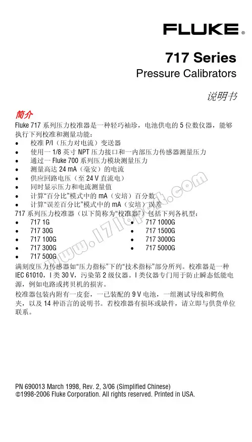
w w w.1718p or t.co m®717 SeriesPressure Calibrators说明书简介Fluke 717 系列压力校准器是一种轻巧袖珍,电池供电的 5 位数仪器,能够执行下列校准和测量功能:•校准 P/I(压力对电流)变送器•使用一 1/8 英寸 NPT 压力接口和一内部压力传感器测量压力•通过一 Fluke 700 系列压力模块测量压力•测量高达 24 mA(毫安)的电流•供应回路电压(至 24 V 直流电)•同时显示压力和电流测量值•计算“百分比”模式中的 mA(安培)百分数•计算“误差百分比”模式中的 mA(安培)误差717 系列压力校准器(以下简称为“校准器”)包括下列各机型:•717 1G •717 30G •717 100G •717 300G •717 500G •717 1000G •717 1500G •717 3000G •717 5000G满刻度压力传感器如“压力指标”下的“技术指标”部分所列。
校准器是一种IEC 61010,I 类 30 V,污染第 2 级仪器。
I 类仪器专门用于防止瞬态低能电源,例如电路或拷贝机的损害。
校准器包装内附有一皮套,一已装配的 9 V 电池,一组测试导线和鳄鱼夹,以及 14 种语言的说明书。
若校准器有损坏或缺件,请立即与供货单位联系。
PN 690013 March 1998, Rev. 2, 3/06 (Simplified Chinese)1998-2006 Fluke Corporation. All rights reserved. Printed in USA.ww w .1718p or t .co m 输入单位校准器根据下列单位测量与显示压力传感器输入端。
• psi (磅/平方英寸) • inH 2O@4 °C • inH 2O@20 °C • cmH 2O@4 °C • cmH 2O@20 °C • Bar (巴) • mbar (毫巴) • kPa (千帕) • inHg@0 °C • mmHg (毫米汞柱)• kg/cm 2(千克/平方厘米)如果装置选择不当,Fluke 700P 压力模块的输出可能会太低而无法显示, 或导致校准器显示出OL (过载)的字眼。

PN 4563700July 2014 (Simplified Chinese)© 2014 Fluke Corporation. All rights reserved. Specifications are subject to change without notice. All product names are trademarks of their respective companies. 12E+ Digital Multimeter用户手册有限保证和责任限制Fluke 保证本产品从购买日起三年内,没有材料和工艺上的缺陷。
本项保证不包括保险丝、可弃置的电池或者因意外、疏忽、误用或非正常情况下的使用或处理而损坏的产品。
经销商无权以 Fluke 的名义提供其它任何保证。
保证期间,如果有维修上的需要,请将损坏的产品(附上故障说明)送到您最近的 Fluke 授权服务中心。
本项保证是您唯一可以获得的补偿。
除此以外,Fluke 不作其它任何明示或暗示的保证,例如适用于某一特殊目的的保证。
FLUKE 不应对基于任何原因或推测的任何特别、间接、偶发或后续的损坏或损失负责。
由于某些州或国家不允许将暗示保证或偶发或后续损失排除在外或加以限制,故上述的责任限制或许对您不适用。
Fluke CorporationP.O. Box 9090 Everett, WA 98206-9090 U.S.A. Fluke Europe B.V. P.O. Box 1186 5602 BD Eindhoven The Netherlands11/99Service Centers:Fluke Beijing Service Center Room 401 SCITEC Tower Jianguomenwai Dajie Beijing 100004, PRCTel: 400-810-3435 Shanghai Shilu Instrument Co., Ltd.#139, Lane 2638, Hongmei Road (South) Shanghai 201108Standard Number: Q/SXAV 1-2002目录标题页码概述 (1)如何联系 Fluke (1)安全须知 (2)仪器概述 (5)接线端 (5)显示屏 (6)自动关机 (7)背照灯自动关闭 (7)测量 (7)手动及自动量程选择 (7)数据保持 (8)测量交流电压和直流电压 (8)测量交流或直流电流 (9)测量电阻 (10)通断性测试 (10)i12E+用户手册测试二极管 (11)测量电容 (11)维护 (12)一般维护 (12)测试保险丝 (13)更换电池和保险丝 (13)维修和零件 (14)通用技术指标 (16)准确度指标 (17)交流和直流电压 (17)交流和直流电流 (18)二极管测试、电阻和电容 (19)输入特性 (20)ii概述Fluke 12E+ Multimeter(以下称本产品)是 4000 计数仪器。
15B+/17B+/18B+Digital MultimeterSafety InformationContact FlukeFluke Corporation operates worldwide. For local contact information, go to our website: .T o register your product, or to view, print, or download the latest manual or manual supplement, go to our website: /productinfo .+1-425-446-5500 ********************Fluke Corporation P.O. Box 9090Everett WA 98206-9090U.S.A.Fluke Europe B.V.P.O. Box 11865602 BD Eindhoven The NetherlandsPN 4527616 (English)May 2014 Rev. 1, 4/24©2014-2024 Fluke Corporation. All rights reserved. Specifications are subject to change without notice. All Product names are trademarks of their respective companies.1-Year Limited Warranty.See the Users Manual for the full warranty.Safety InformationA Warning identifies hazardous conditions and procedures that are dangerous to the user. A Caution identifies conditions and procedures that can cause damage to the Product or the equipment under test.XW WarningTo prevent possible electrical shock, fire, or personal injury:●Carefully read all instructions.●Read all safety information before you use the Product.●Use the Product only as specified, or the protection supplied by the Product can becompromised.●Do not use the Product around explosive gas, vapor, or in damp or wet environments.●Examine the case before you use the Product. Look for cracks or missing plastic. Carefully lookat the insulation around the terminals.●Do not use the Product if it is damaged.●Do not use the Product if it operates incorrectly.●Comply with local and national safety codes. Use personal protective equipment (approvedrubber gloves, face protection, and flame-resistant clothes) to prevent shock and arc blast injury where hazardous live conductors are exposed.●Use only correct measurement category (CAT), voltage, and amperage rated probes, test leads,and adapters for the measurement.●Do not use test probes in CAT III environments without the protective cap installed. Theprotective cap decreases the exposed probe metal to <4mm. This decreases the possibility ofarc flash from short circuits.●Measure a known voltage first to make sure that the Product operates correctly.●Limit operation to the specified measurement category, voltage, or amperage ratings.●Do not apply more than the rated voltage, between the terminals or between each terminal andearth ground.●Do not touch voltages >30 V ac rms, 42 V ac peak, or 60 V dc.●Do not use test leads if they are damaged. Examine the test leads for damaged insulation andmeasure a known voltage.●Connect the common test lead before the live test lead and remove the live test lead before thecommon test lead.●Keep fingers behind the finger guards on the probes.●Remove all probes, test leads, and accessories before the battery door is opened.●Do not exceed the Measurement Category (CAT) rating of the lowest rated individual componentof a Product, probe, or accessory.●Remove the batteries if the Product is not used for an extended period of time, or if stored intemperatures above 50 °C. If the batteries are not removed, battery leakage can damage the Product.●Replace the batteries when the low battery indicator (P) shows to prevent incorrectmeasurements.●Use the correct terminals, function, and range for measurements.●Disconnect all test leads from any hazardous voltage before switching to the LED TEST function.Refer to the LED TEST section for proper measurement technique and interpretation of results (for 18B+ only).●Do not use the HOLD function to measure unknown potentials. When HOLD is turned on, thedisplay does not change when a different potential is measured.●Disconnect power and discharge all high-voltage capacitors before you measure resistance,continuity, capacitance, or a diode junction.●Remove circuit power before you connect the Product in the circuit when you measure current.Connect the Product in series with the circuit.●Remove the input signals before you clean the Product.●Use only specified replacement fuses.●Have an approved technician repair the Product.●Remove the test leads and any input signals before replacing the fuses.●Install ONLY replacement fuses with the specified amperage, voltage, and interrupt ratings.●Disconnect test leads before opening the case or the battery door.For safe operation and maintenance of the Product:●Repair the Product before use if the batteries leak.●Batteries contain hazardous chemicals that can cause burns or explode. If exposure to chemicalsoccurs, clean with water and get medical aid.SymbolsThe table below lists the symbols that can be used on the Product or in this document.Symbol Description Symbol Description»Consult user documentation.X WARNING. HAZARDOUS VOLTAGE. Risk ofelectric shock.W WARNING. RISK OF DANGER.M Battery¼Measurement Category II is applicable to test and measuring circuits connected directly to utilization points (socket outlets and similar points) of the low-voltage MAINS installation.½Measurement Category III is applicable to test and measuring circuits connected to the distribution part of the building’s low-voltage MAINS installation.¾Measurement Category IV is applicable to test and measuring circuits connected at the source of the building’s low-voltage MAINS installation.P Conforms to European Union directives.~This product complies with the WEEE Directive and its marking requirements. The affixed label indicates that you must not discard this electrical/electronic product in domestic household waste. Do not dispose of this product as unsorted municipal waste. For information about take-back and recycling programs available in your country, see the Fluke website.General SpecificationsMaximum voltage between any T erminaland Earth Ground..............................600 VMaximum voltage betweenV-COM T erminals...............................1000 VBattery Type........................................2 AA, IEC LR6T emperatureOperating.......................................0 °C to 40 °CStorage...........................................-30 °C to 60 °CRelative HumidityOperating Humidity....................0 % to 90 % (10 °C to 30 °C), 0 % to 75 % (30 °C to 40 °C) Operating Humidity,40 MΩ Range................................0 % to 80 % (10 °C to 30 °C), 0 % to 70 % (30 °C to 40 °C) AltitudeOperating.......................................2000 mStorage...........................................12 000 mT emperature Coefficient.................0.1 X (specified accuracy) /°C (<18 °C or >28 °C)Fuse ProtectionmA or μA inputs...........................0.44 A, 1000 V, IR 10 kAA input............................................11 A, 1000 V, IR 17 kAIP Rating...............................................IEC 60529: IP 40 Safety....................................................IEC 61010-1, IEC 61010-2-033, 600 V CAT III, 300 V CAT IV,Pollution Degree 2Electromagnetic Compatibility (EMC)International.................................IEC 61326-1: Portable Electromagnetic Environment; IEC 61326-2-2CISPR11: Group1, Class AGroup 1: Equipment has intentionally generated and/or uses conductively-coupled radio frequency energy that is necessary for the internal function of the equipment itself.Class A: Equipment is suitable for use in all establishments other than domestic and those directly connected to a low-voltage power supply network that supplies buildings used for domesticpurposes. There may be potential difficulties in ensuring electromagnetic compatibility in otherenvironments due to conducted and radiated disturbances.Caution: This equipment is not intended for use in residential environments and may not provide adequate protection to radio reception in such environments.Korea (KCC)...................................Class A Equipment (Industrial Broadcasting & Communication Equipment) Class A: Equipment meets requirements for industrial electromagnetic wave equipment and theseller or user should take notice of it. This equipment is intended for use in business environments and not to be used in homes.USA (FCC)......................................47 CFR 15 subpart B. This product is considered an exempt device perclause15.103.。
编号:
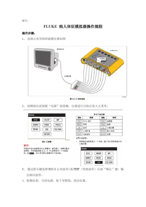
FLUKE 病人体征模拟器操作规程
操作步骤:
1、连接心电导线和被测仪器如图
2、按模拟仪前面板“电源”按钮键,仪器进行自检后进入主菜单;
3、通过箭头键选择ECG(X心电波形)或PERF(性能波形)后按“确认”键,输
出相应波形。
4、检测结束,关闭电源,取下导联线,清洁仪器。
注意事项:
1、使用前先检查外壳,阅读安全须知;
2、当显示电池电量不足时请更换电池,以防测量不正确。
维护保养:
1、每周清洁仪器表面的灰尘。
2、每周检查一次测试仪器外壳接地线、测试端连线连接是否破损、松动。
编制:审核:批准:
日期:日期:日期:。
fluke万用表运用阐明书中FLUKE15B型和FLUKE17B可以丈量电压、电阻、电流、二极管、三极管、MOS场效应管的丈量等几大功用归纳在一同的健旺的一款小仪器。
为了让你十分好的把握万用表丈量办法,电工之家来详解一下它的运用办法和功用与留心事项。
一、丈量电压时丈量直流电压时,如电池、随身听电源等。
首要将黑表笔插进相印的孔,把旋钮选到相印方位。
二、丈量沟通电压的时表笔插孔与直流电压的丈量相同,不过应当将旋钮打到沟通档场合需的量程即可。
沟通电压无正负之分,丈量办法跟前面相同。
不论测沟通仍是直流电压,要留心本身安全,不要随意用手触摸表笔的金属有些。
三、丈量电流时丈量直流电流时。
将黑表笔刺进对应孔。
将FLUKE15B型和FLUKE17B万用表串进电路中,坚持安稳,即可读数。
四、丈量电阻时用表笔接在电阻两头金属部位,丈量中可以用手触摸电阻,但不要把手一同触摸电阻两头,这么会影响丈量精确度,因为人体是电阻很大。
五、丈量二极管时表笔方位与电压丈量相同;用红表笔接二极管的正极,黑表笔接负极,这时会闪现二极管OL。
再次对调表笔会闪现一个数值。
再次沟通表笔,闪现屏闪现OL.则为正常。
因为二极管的反向电阻很大,不然此管已被击穿或功用现已改动。
六、三极管的丈量表笔插位同上;其原理同二极管。
先假定A脚为基极,用黑表笔与该脚相接,红表笔与别的两脚别离触摸别的两脚;然后再用红笔接A脚,黑笔触摸别的两脚,且此管为PNP管。
那么集电极和发射极怎样差异呢?数字表不能像指针表那样运用指针摆幅来差异。
七、MOS场效应管的丈量运用FLUKE15B型和FLUKE17B的二极管档。
若某脚与别的两脚间的正反压降均大于2V,即闪现1,此脚即为栅极G。
再沟通表笔丈量别的两脚,压降小的那次中,黑表笔接的是D极(漏极),红表笔接的是S极(源极)。
在运用FLUKE15B型和FLUKE17B的一同也要留心以下疑问防止或许遭到电击或人员危害,以及防止对电表或待测设备构成危害,请遵循下面的常规阐明运用电表:①进行联接时,先联接公共查验导线,再联接带电的查验导线;堵截联接时,则先断开带电的查验导线,再断开公共查验导线。
IC-718使用说明书北京和瑞信通科技有限公司一、 面板介绍1、电源开关[PWR]按住1秒钟开机或关机。
2、话筒插座[MIC]连接MIC用。
3、耳机插孔[PHONES]连接耳机用。
4、音量控制钮[AF]调整输出音量。
5、射频增益/静噪控制钮[RF/SQL]调整静噪阀值电平。
6、接收频率微调钮[RIT]在屏幕显示不变的情况下,将接收频率微调±1.2KHz(启动该功能时,屏幕上出现“RIT”字样)。
7、中频频移旋钮[SHIFT]改变中频频率,SSB/CW/RTTY narrow时,±250Hz AM1.2KHzCW-narrow/RTTY narrow时,±250Hz AM时无效。
8、键盘锁定开关[LOCK]锁定键盘(锁定时屏幕出现“LOCK”字样)。
9、主旋钮选择菜单项以及调节频率或信道。
10、前置放大开关[P.AMP]将接收信号放大10db(启动该功能时,屏幕显示“P.AMP”字样)。
11、频道开关[CH]激活和关闭信道选择状态。
(处于激活状态时,屏幕上有“MEMO”字闪烁)12、存储信道号增/减按钮[DN/UP]选择存储信道,在菜单设定时,用来选择要改变的菜单项。
13、衰减开关[ATT]将接收信号衰减20db(启动该功能时,屏幕上出现“ATT”字样)。
14、天线调谐按钮[TUNER]在配AH-3,AT-120等自动天调时调谐用。
(调谐功能启动时有效)15、设置菜单键[SET]进入菜单设置状态。
16、语音压缩开启和关闭语音压缩功能,启动该功能时,屏幕上出现“COM”字样。
17、键盘输入频率,或启用第二功能等。
18、噪声抑制按钮[NB]启动或取消噪声抑制功能(启动时,屏幕上有[NB]字样出现)。
19、步进开关[TS]调整频率时最小进位值。
20、滤波器开关[FIL]选择事先在菜单中设定的中频滤波器。
21、工作模式[MODE]选择收发工作模式(注意USB转为LSB为长按此键即可转换过去)。
万用表使用说明一概述万用表具有多种功能,可测量电压、电流、电阻、电容、频率等物理量,同时可检测二极管和电路通断性,是设备安装,调试,维护的必备工具。
右图为美国Fluke(福禄克)公司生产的F117C型万用表。
Fluke117C型是由电池供电的、具有 6000个字显示屏和模拟指针显示的真有效值万用表。
仪表符合第 III 类(CAT III)IEC 61010-1第二版标准的要求。
IEC 61010-1 第二版安全标准是根据瞬态脉冲的危险性定义四种过电压图1-1类别(CAT I至 IV)。
CAT III 仪表的设计能使仪表承受配电级固定安装设备的瞬态高压。
下面以该型号为例,介绍万用表的使用方法和一些应该注意的问题。
二按键说明1显示屏符号表 1序列符号含义①Volt Alert 仪表处于Volt Alert TM非接触电压检测模式把仪表设置到通断性测试功能②把仪表设置到二极管测试功能③④输入为负值⑤危险电压。
测得的输入电压≥ 30 V 或电压过载(OL)⑥HOLD 显示保持(Display hold )功能已启用。
显示屏冻结当前读数。
⑦MINMAXMAX MIN AVG 最小最大平均(MIN MAX AVG )功能已启用。
显示最大、最小、平均或当前读数⑧(红色LED)通过非接触Volt Alert 传感器检测是否存在电压⑨LoZ 仪表在低输入阻抗条件下测量电压或电容。
⑩nµF mVµAMkΩ kHz测量单位。
⑾DC AC 直流或交流电⑿电池电量不足告警。
⒀610000 mV 指示仪表的量程选择。
⒁(模拟指针显示)模拟显示。
⒂Auto Volts (自动电压)Auto(自动)Manual(手动)仪表处于自动电压(Auto Volts)功能。
自动量程。
仪表能自动选择可获得最高分辨率的量程。
手动量程。
用户自行设置量程。
⒃+ 模拟指针显示极性⒄0L 输入值太大,超出所选量程。
⒅LEAd 测试导线警示。