功率计操作说明
- 格式:pdf
- 大小:6.81 MB
- 文档页数:94
HYP PM6803A功率计使用说明书(Ver1.0 2011‐3‐5)HYP PM6803A功率计是一款多功能,高分辨率的单相功率计。
1.0主要功能:●最大量程:650V , 3A , 999.999W。
●能同时测量、显示8项参数:电压(VRMS), 电流(IRMS), 电压峰值(Vpeak, Ipeak), 有功功率(P),视在功率(S) , 功率因数(PF), 频率(F)。
●高分辨率:电压、电流最高5位分辨率,功率测量最小分辨率0.001W。
●测量电压峰值、电流峰值,捕捉记录最大值;●采用大液晶屏显示,界面直观,操作简单易用。
可切换大/小字体显示测量结果;可控制运行(RUN)/暂停(STOP),锁定显示测量结果,方便阅读分析;可以设定捕捉记录最高的电压峰值、电流峰值,方便了解负载开机的峰值电流、长期工作时的瞬间最大峰值电流等。
●智能测试功能。
8项参数都可以进行上下限规格判断,可以开启/关闭各项参数的比对功能;有4种测试方式供选择,能自动判断待测负载接入自动启动测试,灵活地适应更多的场合使用;启动测试可以由按键、或I/O外部触发;测试结果有不同的声音、指示灯提示;可以储存15个测试文件,每个文件可以编辑名称,便于记忆。
●RS232通信。
可与HYP其他智能设备进行组合,实现更强大的测试功能;可用PC软件进行记录测量结果,或者用于二次开发。
2.0各项测量参数的技术指标:参数 输入范围或最大量程 分辨率 精确度电压真有效值 (VRMS)RMS 420.00V ,PEAK 650.00V0.01V ±0.2%F.S.电流真有效值 (IRMS)RMS 3.0000A ,PEAK 6.5000A0.0001A ±0.2%F.S.电压峰值(VPEAK) 650.00V 0.01V @1KHZ ±5%F.S.电流峰值(IPEAK) 6.5000A 0.0001A @1KHZ ±5%F.S.有功功率 (ATP) 999.999W 0.001W ±0.2%F.S.视在功率 (SUI) 999.999W 0.001W ±0.2%F.S.功率因数 (PF) 1.000 0.001 ±0.2%F.S.频率 (Fq) 15.00Hz~650.0Hz <100Hz 0.01Hz>100Hz 0.1Hz±4读数输入AC频率范围: 15.00Hz~650.0Hz采集的参数更新速率:0.5秒/次。

E4418B功率计和E4412A型功率传感器使用手册安捷仑技术公司E4418B功率计使用手册目录第一章:准备工作第二章:功率计操作第三章:参考菜单第四章:错误信息第五章:规格第一章:准备工作第一节:打开功率计1.接上电源线,打开功率计开关,此时功率指示灯亮(绿色),功率计将自检,如果自检不成功,错误指示灯将亮,请与安捷仑技术公司售后服务部联系。
注意:输入电压的范围应在交流85伏到264伏之间。
在极低的环境温度下,本仪器需要预热几分钟。
2.按照面板屏幕的显示按软键调整对比度,如果软键未出现,重复按预置键(Prev)直到出现。
3.接上功率传感器。
4.在精确测量前应保证至少预热30分钟。
测量前信号要调零、校正传感器。
第二节:前面板各键的功能1.预置键。
Preset/local2.显示键。
在前面板的左边从上数第二和第三个键。
▲▼表示在上下窗口之间选择,另一个表示是否分两个窗口显示。
3.电源开/关键。
在前面板的左下角。
4.系统/输入键和软键菜单。
System/inputs5.保存/重置键。
Save/Recall6.专用“窗口”键和软键菜单Meas/Setup,Rel/Offset,dBm/W 7.专用“频道”键和软键菜单Frequency/Cal Fac,Zero/Cal。
8.频道输入插座CHANNEL9.功率参考输出插座POWER REF10.上下左右箭头键11.与菜单相关的键Prev和More键12.软键指显示屏右边4个未标字的键,它们是选择键。
第三节:显示形式分两个窗口显示时,上面是数字式显示,下面是逻辑式显示。
1.窗口顶端菜单条。
显示“LCL”自身状态。
“ERR”错误信息。
2.单或双窗口显示区。
3.测量结果区。
4.测量单位显示区。
5.逻辑式显示区。
6.当前显示菜单的页数选择区。
7.任何软键显示区。
8.菜单目录显示区。
9.测量结果超出限制显示区。
10.相关模式打开后的显示区。
11.偏置设定后的显示区。
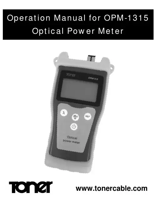
Table of Contents1. Introduction ..................................................................... 1,21.1 Summary (1)1.2 Product Features (2)1.3 Technical Parameters (2)1.4 Main Applications (2)2. Operation Instructions (3)2.1 Powering On / Off (3)2.2 Auto-Off Function (3)2.3 Backlight Operation (3)2.4 Control Panel Description ............................. 3, 43. Instructions for OPM1315 Power Meter (4)3.1 LCD Display ..................................................... 4,53.2 Wavelength Selection (5)3.3 Absolute Power Measurement ...................... 5, 63.4 Relative Power Measurement ........................ 6, 74. Maintenance (7)4.1 How to clean probe (8)4.2 9V Battery Replacement (8)5. Calibration and Measurement ...................................... 8, 95.1 Calibration for accurate performance (8)5.2 Calibration Wavelength (8)5.3 Calibration Instructions (9)6. Troubleshooting (10)7. Warranty Information (11)7.1 General Information (11)1. INTRODUCTIONThis is the operation manual for the OPM1315 Optical Power Meter.Image 1 below shows the location and function of the OPM13151.1 SUMMARYThe OPM1315 is a newly developed portable optical power meter. It is equipped with a 1.0 mm large area detector so that stability and reliability can be enhanced effectively. This unit is designed to fit the hand comfortably, and can be used for installation, debugging, and maintenance of any fiber network but is particularly suited for a singlemode network. It is light weight, has a backlight display, as well as an automatic shutdown feature. The OPM can be widely used in a variety of fields such as cable construction and maintenance, optical fiber transmission, optical fibercommunication, fiber optical sensor, and CATV. It is ideally paired with the OLS1315 Optical Light Source for network or passive testing.DC In Support Hanging Hole Optical Interface Sheath Body1.2 PRODUCT FEATURESThe OPM1315 has six optical wavelengths to choose from for testing many different systems. The OPM1315 uses a standard 9V battery which will normally yield approximately 200 hours of continuous operation. An optional AC power supply can be used for continuous operation. The OPM1315 is supplied with a SC optical adapter and there are FC and ST available as options. TheOPM1315 has auto-off function and backlight switch which can be set from the front panel.1.3 TECHNICAL PARAMETERS1.4 MAIN APPLICATIONS• Measurement of the power of an optical transmitter (dBm and W) • Testing loss of a optical fiber link• Testing insertion loss of optical passive device• Installation and maintenance of fiber optic systems2. OPERATION INSTRUCTIONS2.1 TURNING OPM1315 ON AND OFFPress the button to turn unit on.(NOTE: When the meter is switched on, the auto-off function is automatically activated.)Press the button and hold for 2 or 3 seconds to turn the meter off.2.2 AUTO-OFF FUNCTIONWhen the meter is turned on, the auto-off function is activated. If the meter is not used for 15 minutes, it will automatically shut off. To disable the auto-off function, simply push the a second time after the meter is turned on. Pushing the again will turn the auto-off function back on.2.3 BACKLIGHT OPERATIONThe backlight will automatically turn off when the meter is not used for about 1 minute to conserve battery, pressing any button will turn the light back on.2.4 CONTROL PANEL DESCRIPTIONPower ButtonUsed to turn meter on and off.Auto-off function operates through the use ofthis button.Wavelength ButtonThis button is used to select the wavelength.850nm, 1300nm, 1310nm, 1490nm,1150nm, and 1625nm. Press the buttonrepeatedly to step through the wavelengths.Measurement Selection ButtonThis button is used to select either dBm or mW, nW between the absolute and relative measurements of optical power. (mW is milliwatt, or 10 ˉ3, nW is nanowatt or 10 ˉ9 watt)Calibration ButtonPress this button to save the current power value (zero the test setup). This value can be used as a reference and will be displayed in the upper right hand corner of the LCD screen. Pressing this button quickly will switch the function to a relative power measurement. With the reference power value showing, the relative value will now be displayed between the current measurement and the reference power.The meter is now dB.3. INSTRUCTIONS FOR OPM1315 POWER METER3.1 LCD DISPLAYOnce the power is turned on the following information will display on the LCD screen:(1) When the meter is on battery power, a battery level indicator will be displayed in the lower left hand corner. When the indicator goes down to one bar, it is time to replace the battery.(2) When operating on the AC adapter, a plug symbol will be displayed above the battery indicator.(3) In the lower left hand corner of the LCD screen next to the battery indicator is the auto-off indicator. When the meter is turned on this is automatically activated and will turn the meter off after 15 minutes if the meter is not used.(4) The middle of the screen is where the optical power level is displayed, either in dBm or mw.(5) In upper right hand corner, the reference power value will be displayed when the meter is dBm. This is used when “zeroing” the power meter with a light source.(6) In the upper left hand corner, the optical wavelength selected will be shown in nm (nanometers).3.2 WAVELENGTH SELECTIONThere are a wide range of wavelengths including 850nm, 1300nm, 1310nm, 1490nm, 1550 nm for your convenience. These are available by pressing the λ button.3.3 ABSOLUTE POWER MEASUREMENT (dBm)(1) Use one fiber optic jumpers to connect the output port of the light source with the detecting port of the fiber power meter as shown in the following figure:(2) Turn on the light source and then select the wavelength to be tested.(3) Turn on the fiber power meter and select the specified wavelength.(4) The LCD display now shows the actual output power of the light source as shown in the following figure (power shown is 09.73 dBm).3.4 RELATIVE POWER (LOSS) MEASUREMENT nW (nanowatt) The nW mode is mainly used for the measurement of relative power or insertion loss. Under nW mode, the power value measured is reduced by the reference value. The insertion loss or the loss of optical fiber link will be shown on the LCD screen. Note: It is necessary to set up the reference value for each wavelength (zero the meter).(1) Use two fiber optic jumpers and a mating sleeve to connect the output port of the light source, and with the detecting port of the(2) Turn the light source on and select the wavelength to be tested.(3) Turn on the fiber power meter and select the wavelength being tested.(4) When the power meter displays the level received from the light source, press REF button and the power value will be saved as the current reference value (the display is zeroed and the actual level in dBm is displayed in the upper right of the LCD display.) this is the actual loss of the two jumpers and the mating sleeve. See figure below where the meter is zeroed and the REF shows -09.12.(5) Now disconnect the two fiber jumpers from the mating sleeve and connect to the network or device that is to be tested. The reading on the LCD screen shows the insertion loss of the network or device being tested.4. MAINTENANCEAs a highly sensitive electric & optical instrument, this meter must be maintained carefully in order to preserve its high precision and flexibility. Please pay close attention to the following items:• Before each use clean the optical fiber connector• Keep away from dust• Only keep the meter in a dry clean place away from direct sunlight • Temperature variations should be avoided to maintain accuracy • The meter cannot tolerate any kind of impact or vibration4.1 HOW TO CLEAN PROBEClean the probe of the optical power meter regularly.(1) Open the dust proof cap.(2) Screw off the adapter.(3) Use 2.5mm cotton swab with some anhydrous alcohol to lightly clean the surface of the probe.WARNING: Do not use anything hard or abrasive when cleaning the surface of the probe. Do not drop since it may crack the probe and cause the meter to not work.ATTENTION: Remember to cover the dust-cap when not using the meter.4.2 9V BATTERY REPLACEMENTOpen the back cover in order to remove and install the battery. Following is some useful information for better operation:(1) Install a new Alkaline 9V battery when the icon is displayed on the LCD screen.(2) Check the condition of the battery if the unit has been out of use for some time.5. CALIBRATION AND MEASUREMENT5.1 Accurate performance can only be achieved through the proper care and use of this meter. In order to ensure performance it is recommended that the calibration be checked annually, and if necessary recalibrate the meter.5.2 To perform a calibration of the optical power meter a light source with a known output level is required. The light source must be on the wavelength the meter will be calibrated to!5.3 To calibrate the light source follow the following instructions:(A) Open the back cover where the battery is located and you will see two toggle switches. To put the meter in calibration mode, turn either one of the toggle switches to the ON position. You are now ready to calibrate the meter.(B) Connect the meter to a known light source and set to the correct wavelength. Compare the reading on the meter to the known power level of the light source. If the readings are different then you can adjust the reading on the power meter either up or down so that it reads exactly the same as the light source. Pressing the REF button increases the display value by 0.05dB. Pressing the dBm/W button reduces the display value by 0.05dB When done, press the On/Off button to save the calibration(C) Open the back cover where the battery is located and turn the toggle switch to the OFF position for normal operation.6. TROUBLESHOOTING7. WARRANTY PERIOD7.1 GENERAL INFORMATIONThe meter has a one year free from defects warranty period. This warranty is from the date of delivery and shall be guaranteed for any defects or faults caused by material quality or non-performance. Performance under normal operating conditions is fully guaranteed. Under this guarantee the company reserves the right to carry out any maintenance it deems necessary to restore the meter to optimal performance. If maintenance fails then the unit will be replaced. One free calibration is included on any warranty item. Note: Any damage that is caused by improper use of any kind will be charged for any maintenance or necessary replacement. The company will not be responsible for any accidental damage caused by the use of this meter. WARNING: If any of the following conditions takes place, the warranty shall be null and void.(1) If the warranty label is removed.(2) Case bolts (not mentioned in the manual) have been removed.(3) Improper use of the meter.(4) If the serial number has been altered or removed.(5) If the meter has been damaged.(6) If the meter has been exposed to moisture.7.2 INCLUDED IN PACKAGEOPM1315 Portable Optical Power Meter ........................ 1 piece Operation Manual ........................................................... 1 piece 9V Battery ....................................................................... 1 piece Cotton Swab ................................................................... 1 piece OptionsAC Power Adapter model OPM-PSFC Optical Adapater model OPM-FCST Optical Adapater model OPM-STSC Optical Adapater model OPM-SC969 Horsham Road, Horsham, Pennsylvania 19044 USA800-523-5947 FAX 215-675 7543 • TEL 215 675 2053 email:*******************• 。

三和电气计器株式会社LP10激光功率计操作手册OPERATION MANUAL目录[1] 使用上的注意事项 (1)[2] 用 途 (1)[3] 特 点 (1)[4] 各部位的名称 (2)[5] 功能说明 (2)[6] 测量方法 (3)[7] 保养.管理 (5)[8] 售后服务 (5)[9] 规 格 (6)非常感谢您购买sanwa激光功率计LP10。
为了确保您正确、安全地使用此产品,请在使用前,仔细阅读此说明书。
并将此说明书与产品一起妥善保管,以便随时查阅。
[1] 使用上的注意事项●测量时,请勿直视激光,并且不要让反射光进入眼内。
激光进入眼内,有可能造成视力降低甚至失明。
尤其是红外线光源,因为肉眼无法看见,所以需要特别小心。
●若输入过强的光束,将会造成感光部的光电器件损坏,所以请勿接收超过测量范围(40 mW)的光束。
●请勿损伤、或者直接用手触摸、弄脏激光感应探头的感光面。
感光面的敏感度会因为伤痕或污垢而降低。
若感光面上有污垢,请使用酒精轻轻擦拭。
●本产品在操作结束15分钟后,会自动转换为节能状态。
在此状态下,若需再次启动时,请按MAX/MIN保持按钮恢复到测量状态,或将电源开关调至OFF 位置后再打开电源。
●使用结束后,请务必将电源开关设为“OFF”。
[2] 用 途本产品是测量激光功率用的便携式激光功率计,尺寸仅相当于上衣口袋大小。
操作性能优越、便于携带、性价比高,适用于激光仪器的检测和维修保养时的激光功率测量。
以He-Ne激光的633 nm为校正波长,可测量激光笔、DVD播放机的可视光的激光功率,直接读取功率数值。
另外测量CD机、激光打印机等校正波长以外的激光功率时,可以根据分光敏感度特性表(代表值)进行换算。
本表只能用来测量直流光(CW),无法正确地测量直流光以外的脉冲等调制光。
[3] 特 点* 尺寸仅为衣服口袋大小,便于携带。
* 激光感应探头可收纳在仪表盒内。
* 4039计数、模拟条显示。
功率计操作说明一、简介功率计是一种用于测量电力和功率的仪器。
它能够准确测量电流、电压和功率因数等参数,并可以通过显示屏或接口输出结果。
本文将详细介绍功率计的操作方法,帮助用户正确、高效地使用功率计。
二、准备工作在操作功率计之前,需要进行以下准备工作:1. 仔细阅读功率计的用户手册,了解仪器的功能和特性。
2. 确保功率计的电源连接正常,并保证电源电压稳定。
3. 准备好测试电路,确保电路正常并与功率计连接良好。
三、功率计操作步骤1. 打开功率计电源开关,并等待仪器启动。
通常会有一个启动时间,请耐心等待。
2. 设置测试参数。
使用功率计的功能按钮或旋钮,选择要测量的电流范围、电压范围和功率因数等参数。
根据具体需要,还可以设置测量精度和显示方式等。
3. 连接测试电路。
将功率计的输入端与待测电路相连,确保连接牢固、稳定。
4. 确认测量准确性。
在进行正式测量之前,可以使用已知电流、电压等参数进行校准,以确保测量结果的准确性。
5. 开始测量。
按下开始测量按钮或启动测量命令后,功率计开始采集数据并计算结果。
在测量过程中,保持待测电路的稳定,并避免其他干扰因素的影响。
6. 结束测量。
当完成所需的测量任务后,及时停止测量,并将功率计设备关闭。
四、数据处理与结果展示1. 数据处理。
功率计通常会提供数据处理功能,可以对采集的数据进行滤波、平均等处理,以提高测量结果的可靠性。
2. 结果展示。
功率计可以通过内部显示屏或连接到计算机等方式展示测量结果。
用户可以根据需要选择合适的方式进行结果展示,并进行必要的数据记录和存储。
五、注意事项1. 操作安全。
在使用功率计时,务必遵守相关的安全操作规程,确保自身和设备的安全。
2. 环境条件。
保持测试环境干净、整洁,并避免有害气体、尘埃等对测量结果的干扰。
3. 仪器保养。
定期清洁和校准功率计,以保证其测量准确性和稳定性。
4. 避免超过额定参数。
在测试时,避免超过功率计的额定电流、电压等参数,以免对仪器造成损坏或不准确的测量结果。

功率计的操作指南功率计是一种用于测量电力和功率的仪器。
它广泛应用于工业生产、能源管理、电子设备测试等领域。
正确操作功率计可以保证测量结果准确可靠,提高工作效率。
本文将为您介绍功率计的操作指南,以帮助您正确地使用功率计。
一、准备工作在使用功率计之前,首先需要进行准备工作。
这包括以下几个方面:1. 确保电源稳定:功率计通常需要接入稳定的电源供电。
在使用之前,确保电源电压稳定,电源线连接牢固。
2. 校准功率计:定期校准功率计是非常重要的,以保证测量结果的准确性。
可以参考产品说明书或者联系厂家进行校准操作。
3. 连接测试件:根据实际需求,选择适当的接口和线缆连接功率计和被测件。
确保连接牢固,信号传输正常。
二、操作步骤在准备工作完成后,可以开始进行功率计的操作。
以下是一般的操作步骤:1. 打开功率计:按下功率计的开关按钮,将其打开。
等待功率计启动完成,通常会显示出相关的信息。
2. 设置测量参数:根据实际需求,设置测量参数。
这包括功率范围、采样率、显示格式等。
可以通过功率计的菜单或者按键进行设置。
3. 进行测量:将功率计与被测件连接,并确保连接牢固。
根据需要选择所需功能,如直流功率测量、交流功率测量等。
根据实际情况,调整功率计的位置和角度,确保测量结果准确。
4. 读取测量结果:功率计会显示出测量结果,如电流、电压、功率等。
在读取测量结果时,注意观察显示是否稳定,避免因抖动或不稳定导致测量误差。
5. 记录和分析数据:根据需要,可以将测量结果记录下来,并进行数据分析。
功率计通常会提供数据存储和导出功能,以便后续使用或分析。
三、注意事项在操作功率计时,需要注意以下几点事项:1. 阅读说明书:在使用功率计之前,仔细阅读产品说明书。
了解功率计的功能、性能指标和使用方法,可以更好地进行操作。
2. 避免过载:功率计在测量高功率时,可能会出现过载的情况。
需要根据功率计的额定功率和被测件的功率确定合适的测量范围,以避免过载。

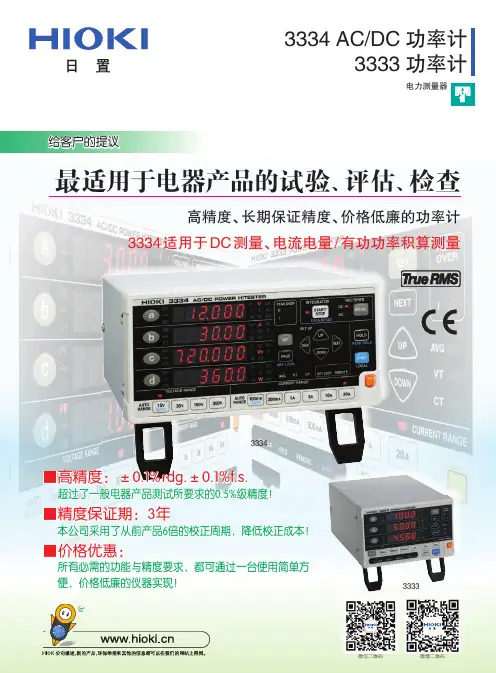
Rev.A 1.1固件说明:适用于主程序Rev.A 1.0及以上的版本AT3310数字功率计⚫AC交流/DC直流测试⚫测量参数:电压/电流/功率/频率/功率因素⚫输入电压:1.0V ~ 400V (AC) 1.0V ~ 600V (DC) ⚫输入电流:10mA ~ 20A⚫精度:±(0.4%读数+ 0.1%量程+1字)⚫U盘数据记录功能⚫上位机数据采集软件(选配)⚫RS-232C和USB通讯接口% 安柏®是常州安柏精密仪器有限公司的商标或注册商标。
安全须知当你发现有以下不正常情形发生,请立即终止操作并断开电源线。
立刻与安柏科技销售部联系维修。
否则将会引起火灾或对操作者有潜在的触电危险。
⚫仪器操作异常。
⚫操作中仪器产生反常噪音、异味、烟或闪光。
⚫操作过程中,仪器产生高温或电击。
⚫电源线、电源开关或电源插座损坏。
⚫杂质或液体流入仪器。
安全信息为避免可能的电击和人身安全,请遵循以下指南进行操作。
免责声明用户在开始使用仪器前请仔细阅读以下安全信息,对于用户由于未遵守下列条款而造成的人身安全和财产损失,安柏科技将不承担任何责任。
仪器接地为防止电击危险,请连接好电源地线。
不可在爆炸性气体环境使用仪器不可在易燃易爆气体、蒸汽或多灰尘的环境下使用仪器。
在此类环境使用任何电子设备,都是对人身安全的冒险。
不可打开仪器外壳非专业维护人员不可打开仪器外壳,以试图维修仪器。
仪器在关机后一段时间内仍存在未释放干净的电荷,这可能对人身造成电击危险。
不可在有强烈磁场或者电场的地方使用该仪器,电磁脉冲会引起仪器故障产生火灾。
在强烈磁场环境使用该仪器不要使用工作异常的仪器如果仪器工作不正常,其危险不可预知,请断开电源线,不可再使用,也不要试图自行维修。
不要超出本说明书指定的方式使用仪器超出范围,仪器所提供的保护措施将失效。
有限担保和责任范围常州安柏精密仪器有限公司(以下简称Applent)保证您购买的每一台AT3310在质量和计量上都是完全合格的。
9100p功率计说明书
1、使用者要爱护9100p功率计,确保9100p功率计的文明使用。
2、使用过程中要确保佩戴防静电手镯。
3、使用过程中不得接触9100p功率计的内芯(含连接线缆)。
4、使用过程中不允许工作台有较大的震动。
5、使用过程中不得随意切断电源,造成9100p功率计的不正常关机,不能频繁开关机。
6、使用射频线缆时不要用力过大,确保电缆保持一定的弧度、用毕线缆接头上加接头顶盖。
7、旋接接头时要旋接头的螺套,尽量确保内芯不旋转。
8、尽量协调,少用校准件,校准件用毕必须放回器件盒。
9、转接件用毕应加盖放回盒子中。
10、停用时必须关机,关闭稳压电源,方可打扫为生。
11、无源器件调试必须佩戴干净的手套。

TD-603光功率计使用说明书
TD-603光功率计的IN口代表输入口,在TD-603光功率计的接受模式下使用此口;TD-603光功率计的OUT口代表输出口,在TD-603光功率计的光源模式下使用此口。
测试发光值时直接插入,dBm显示即为发光值。
测试衰减(dB),设:发光设备出来的发光值为A,再接上需要测试的光纤线,出来的发光值为B,这两个发光值相减即为被测线路衰减。
此时可以通过自动计算来得出,在测出来设备的发光值后,按下ZERO清零(不关机情况下)后再接上需要测的光纤线,第三排将直接得出衰减。
功率计操作说明功率计操作说明1:引言本文档旨在提供详细的功率计操作说明,为用户正确使用功率计提供指导。
请阅读本文档并按照指导进行操作。
2:功率计介绍2.1 功率计的定义功率计是用于测量电力系统中电功率的仪器,能够精确测量电流、电压和功率等参数,以帮助用户评估电力系统的性能和负载情况。
2.2 功率计的组成功率计包括以下主要组成部分:- 显示屏:用于显示测量结果和参数;- 操作按钮:用于操作功率计的功能和设置;- 接口:用于连接电源、测量点等外设;- 外壳:用于保护功率计内部组件。
3:功率计的操作3.1 电源接入将功率计与电源连接,确保电源接口正确插入功率计的电源接口。
3.2 参数设置在功率计的显示屏上,使用操作按钮进入参数设置界面。
根据实际需要,设置电流、电压、功率的测量范围和单位等参数。
3.3 测量操作将待测电源或负载与功率计的接口相连,确保连接稳定可靠。
打开待测电源或负载,功率计会自动测量并显示相关参数。
3.4 数据记录与保存如果需要记录测量结果,可以使用功率计提供的数据记录功能。
按照操作说明,将测量结果保存到内部存储器或外部设备上。
3.5 故障排除在使用功率计过程中,如遇到异常情况或错误信息,请参考故障排除章节的指导,分析问题并采取相应措施。
4:附件本文档涉及的附件包括以下内容:- 功率计安装图纸- 功率计操作视频教程5:法律名词及注释- 电力系统:指由电源、输电线路、变电设备等组成的电力供应和分配系统。
- 电功率:指电流和电压的乘积,表示单位时间内的能量转移速度。
6:结束语本文档提供了详细的功率计操作说明,希望能够帮助用户正确使用功率计并准确测量相关参数。
如有任何疑问或需要进一步帮助,请联系我们的技术支持团队。
使用说明书OPERATION MANUAL CH2800系列数字功率计Digital Power MeterVer1.0常州市贝奇电子科技有限公司BEICH ELECTRONIC TECHNOLOGY CO.,LTD.注意事项:本说明书版权归常州市贝奇电子科技有限公司所有,贝奇电子保留所有权利。
未经贝奇电子书面同意,不得对本说明书的任何部分进行影印、复制或转译。
本说明书适用于CH2800系列数字功率计本说明书包含的信息可能随时修改,恕不另行通知。
最新的说明书电子文档可以从贝奇电子官方网站下载:2017年3月……………………………………..第一版公司声明本说明书所描述的可能并非仪器所有内容,贝奇电子有权对本产品的性能、功能、内部结构、外观、附件、包装物等进行改进和提高而不作另行说明!由此引起的说明书与仪器不一致的困惑,可与我公司联系。
安全警告:在使用操作和维护本仪器的任何过程中,务必遵守各项安全防护措施。
如果忽视和不遵守这些安全措施及本手册中的警告,不但会影响仪器性能,更可能导致仪器的直接损坏,并可能危及人身安全。
对于不遵守这些安全防范措施而造成的后果,贝奇电子科技有限公司不承担任何后果。
触电危险操作测试与维护仪器时谨防触电,非专业人员请勿擅自打开机箱,专业人员如需更换保险丝或进行其它维护,务必先拔去电源插头,并在有人员陪同情况下进行。
即使已拔去电源插头,电容上电荷仍可能会有危险电压,应稍过几分钟待放电后再行操作。
请勿擅自对仪器内部电路及元件进行更换和调整!输入电源请按本仪器规定的电源参数要求使用电源,不符合规格的电源输入可能损坏本仪器。
更换保险丝请使用相同规格远离爆炸性气体环境电子仪器不可以在易燃易爆气体环境中使用,或者在含有腐蚀性气体或烟尘环境中使用,避免带来危险。
其它安全事项请不要向本仪器的测试端子以及其它输入输出端子随意施加外部电压源或电流源。
输入端切勿输入交流电压。
目录使用说明书 (1)目录 (I)第一章准备使用 (3)1.1检查装运 (3)1.2检查电源 (3)1.3安装保险丝 (3)1.4连接电源线 (3)1.5环境要求 (4)1.6启动仪器 (4)第二章概述 (5)2.1产品介绍 (5)2.2测量原理 (5)2.3技术指标 (6)2.3前面板介绍 (7)2.4后面板介绍 (8)2.5显示区域介绍 (8)第三章菜单操作 (10)3.1常态页面 (10)3.1.1常态页面测试操作 (10)3.2设置页面 (11)3.2.1系统设置页面 (11)3.2.2极限设置 (12)3.2.4文件列表页面 (13)存储与调用 (13)保存文件到U盘 (14)文件列表 (15)3.2.5系统信息页面 (16)3.2.6固件升级页面 (16)第四章检定和校正 (18)1、仪器检定所需要的设备 (18)2、检定和校准的接线方法 (18)使用注意事项及故障排除方法 (18)1、仪器使用注意事项 (18)1.1建议正常测量前保持仪器通电工作30分钟。
功率计操作说明功率计是一种用于测量电路或电器消耗的功率的仪器。
它可以帮助用户准确地了解电路或电器在使用过程中的功耗情况,为节能提供重要依据。
下面将为您详细介绍功率计的操作步骤和注意事项。
1. 连接电源和信号源首先确保功率计已连接到适当的电源,并连接到待测的电路或电器上。
接通电源后,确认仪器已准备就绪。
2. 设置参数在进行功率测量之前,用户需要设定功率计的参数,包括电压范围、电流范围、功率范围等。
根据具体的测量需求灵活调整参数,确保测量结果准确可靠。
3. 进行功率测量根据已设定的参数,开始进行功率测量。
此时可以实时监测功率值的变化,同时注意仪器显示屏上的数据信息,确保测量过程中没有异常情况发生。
4. 记录数据在完成功率测量后,及时记录测量结果。
用户可以选择将数据保存在功率计内部存储器中,或通过数据接口传输到外部设备进行存档和分析。
5. 断开连接在使用完功率计后,记得断开与电路或电器的连接,关机并拔掉电源线。
定期对功率计进行清洁和维护,确保其正常运行。
注意事项:1. 在操作功率计时,务必按照操作手册的要求进行,避免操作失误导致仪器损坏或数据不准确。
2. 避免过载操作,根据电路或电器的功率范围合理设定功率计的参数,以免损坏设备。
3. 在测量高压电路时,要格外小心谨慎,避免发生安全事故。
4. 注意保护仪器免受潮湿、高温和振动等外部环境的影响,确保其长时间稳定运行。
通过以上操作说明,您可以更好地掌握功率计的正确使用方法,确保准确测量电路或电器的功率情况,为节能提供科学数据支持。
希望您能遵循以上操作步骤,正确操作功率计,确保测试结果的准确性和可靠性。
谢谢!。
智能电量测量仪RF-9901/9800 型目录目录 (1)前言 (2)开相检查 (2)安全规定 (3)第1章基本原理和功能 (4)1.1系统构造和原理框图 (4)1.2功能 (5)1.3数字、字符 (5)第2章技术指标 (6)2.1输入 (6)2.2基本误差(仪器准确度) (7)2.3显示功能 (7)2.4外观尺寸 (7)2.5常规技术指标 (8)第3章构造、按键及显示 (8)3.1前面板、后面板 (8)3.2操作键和功能显示 .........................................................9.10 3.3测量超量程/异常情况下的显示. (10)第4章操作前的准备 (11)4.1测量电路的接线 (11)4.2打开/切断电源 (11)第5章测量/显示电压、电流以有功功率、功率因数、频率 (12)5.1测量/显示电压、电流、有功功率 (12)5.2计算/显示功率因数....................................................... 12.13 5.3测量/显示频率. (13)第6章上下限判定功能 (13)6.1设定功率和电流上、下限值 (13)6.2有功功率和电流上、下限判定 (14)解释●设定上、下限值窗口A显示“AMP”表示设定电流上下限值,其中超上限指示灯亮时表示设定电流上限值,超下限指示灯亮时表示设定电流下限值,窗口C显示所要设定的电流上下限值:窗口A显示“POW”表示设定功率上下限值,其中超上限指示灯亮时表示设定功率上限值,超下限指示灯亮时表示设定功率下限值,窗口C显示所要设定的功率上下限值。
●上、下限值设定范围电流上、下限值设定范围为:0.000A~9999A。
功率上、下限值设定范围为:0.0000W~99999W。
注意●当有功功率测量值为零时,仪器不进行功率上下限判定;当电流测量值为零时,仪器不进行电流上下限判定。