CW 软件操作手册
- 格式:docx
- 大小:33.39 KB
- 文档页数:15

WhitepaperCodarSoftware version: 1.94For Windows and Linux operating system sCodar Plugin Automation for Continuous Integration ToolContentsIntroduction (3)Types of designs (3)Codar Topology Design (3)Codar Sequenced Design (4)Integration Automation (7)Sample Implementation (8)Conclusion (12)Legal notices (13)IntroductionCodar is a continuous delivery automation tool which supports deployment steps and pipeline process automation. It is always the choice for the customer to integrate the CI tool with continuous delivery tool like Codar in order to automate the process of CI-CD.Any code which is built by the build tool should be first deployed and verified on the dedicated environment before it is consumed by other lifecycle stages. This will help the team to regress the code further and finally rollout to production.The content of this whitepaper will expose the API’s which are really required to connect or integrate CI with Codar tool.Also the steps to automate the integration process are documented in this whitepaper. For any more details on the product features please refer the product guides.Types of designsThere are two types of designs which are supported by Codar which are Topology and Sequence. This section will explain the list of API which are to be used to automate the integration of CI tool with Codar’s topology design and Codar’s sequence design.Codar Topology DesignFollowing are the information which are required to automate the integrate,1.Application design idponent Id3.Application JSON to fetch the component property names which are modifiable by CI tools4.Create package API or flow5.Promote package API or flow with continuous promote yes or no optionThere are multiple ways to get the above information. One of the easiest way is to export the topology design as JSON and the id can be fetched from it. The other option is to access swagger API portal to get the list of designs which will have all the design id with JSON body. In this topology example we are going to get the information from topology JSON and for sequence design we will see how to fetch the same information through API in the section <TODO>Steps to fetch the information which are required to integration topology application design with CI tool1.Login to Codar2.Go to Designs→ Topology → Designer → Search (type the application name you want deploy through CI-CDintegration)3.Go the specific version of the application design4.On the gear box click on the Export5.This will download a generated JSON file6.Open the JSON file which is of below format and the highlighted string is the id of this design7. In order to get the component id which contains the parameters which are modifiable during deploy or re-deploy , scroll down to look for the component names which will give the detailed information about thecomponent and id.In the sample JSON the component name “PetClinic Application 4 Partial Design’ has the modifiable property which is “artifacturl”. Search for this component name and fetch the id highlighted as given below,Property which is modifiable during deploy or re-deploy which is present as part of this component. The value of this property should be set by the CI tool8.By following the above step you should have application design id, application component id and the propertywhich are required to be modified from CI tool.Codar Sequenced DesignAs mentioned in the previous section, it will require APIs to provide all the required information to automate the integration between CI tools with Codar’s sequenced design.Steps to fetch the information which are required to integration sequenced application design with CI tool1.Login to Codar2.Attach the following URI with the logged-in URL “apidocs.jsp” so the URL should be as given belowhttps://Codarmc:8444/csa/apidocs.jsp#!/Go to the section “sequence: The API for managing service design containers. (internal use only)”3.Click on the “Try it out” button on the subsection. This will list all the sequence design along with the JSON body.4.The below JSON body will contains the information about the application container id as well as the versionsunder this container. The members section will give the version id of the sequence design. In the below screen shot the id’s which are inside the box are application version design id.5.Now the next step is to fetch the component id(s) present inside application version JSON body. Thisinformation also can be fetched from the swagger API available as part of Codar.Go to the section from “https://Codarmc:8444/csa/apidocs.jsp#!/“6.Op en the API “GET /codar/app-package/{applicationDesignId}/designComponents” and provide the applicationversion design id to fetch the component information by clicking “Try it out” button7.The component id can be fetched from the response body (JSON output) which is show from the above API after“Try it out!”The highlighted id is the component id which should be used to pass any input to the property which is present as part of the component. The “displayName” is the property name which is highlighted in the second box in the below screen shotNote: Sequence based design Codar does support all properties as modifiable but re-deploy is not possible.Integration AutomationHere is the master piece which is going to integrate CI tool with Codar. Codar has got an Operation Orchestration (OO) flow which can automatically create a package and do a continuous promote release pipeline or mere deployment on first lifecycle stage.The OO flow name and the path is “Library/Integrations/Hewlett-Packard/Cloud ServiceAutomation/Components/CODAR/Devops/Continuous Deployment Flow.xml”The OO flow can be triggered remotely from a command line tool called “RSFlowInvoke.exe” with the required options. On Linux environment JRSFlowInvoke.jar can be used to trigger the workflow with the same option.RSFlowInvoke.exe and JRSFlowInvoke.jar is supported only for OO Central 9.x version but this tools still works with 10.x version.OO 10.x comes with the tool called “OOSH.bat/OOSH.sh” to accomplish the same task of invoking or trigg ering the OO flows remotely from a CIT tool. This tool may be further enhanced in the next version which can be invoked as standalone tool.This flow will take the following input in order to remotely trigger an OO flow,In the above command the option input has the following values,The password can be encrypted using the same tool and passed with an option “-ep”The SDK guide explain much more details about this tool with all the options.This flow can be invoked from any CI tool with any of the native plugin.Sample ImplementationIn this section we are going to show how a Codar plugin can be created for a CI tool using the native features of the CI tool.The sample tool taken is Bamboo. Please note that Codar already has a bamboo plugin to trigger topology based design with continuous promote yes or no option. In this sample we are going to see how a sequence design can be used in a pipeline to stand up an infrastructure, along with that install or configure the software and deploy the application remotely and how a pipeline can be kick started from Bamboo.For more details on the Bamboo CI tool please refer the Bamboo help guide.In the above or previous section we say how a flow can remotely invoked using a tool called “RSFlowInvoke.exe”.We will now see how this tool can be integrated with Bamboo and start an application release pipeline by passing appropriate inputs.Step to add an executable within Bamboo too.1.Create new executable in the Server capabilities as given in the below screen shot.2.Create a new capability3.Copy the “RSFlowInvoke.exe” tool on the Bamboo system and place it under a directory. The “Path” should havethe value as given below in the screen shot which is the actual path of the RSFlowInvoke.exe which is present on the Bamboo system.4.Create a “new build plan”5.Click on the “default job”6.Add Task to the default job7.In the above screen shot the executable selected is already configured executable for “RSFlowInvoke.exe”The arguments should be the RSFlowInvoke.exe arguments which is given below and explained in the“Integration Automation” section.8.Once it is configured trigger a test run to test the configuration by clicking the highlighted item in the boxThis is currently configured as part of the build task but this certainly can be configured as part deployment job as wellThe below is the output of the run triggered from Bamboo plugin which invokes the OO flow to start the pipeline after creating the package in the design configured.ConclusionThe instructions given in the whitepaper can be used to develop a quick and simple plugin for any CI tool to integrate with Codar in order to initiate the continuous pipeline after creating the package with required inputs. The API’s reference in this whitepaper may get enhanced and please follow the Codar guides which has references for all the APIs.Legal notices© Copyright 2008 - 2018 Micro Focus or one of its affiliates.The only warranties for products and services of Micro Focus and its affilia tes and licensors (“Micro Focus”) are set forth in the express warranty statements accompanying such products and services. Nothing herein should be construed as constituting an additional warranty. Micro Focus shall not be liable for technical or editorial errors or omissions contained herein. The information contained herein is subject to change without notice.Contains Confidential Information. Except as specifically indicated otherwise, a valid license is required for possession, use or copying. Consistent with FAR 12.211 and 12.212, Commercial Computer Software, Computer Software Documentation, and Technical Data for Commercial Items are licensed to the U.S. Government under vendor's standard commercial license.。
REFLEXW软件使用指南北京鑫衡运公司一说明本手册主要用来指导用户如何使用REFLEXW软件,它并不包括所有的细节。
如果需要了解全部细节,请参阅英文版手册。
二安装及打开软件安装软件时,只需点击setup即可。
另外,必须安装软件狗的驱动程序CbnSetup.exe,安装时也是点击即可。
打开软件时,必须将软件狗插到并口上,然后从“开始”→“程序”→“REFLEX”→ “REFLEXW”进入。
当显示出“Projectdirectory”菜单时,即可使用该软件。
(最好在桌面上建立快捷键)。
进入菜单后,建议选择菜单中的“new project”, 出现“enter name of the new project”。
输入任务名(如a1等),点击OK, 进入“Reflex_win”主菜单。
点击“Modules”, 选择各相关模块。
三输入和第一次显示GPR数据下面介绍如何输入和显示GPR数据,我们用MALA公司的RAMAC/GPR数据做例子,用其它数据时仅需改变一些选项即可。
一、输入GPR数据1.进入2D数据分析(2D-dataanalysis)2.用选项File/Open/import(文件/打开/输入)进入import(输入)菜单,此时出现REFLEXWData Import(数据输入)菜单(见右图)3.输入下列参数:input format(输入格式):RAMACoutput format(输出格式):16 bit integer(16 位整数)filename specification(指定文件名):original name(原始名,举例)选择X或Y作为剖面方向(ProfileDirection)及Y或X作为剖面常数(ProfileConstant)选择道增量(traceincrement)和/或坐标(coordinates)是否从原始数据读出(从ControlOption)4.点击选项Convert to Reflex,出现一个文件打开菜单,并在任务目录下出现子目录ASCII。

目录第一章概述3 1ROBOGUIDE简介3 2软件安装32.1ROBOGUIDE V8L安装说明32.2新建Work cell 7第二章界面介绍和基本操作15 1界面介绍15 2常用工具条功能介绍16第三章添加设备21 1周边设备的添加211.1Parts 211.2Fixtures 231.3Obstacles 251.4Workers 251.5Machines 262机器人相关设备的添加272.1机器人的添加和更改272.2机器人末端工具的添加282.3机器人DRESSOUT的添加30第四章仿真调试及视频录制32 1Roboguide中的示教盒(TP)32 2Roboguide中示教机器人35 3Roboguide仿真软件中特有的模拟程序(Simulation Program)36 4仿真视频的录制384.1功能按钮394.2Simulation Rate 394.3Display 394.4Control 404.5Collection 404.6AVI Settings 错误!未定义书签。
第一章 概述1ROBOGUIDE简介ROBOGUIDE是发那科机器人公司提供的一款仿真软件,它是围绕一个离线的三维世界进行模拟,在这个三维世界中模拟现实中的机器人和周边设备的布局,通过其中的TP(示教器)进行示教、编程,进一步来模拟它的运动轨迹。
通过这样的模拟可以验证方案的可行性同时获得准确的机器人动作节拍(运动周期时间)。
ROBOGUIDE包括搬运、弧焊、喷涂和点焊等其他子模块。
ROBOGUIDE的仿真环境界面是传统的WINDOWS界面,由菜单栏,工具栏,状态栏等组成。
使用本手册需要对机器人本体及机器人调试有一定基础。
2软件安装2.1ROBOGUIDE 安装说明打开···\Roboguide,双击文件夹下的setup.exe。
首先会弹出如下图的对话框:在安装ROBOGUIDE 前,需要先安装图中所列的组件,点击Install以安装。

C M W500常用接口按键说明-CAL-FENGHAI.-(YICAI)-Company One1CMW500常用接口按键说明前面板1、复位RESET:ctrl+r将CMW500恢复为默认设置,恢复时有两种模式可以选择,一种为Reset,另一种为Preset,这两种的默认设置略有不同,Reset常用在自动化控制时使用,Preset常在手动时使用;2 、信息INFO:ctrl+i仪表的基本信息;3、配置文件(SAVE/RCL):ctrl+s如果用户针对某一项测量任务对CMW的信号源和测量做了一些参数设置,那么用户可以通过SAVE键将这些参数设置保存为dfl配置文件,这些配置文件默认保存在D:Rohde-Schwarz/CMW/Data/SAVE目录下,用户还可以将该文件copy到其他的CMW上,通过Recall召回按键可以在其他的CMW上恢复该dfl文件的配置;4、SETUP:ctrl+e通过Setup可以对CMW500进行如下基本配置:如设置CMW500的IP地址,设置CMW500的自动化控制方式以及自动化控制地址,查看CMW500的基本信息如软硬件选件配置以及应用软件版本,对CMW500进行自检,设置参考频率和外触发方式;5、截屏Print:ctrl+p对CMW500应用程序进行截屏,保存为图片文件;6、帮助Help:F1在线的帮助文件;7、系统切换SYS:用户如果需要在Windows界面和CMW应用程序界面进行不同的操作时,SYS按键可以在CMW应用软件同windows操作系统之间进行切换;8、状态指示&开关机:通过状态指示灯,我们可以了解仪表运行的一些状态。
ERROR:仪表状态,若显示红色,则需要重启仪表或自检仪表;REMOTE:远程控制标识灯;BUSY:仪表当前测试状态;READY:仪器空闲,可以开始执行测试;9、仪器选择(DEVICE):ctrl+d该按键只对双通道配置的CMW500才起作用,通过该按键可以将仪表设置为双仪表模式,在这种模式下,两台虚拟仪表可以独立运行,同时自动化控制代码在两台虚拟仪表上的自动化控制指令相同;10、测量(MEASURE):ctrl+m加载或者选择测量的应用,一般有两种,一种是针对特定的解调测量或者接收机测量,如LTE Multi-evaluation、LTE BLER、GSM Multi-evaluation等。
Code Warrior V5.1软件使用指南一、软件安装指南二、关于BDM驱动三、创建一个新的工程四、编写与运行你的程序2011年10月16日陈万忠Code Warrior V5.1软件使用指南一、软件安装指南1. 打开文件安装文件夹2. 找到安装文件3. 双击此文件,出现安装界面:4. 点击“NEXT”按钮,出现安装路径信息。
如果修改系统默认路径,点击“change”按钮,然后修改安装路径,否则点击“NEXT”按钮。
5. 在安装过程中,根据提示信息,完成每一步的安装。
6. 安装完毕后,在所有程序中找到Code Warrior V5.1执行文件,点击执行即可进入Code Warrior V5.1集成环境。
7. 也可以拖到桌面上。
此时桌面出现如下图标:二、关于BDM驱动请将“BDM使用说明和驱动”文件夹下的文件:OpenSourceBDM.dll 和tblcf.dll以及tblcf_gdi.dll 三个文件,复制到:C:\Program Files\Freescale\CWS12v5.1\Prog\gdi目录下(或者你安装时修改过的Code Warrior V5.1所在目录\Prog\gdi子目录下),在调试时选择Open Source BDM 调试接口即可。
三、创建一个新的工程创建一个新的工程,要按照下面向导选项的8个步骤来选择完成。
双击桌面快捷图标,进入Code Warrior集成开发环境窗口。
第一步:创建一个新的工程。
第二步:选择CPU类型,选择HCS12X目录下的HCS12X Family。
第三步:选择CPU芯片型号和BDM工具TBDML。
第四步:选择编程语言,我们选择C语言编程。
第五步:添加文件到工程,一般直接按“下一步”。
第六步:快速开发应用程序选择,选None。
第七步:选择V5.0中的用户自定义模式。
第八步:选择不使用PC-Lint(TM)链接工具软件,点击“完成”按钮,Code Warrior集成开发环境就会自动生成整个工程的文件系统。
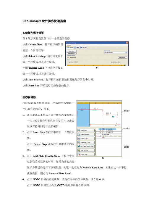
CFX Manager软件操作快速指南实验操作程序设置图1显示实验设置窗口中一个预览的程序。
点击Create New,打开程序编辑器创建一个新的程序。
点击Select Existing,通过浏览器加载一个程序或对其进行编辑。
使用Express Load下拉菜单直接加载一个程序或对其进行编辑。
点击Edit Selected,打开程序编辑器编辑所选程序的各个步骤。
点击Start Run开始运行当前加载的程序。
程序编辑器程序编辑器可用来创建一个新程序或编辑一个已存在的程序,图2。
1.在图形或文本模式下选择任何需要编辑的一步(该步骤会用蓝色高亮显示),点击温度或保持时间进行直接编辑。
2.点击Insert Step在程序中增加一个温度步骤。
点击Delete Step在程序中删除选中的步骤。
3.点击Add Plate Read to Step,在程序中指定获取荧光数据的时间。
如果当前的高亮显示步骤已经进行了读板设置,则这一选项变为Remove Plate Read。
如果在这一步不想获取数据,则点击Remove Plate Read。
4.点击GOTO步骤的重复次数,改变程序中的循环次数,图2第4步。
点击GOTO步骤数可改变GOTO循环中所包含的步骤。
1.在程序编辑控制窗口中,点击InsertGradient,图2。
2.对梯度中最低和最高温度值进行编辑,在图形模式,文本模式下或出现在文本模式右侧的梯度范围计算器中直接点击数值进行编辑,图3。
3.在梯度范围计算器中,对任何一行都可以赋予一个指定的温度。
每行的温度都会调整为合适的温度来满足指定的温度范围。
增加熔解曲线:Curve,图2。
2.在图形或文本显示模式下,点击温度值来编辑融解曲线范围的最低和最高温度,图4第5步。
3.点击增量值来编辑数据获取的温度区间。
4.点击保持时间编辑每一个增量温度的保持时间。
INMARSAT-C设备操作一. INMARSAT-C设备面板介绍Main menu bar GPS modeStatus field Title Signel meterClockFile name Character count Insert mode: Inout mode telex/ASC//Overwriting/inserting1. MAIN MENU BAR主菜单2. status field状态栏3.GPS MODE GPS 模式4.SIGNAL METER信号强度5.CLOCK时间6.TEXT FIELD电文编辑栏7.INPUT MODE输入模式8.FILE NAME文档名字9.CHARACTER COUNT字符数10.INSERT MODE插入模式二.菜单介绍1. FILE(文件⑴NEW TELEX:( 编辑新电传报文 )⑵NEW ASCII (编辑新 ASCII 报文)⑶ LOAD FILE(调出以前的报文)⑷MERGE FILE( 合并文件 )⑸ SAVE(存储文件 )⑹ PRINT TEXT(打印当前的报文)⑺ PRINT FILE(打印文件)⑻ DIRCTORY⑼ NEW PATH ⑽ EXIT⑾ ABOUT (文件目录 )(选择新的路径打开文件目录)(退出 INMARSAT-C 系统 )(关入此设备的版本,系列号,以及海上识别号)2.EDIT( 编辑文件)⑴ CUT(剪切 )⑵COPY(复制 )⑶ paste(粘贴)⑷ CLEAR(删除)⑸ DELETE WORD⑹ delete line⑺ TIME INS⑻ POSITION INS⑼ SEARCH⑽ REPLACE⑾ SET UP (删除当前单词)(删除当前行 )(插入时间 )(插入船位 )查找那一单词用某内容替代另一内容设置3.TRANSMIT ( 发射报文 )⑴ TO:选择接收报文的用户(通常在已编好的地址簿里选)⑵ LAND STATION选择陆地地面站⑶ TEXT IN EDITOR选择需发送的报文(可以是当前编的报文,也可以在已编好的文件里选)⑷ ROUTINE URGENT DISTRESS选择此次发送报文的等级(遇险,紧急,或者日常)⑸ REQUEST CONFIRMATION发送报文成功后是否需要确认⑹ PRINT发送的报文是否需要打印⑺ IMMEDIATE TRANSMISSION是立即发送还是选择随后的某一时间发送⑻ SEND SEND光标闪,回车即可发送4.LOG(日志 )⑴TRANSMIT LOG查看已发送报文的记录⑵ RECEIVE LOG⑶ EGC LOG⑷ OLD LOG FILES 查看已接收报文的记录查看已接收EGC 报文的记录查看已超过一定时间报文的记录5.DISTRESS (遇险报文的发送)⑴ LAND STATION选择发送遇险信息的地面站⑵ LATITUDE/LONGTITUDE输入遇险地点的经度和纬度⑶ COURSE/SPEED输入遇险船当时的航向及速度⑷ UPDATED以上船舶运动要素的更新时间⑸ NATURE OF DISTRESS选择遇险性质6.POSITION(人工输入船位和航向,航速信息)⑴ LATITUDE/LONGTITUDE⑵ COURSE/SPEED⑶ UPDATED⑷ STATUS输入船位经度和纬度输入本船的航向及速度以上船舶运动要素的更新时间状态7.OPTIONS(选项 )⑴SCAN INMARSAT-C 站扫描,扫描到信号最强的洋区⑵ LOG IN选择洋区入网,⑶ LOG OUT脱网,关机前需要先脱网才能关机⑷ LINK TEST链路测试⑸TRANSCEIVER STATUS 发射和接收机的状态⑹ GPS STATUS GPS 的状态⑺ TEST MODE测试模式⑻ CONFIGURATION配置①EGC设置EGC②ROUTING设置报文的路径(到存储盘或本地打印机或远程打印机)③POSITION REPORT 船位报告④NCS CHANNELS网络协调站的频道⑤DNIDS数字网络识别码⑥ENIDS EGC 网络识别码⑦PASSWORD密码⑧TERMINAL MODE终端模式8.APPLICATION ( 申请 )⑴ SAILOR C⑵ ADDRESSBOOK⑶ DIRECTORY⑷ SYSTEM查看 C 站的内容查看地址簿查看文件目录查看系统内容三. INMARSAT-C设备基本操作(注意:下面所有操作用ENTER 确认,用空格键选择,用ESC 退出)1.正确开机和关机先开显示器,打印机,后开收发机,关机顺序则反之,关机前必须先脱网。
CMW WCDMA 信令测试操作手册
1.首先复位仪表,按仪表左上角“RESET”键,如下图:
2.按软键“SIGNAL GEN”到如下界面,选择WCDMA FDD UE的Signaling测试功能模
块,如下图:
功能,这时在菜单栏会出现我们选择的三个菜单,如下图:
“UE term.Connect”设置为RMC以开始测试,注意:设置好相应的频段,更详细的设
置,如“Security”设置,请按右下角Config键,如下图:
5.这时打开手机等待手机注册到网络,注册之后可以读到手机的注册信息,如IMSI信息,
这时按“Show UE Capabilities”读取更详细手机汇报信息,如图二:
已处于连接状态,并且可以看到UE的汇报测量信息,如下图:
7.按TASK软件,选择“WCDMA Multi Eval”进入手机的发射机测试功能,按右下角的
“Config”软键,将Scenario选择为“CombinedSignalPath”,这时所有响应的上行参数都已经按照下行参数进行配置,按“Assign Views”可以选择要测量的项目,将“Multi Evaluation”键打开以进行测量,如下图,如要观察某一具体测试项,可以打开单独的测试项目,如下图:
8.按屏幕右下角“Tasks”选择BER的测量功能,打开BER测试,并获得测试结果,如
下图:
9.测试完成之后,可以选择断开连接,按Disconnect RMC即可:。
罗德与施瓦茨公司GSM信令测试CMW500操作:新手入门系列1.1 GSM和信令测试GSM是全球移动通信系统Global System for Mobile communication的简称。
GSM是第二代 (2G)移动电话系统,是数字通讯时代的开山代表作,由3GPP开发的开放标准。
信令是通讯设备之间的语言,它们按照既定的通讯协议工作,将应用信息安全、可靠、高效地传送到目的地。
这些信息在通信网络中叫做信令。
搜索其他设备、建立连接以及语音通讯,这些都是基本功能。
在这些过程中,设备之间需要大量的信令消息传递。
测试仪表可作为主设备器,模拟了这些信令交互过程,并在这些过程中,测量各项射频指标,根据测试标准门限,就可以判断该被测件是否能正常工作及其性能优劣。
我们称这种测试方法为信令测试。
所以,信令测试不但可以对被测件的射频指标进行评估,也可以判断被测件的通讯协议是否正确。
本文针对GSM信令测试,进行简要的操作介绍。
1.2 准备工作被测件,需要支持GSM;内置测试SIM卡一张;测试用射频连接线。
为了更简单的操作,可以连接一个USB接口的鼠标。
熟练掌握后,可以直接用面板上的按键进行操作。
1.3 主要按键与连接示意图打开/关闭按键请记住图中标注的四个按键。
任务栏按键RF1.4 信令连接按复位按键“RESET”,选择Global(all Instruments),点击“Preset”。
注:以下操作均可外接USB鼠标进行操作。
按SIGNAL GEN按键后,选择GSM Signaling。
选择任务栏中的GSM Signaling。
注:若没有该选项,请检查该CMW是否含有GSM信令测试选件(硬件H200A+H210A,授权KS200/KM200),以及当前仪表是否安装GSM软件。
选择GSMSignaling任务栏显示:GSM Signaling本例中,测试频带:GSM900BCCH(广播)信道号:20;承载广播消息;TCH(业务)信道号:62;手机接入后建立连接后的业务信道;下行功率DL Reference Level为-80dBm。
CWP软件的安装 一.在LINUX下建立用户CWP,在CWP下建立目录path,将源文件放 二.到path目录下,并建立bin文件夹 三.在CWP用户主目录下显示隐藏文件,修改.bash_profile 文件,在已有的export之后另起一行,分别添加 export CWPROOT=/home/CWP/path,再于 PATH=$PATH:$HOME/bin后添加 :/home/CWP/path/bin:/home/CWP 退出保存 四.从终端中分别输入 cd path … 待终端中反映完毕,分别输入 cd src make install make xtinstall make mglinstall make utils make xminstall make sfinstall 这期间可能有系统安装所等待的时间,不用急,但凡遇到yes/no,一路y下来即可。 四.为了检查是否安装完毕,在终端中输入 Suplane > data.su Suxwigb < data.su & 若出现一个简单的图像,则成功!
CWP软件的简单说明 一、文中涉及的命令全部以小写形式,均可在终端窗口下输入,以次获取自述帮助。 先说几个命令:suplane和suxwigb,more。 suplane作用是产生一个简单的零偏移距su文件,suxwigb是一个典型的X—windows绘制图形工具,如例子: suplane > data.su suxwigb < data.su more < data.su 比较全面的了解它们,请在终端中输入suplane , suxwigb ,more 。 二、关于DEMOS的应用 所有DEMOS必须把文件拷到用户根目录下,而后依照readme文件中的执行顺序,在终端中输入文件名。注意目录下的文件变动。 三、在执行DEMOS文件时,如果想清楚了解程序执行过程,请输入 more programname 由于水平有限,这里的谬误很多,希望大家能在偶尔翻看时,多多留心,发现并改正,衷心希望能和大家一起学习。谢谢 第一节 两种数据的转换 在CWP应用中免不了和两种数据打交道,su和segy格式。它们有联系也有区别。 一.数据的输入输出 1 读写编辑数据 常用命令如下: segyread---read an SEG-Y tape segywite---write an SEG-Y tape segyclean—zeor out unsigned portion(部分) of header suaddhead---put headers on bare traces and set the track and ns fields sustrip—remove the SEGYheaders from the traces supaste---paste existing(现存的) SEGY headers on existing data segyhdrs—make segyascii and innards(内部) headers for segywrite bhedtopar, setbhed---editing the binary header file surange---get max and min values for non-zero header entries suchw---change header word using one or two header word fields sugethw---get the header words in su data suedit---examine segy diskfiles and edit headers suxedit---examine segy diskfiles and edit headers 2 常规的数据转换命令 a2b—convert ascii floats to binary b2a---convert binary floats to ascii ftnstrip---convert fortran floats to c-systels floats recast---recast data type (convert from one data type to another) h2b—convert 8 bit hexadecimal floats to binary transp—transpose an n1 by n2 element matrix 二.SEGY与SU的转换 SEGY文件格式由三部分组成,镜象头文件,十进制头文件和实际的地震记录,而SU格式的文件只含有其第三部分。命令segyread可以实现两种格式的转换,使用如下: 在“big-endian”平台上, Segyread tape=/dev/rmt0 verbose=1 endian=1 >data.su 或者更常用一点的 Segyread tape=/dev/rmt0 verbose=1 endian=1 | segyclean > data.su 命令行中斜线部分是SEGY磁带的位置(或者是磁盘文件的位置),其它应用看自述文档。 三.典型命令的使用 如下命令行输入,注意主目录中文件的变化和终端中的屏幕输出。 1. suplane > data.su suxwigb < data.su & segyhdrs < data.su bhedtopar < binary outpar=binary.par setbhed bfile=binary par=binary.par [parameter1=value paramenter2=value……] segywrite b2a < data.binary n1=5 > data.ascii a2b data.binary transp < data.binary n1=5 >data.trnsp 2.Su数据简单操作 suplane >data.su sustrip < data.su head=data.headers > data.bin suaddhead data.su supaste < data.bin ns=1024 head=data.headers >data.su surange < data.su suplane | surange sugethw < data.su key=tracl,tracr.offset,dt,ns | more suplane |sugethw key=tracl,tracr,offset,dt ns output=binary > file.bin more file.bin sushw < data.su key=sx a=6400 c suplane |sushw key=sx a=6400 c=-100 j=5 | sugethw key=sx | more suplane | sushw key=offset a=200 b=200 j=5 | sugethw key=offset | more suplane | sushw key=dt,sx ,offset,a=2000,6400,200 b=0,0,200 c=0,-100,0j=0,5,5 | sugethw key=dt,sx,offset | more suedit data.su 第二节 CWP中图形打印显示工具 一.X-WINDOWS下的图形打印 1.浮点数据绘图 常用的命令有 xcontour—x contour plot of f(x1,x2) via vector plot call ximage---x imgae plot of a uniformly-sampled function f(x1,x2) xwigb---x wiggle-trace plot of f(x1,x2) via bitmap xgraph---x grapher graphs n[i] pairs of (x,y) coordinates xmovie ---image one or more frames of a uniformly sampled function f(x1,x2) 相应的,在SU平台上有以下程序 suxcontour suximage suxwigb suxgraph suxmovie suxmax 例子: suplane | suxcontour title=”contuour” & suplane | suximgae title=”image” & suplane | suxwigb title=”wigb” & suplane | suxgraph title=”graph” & suplane | suxmovie title=”movie” & suplane | suxmax tilte=”max” & suplane | junk1.su suplane | suaddnoise sn=20 >>junk1.su suplane | suaddnoise sn=15 >>junk1.su suplane | suaddnoise sn=10 >>junk1.su suplane | suaddnoise sn=5 >>junk1.su suplane | suaddnoise sn=3 >>junk1.su suplane | suaddnoise sn=2 >>junk1.su suplane | suaddnoise sn=1 >>junk1.su suxmovie < junk1.su n2=32 title=”frame=%g” loop=1 & 2.PS 下的图形打印 pscontour psimage