modelvision使用手册简化版
- 格式:doc
- 大小:1.29 MB
- 文档页数:5

光学计量有限公司MeasureMind 3DMultiSensor快速使用手册本文件由光学计量产品公司市场系统组提供。
地址:850 Hudson Ave., Rochester, New York 14621-4896 USA。
电话:585-544-0400。
传真:585-544-0131。
电子邮件:sales@或者service@。
网页: Internet: .担保书光学计量产品公司对按照本手册描述的硬件和/或软件的规格的操作提供担保,并提供从货运时间算起一年内的材料或作工的质量保证。
在此保证期内,对一切由质量问题的部件,本公司将选择给予维修,更换或提供其他有效的解决方案。
为得到这样的包修服务,客户须提供一份完整的问题说明给本公司用于检测,包括适当的文字说明(例如:结果,程序列表,样本己程序)。
若客户要求,以上提供的资料将退还给客户。
本公司不保证软件操作不中断或不出错。
本手册中提供的信息的更改将不予以通知。
本担保书不适用于以下情况出现的故障:客户提供或配置的计算机设备,操作系统或软件,未经许可的更改或误用,或在产品环境规格以外的情况下操作。
这些担保及本公司在此之下的责任,是独一无二的,并且在所有其他担保中有清楚说明或隐含说明,包括用于特殊目的的商品材和适当性的隐含担保. 在任何情况下,本公司不对任何直接的,间接的,特殊的,其他原因引起的,事故性的,或其他各种损害负任何责任。
这些损害包括利润损失,并不仅限于此,并且于与所采取行动的形式及申明的种类无关。
请注意本说明书中包括的信息基于光学计量产品公司尚未发表的经验和知识。
这些信息未得到专利权。
光学计量产品公司保留不作任何通知地更改这些信息的权利,并且不对此提供任何明确或隐含保证。
警告本设备产生,使用,并且会放射无线电波,如果不按本说明安装和使用,可能会对无线电通讯产生干扰。
在住宅区内运行此设备,可能会对广播和电视接收产生不可接受的干扰。
因此需要操作员采取必要措施来减少干扰。
easyvision 操作手册EasyVision是一个计算机视觉库,用于图像处理和计算机视觉任务。
以下是EasyVision的操作手册,包括安装、基本功能和常用功能的使用方法。
1. 安装EasyVisiona. 下载EasyVision库文件并解压缩。
b. 将EasyVision库文件添加到您的项目中。
2. 创建EasyVision对象a. 导入EasyVision库。
b. 创建一个EasyVision对象:`EasyVisioneasyVision = new EasyVision();`3. 加载图像a. 使用`easyVision.loadImage()`方法加载图像文件。
b. 可以使用绝对路径或相对路径指定图像文件的位置。
4. 图像处理a. 使用`easyVision.processImage()`方法对图像进行处理。
b. 可以使用EasyVision提供的各种图像处理函数,如灰度化、二值化、边缘检测等。
5. 计算机视觉任务a. EasyVision提供了各种计算机视觉任务的函数,如目标检测、人脸识别、图像分类等。
b. 使用相应的函数对处理后的图像进行计算机视觉任务。
6. 结果展示a. 使用`easyVision.showImage()`方法显示处理后的图像。
b. 可以使用EasyVision提供的各种图像展示函数,如绘制边界框、标记人脸等。
7. 保存结果a. 使用`easyVision.saveImage()`方法保存处理后的图像。
b. 可以将图像保存为指定格式的文件,如JPEG、PNG 等。
8. 释放资源a. 使用`easyVision.release()`方法释放EasyVision 对象占用的资源。
以上是EasyVision的基本操作手册,您可以根据您的具体需求和任务来使用EasyVision进行图像处理和计算机视觉任务。

restrictions are lifted.Trane® restaurant specialists have collaborated with leaders in restaurant facility management and members of RFMA® to develop recommendations for dark and kitchen-only HVAC system operation. The following temporary setting changes are intended to reduce energy use and cost, while running units enough to maintain proper humidity management and help prevent issues with the restaurant’s building integrity.that contract an outside company forbuilding monitoring and managementshould share this document (or otherpreferred temporary settings) for remoteimplementation.3Record all current settings! Document set points, schedules and otherimportant information. Writing downeverything will expedite start up whennormal settings can be restored.4Monitor conditions. If necessary, adjust settings to improve comfort, humidity orair quality.HVAC System Operation GuidesThe following information provides operational guidelines that will be effective in most situations. Theserecommendations can be applied to systems controlled by a programmable or smart thermostat, a local interface on a system controller or a building automation system with web or mobile phone access.If you need additional assistance, including a customized strategy for a unique situation, contact your local Trane office for additional support.Dark RestaurantsAdditional actions:Identify and shut down all gas-consumingappliances: cooking equipment, water heaters, etc. Turn equipment off and shut off gas supply valves to the appliances.Shut down all make-up air units, including condensing units and exhaust fans, at the unit disconnect on the roof.HVAC space heating and cooling equipment should remain energized, and gas supply valves should remain open.All interior and exterior lighting: adjust time-of-day schedules to unoccupied or restaurant closed levels.Turn off dish washing machines, booster heaters and other non-critical appliances in the dish area/scullery.Turn off all heat generating non-critical equipment throughout the restaurant.Walk-in coolers, freezers and ice machines:determine which can be shut down. Remove all food products, drain water and leave the doors open for ventilation.Leave the manager’s door open for ventilationif possible.* Relative Humidity Set Point if HVAC Equipment is equipped with active dehumidification—hot gas reheat.** Operate a single HVAC unit equipped with active dehumidification in a large dining area to help maintain minimum RH levels.Kitchen-Only RestaurantsAdditional actions:Identify and shut down all non-operational electric and gas consuming appliances : cooking equipment, bar equipment, displays, etc.If the hood it serves is shut down or non-operational, shut down a make-up air unit’s included condensing units and exhaust fans.In non-operational areas, adjust lighting time-of-day schedules to unoccupied levels.* Relative Humidity Set Point if HVAC Equipment is equipped with active dehumidification—hot gas reheat.** Operate a single HVAC unit equipped with active dehumidification in a large dining area to help maintain minimum RH levels.SPACETEMPERATURE SET POINTSSYSTEM CHANGE OVERAUTOFAN MODE AUTOTrane® Pivot® Smart ThermostatAdditional ConsiderationsChanging Multi-Site Enterprise Management SystemsIf equipped with an enterprise management system, change settings remotely to save time and ensure consistent, effective dark and kitchen-only conditions at multiple restaurant sites. Use the system’s functionality to implement uniform changes across multiple buildings.Adapting Settings in Single-Building Simple Thermostat SystemsIf your restaurant runs on a simple non-programmable thermostat, your ability to adjust settings may be more limited. Use this table to help guide temporary setting and operational changes.And When You Are Ready to Reopen…Trane’s restaurant HVAC professionals are ready to help. We are here to answer your questions during the shutdown and standing by to offer support when you are ready to get back up and running again. Contact us if you need new, replacement or temporary rental HVAC equipment. Your local Trane office is prepared to respond quickly when you need emergency replacements, parts or supplies.Contact your local office by visiting April 24, 2020Trane – by Trane Technologies (NYSE: TT), a global climate innovator – creates comfortable, energy efficient indoor environments through a broad portfolio of heating, ventilating and air conditioning systems and controls, services, parts and supply. For more information, please visit or .© 2020 Trane. All Rights Reserved.All trademarks referenced in this document are the trademarks of their respective owners.This is for informational purposes only. Trane believes the facts and suggestions presented here to be accurate. However, final design and application decisions are your responsibility. Trane disclaims any responsibility for actions taken on the material presented.。
机器人视觉系统用户手册欢迎使用机器人视觉系统!本手册将向您介绍机器人视觉系统的基本功能、操作指南以及注意事项,帮助您更好地了解和使用这一先进的技术。
第一部分:机器人视觉系统简介机器人视觉系统是一种利用摄像头和图像处理技术来实现对环境进行感知和识别的系统。
它可以帮助机器人在复杂的环境中进行导航、识别目标、实现自动化操作等功能,广泛应用于工业生产、医疗服务、智能家居等领域。
第二部分:系统组成和功能1. 摄像头:机器人视觉系统通常配备有高清摄像头,用于捕捉环境中的图像和视频。
2. 图像处理模块:通过图像处理算法,系统可以对捕获的图像进行分析,实现目标识别、路径规划等功能。
3. 控制单元:控制单元负责接收处理后的信息,指导机器人实现相应的操作。
4. 用户界面:系统提供了友好的用户界面,方便用户进行操作和设置。
第三部分:系统操作指南1. 系统启动:按下电源开关,等待系统启动完成,摄像头将开始工作并显示在用户界面上。
2. 环境扫描:通过摄像头进行环境扫描,系统将捕获环境的图像,并进行处理和分析。
3. 目标识别:系统可以自动识别环境中的目标物体,用户也可以手动指定目标物体进行识别。
4. 路径规划:系统可以根据目标物体的位置和环境情况,生成最优路径,并指导机器人移动。
5. 操作控制:用户可以通过用户界面对机器人进行操作控制,比如远程操控、任务设置等。
第四部分:使用注意事项1. 定期清洁:定期清洁摄像头镜片和系统外壳,以保证系统的正常工作。
2. 避免遮挡:使用过程中避免将摄像头遮挡,以免影响系统的正常功能。
3. 避免高温环境:请勿将机器人视觉系统暴露在高温环境中,以免损坏系统硬件。
4. 注意安全:使用机器人视觉系统时请注意周围环境安全,确保系统操作不会对周围人员和物体造成危险。
通过本手册的介绍,相信您已经对机器人视觉系统有了初步的了解,希望本手册可以帮助您更好地使用和操作这一先进的技术。
如果您对任何功能或操作有疑惑,可随时咨询我们的客服人员,我们将竭诚为您服务。
ModelSim SE简明操作指南(1)ModelSim SE简明操作指南第一章介绍本指南是为ModelSim5.5f版本编写的,该版本运行于UNIX和Microsoft Windows 95/98/Me/NT/2000的操作系统环境中。
本指南覆盖了VHDL和Verilog模拟仿真,但是你在学习过程中会发现对于单纯的HDL设计工作而言,它是一个很有用的参考。
ModelSim具备强大的模拟仿真功能,在设计、编译、仿真、测试、调试开发过程中,有一整套工具供你使用,而且操作起来极其灵活,可以通过菜单、快捷键和命令行的方式进行工作。
ModelSim的窗口管理界面让用户使用起来很方面,它能很好的与操作系统环境协调工作。
ModelSim的一个很显著的特点就是它具备命令行的操作方式,类似于一个shell有很多操作指令供你使用,给人的感觉就像是工作在Unix环境下,这种命令行操作方式是基于Tcl/Tk的,其功能相当强大,这需要在以后的实际应用中慢慢体会。
ModelSim的功能侧重于编译、仿真,不能指定编译的器件,不具有编程下载能力。
不象Synplify和MAX+PLUS II可以在编译前选择器件。
而且ModelSim在时序仿真时无法编辑输入波形,不象MAX+PLUS II可以自行设置输入波形,仿真后自动产生输出波形,而是需要在源文件中就确定输入,如编写测试台程序来完成初始化、模块输入的工作,或者通过外部宏文件提供激励。
这样才可以看到仿真模块的时序波形图。
另外对于Synplify来说,也只具有编译能力,但是比MAX+PLUS II可编译的verilog的内容要多,所以常常可以现在Synplify下编译,生成编译文件再送到MAX+PLUS II中使用。
ModelSim还具有分析代码的能力,可以看出不同的代码段消耗资源的情况,从而可以对代码进行改善,以提高其效率。
第二章ModelSim的主要结构ModelSim的主窗口(Main window)包括菜单栏、工具栏、工作区和命令行操作区。

LEDVISION使用手册目录第一章简介 (1)1.1概述 (1)1.2软件运行环境 (2)第二章安装与卸载 (3)2.1软件安装 (3)2.2软件卸载 (5)第三章 LEDVISION概述 (6)3.1认识LEDVISION软件界面 (6)3.2菜单和工具条按钮 (7)3.3主工具条 (10)3.4播放页面右键菜单 (11)3.5节目编辑工具栏 (11)3.6点播列表 (12)第四章节目编辑 (13)4.1节目播放文件组成 (13)4.2节目结构 (13)4.3节目页 (14)4.4节目窗口 (15)4.5节目编辑流程 (16)第五章节目播放详细说明 (23)5.1视频播放 (23)5.2图片播放 (25)5.3动画播放 (27)5.4O FFICE文件播放 (29)5.5文本播放 (31)5.6时钟播放 (34)5.7计时播放 (37)5.8网页播放 (38)5.9表格播放 (38)5.10数据库播放 (40)5.11天气预报播放 (41)5.12外部视频播放 (44)5.13环境信息播放 (45)5.14体育比分播放 (47)5.15桌面播放 (49)第六章特殊应用播放 (50)6.1播放通知 (50)6.2P OWER P OINT播放 (50)第七章定时播放和控制 (52)7.1定时指令表 (52)第八章电源和亮度控制 (54)8.1电源控制 (54)8.2亮度调节 (55)第九章远程管理 (57)9.1实时显示屏连接 (57)9.2实时显示屏管理 (59)第十章软件设置 (61)10.1软件设置 (61)第十一章用户管理 (64)11.1用户登录 (64)11.2用户信息 (64)11.3权限 (65)第十二章常见问题解答 (66)第一章简介1.1 概述LEDVISION是一款用于LED显示屏控制和播放的专业软件。
该软件功能丰富、性能优越,兼具良好的操作界面,易学易用。
LEDVISION支持视频、音频、图像、文字、Flash、Gif等形式的媒体文件播放;支持Microsoft office的Word、Excel、PPT显示;支持时钟、计时、天气预报显示;支持外部视频信号(TV、AV、S-Video、复合视频)播放;支持多页面多分区节目编辑;软件提供了丰富灵活的视频切换功能、分区特效,以及三维特效动画,让显示屏的显示效果得到完美展现。
Modelsim使用1 前言作为一种简单易用,功能强大的逻辑仿真工具,Modelsim具有广泛的应用。
这里对ModelSim作一个入门性的简单介绍。
首先介绍ModelSim的代码仿真,然后介绍门级仿真和时序验证。
2 代码仿真在完成一个设计的代码编写工作之后,可以直接对代码进行仿真,检测源代码是否符合功能要求。
这时,仿真的对象为HDL代码,比较直观,速度比较快,可以进行与软件相类似的多种手段的调试(如单步执行等)。
在设计的最初阶段发现问题,可以节省大量的精力。
2.1 代码仿真需要的文件1.设计HDL源代码:可以使VHDL语言或Verilog语言。
2.测试激励代码:根据设计要求输入/输出的激励程序,由于不需要进行综合,书写具有很大的灵活性。
3.仿真模型/库:根据设计内调用的器件供应商提供的模块而定,如:FIFO(Altera常用的FIFO有:lpm_fifo /lpm_fifo_dc等)、DPRAM等。
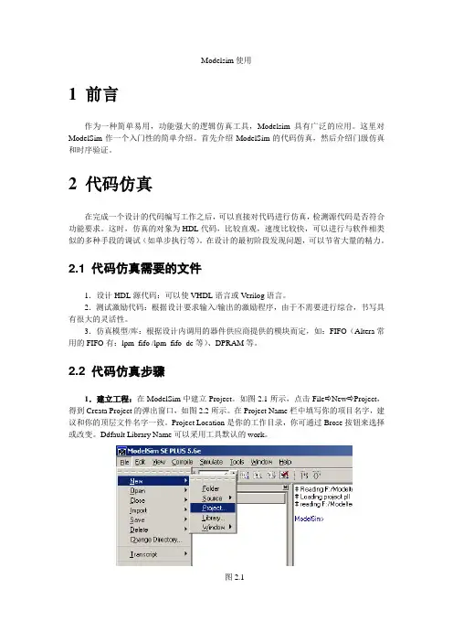
2.2 代码仿真步骤1.建立工程:在ModelSim中建立Project。
如图2.1所示,点击File⇨New⇨Project,得到Creata Project的弹出窗口,如图2.2所示。
在Project Name栏中填写你的项目名字,建议和你的顶层文件名字一致。
Project Location是你的工作目录,你可通过Brose按钮来选择或改变。
Ddfault Library Name可以采用工具默认的work。
图2.1图2.22.给工程加入文件:ModelSim会自动弹出Add Items to the project窗口,如图2.3所示。
选择Add Exsiting File后,根据相应提示将文件加到该Project中。
图2.33.编译:编译(包括源代码和库文件的编译)。
编译可点击Comlile⇨Comlile All来完成。
4.装载文件:如图2.4,点击Simulate⇨Simulate…后,如图2.5所示,选定顶层文件(激励文件),ADD加入,然后点击LOAD,装载。
VISION《LED演播室》使用说明书以及使用教程图文整理提供《新影视界许辉上海 VJ 阿辉》第一章简介 1一、概述? 1二、软件运行环境 1第二章 ?安装与卸载 3一、软件安装 3二、软件卸载 5第三章 LEDVISION概述 7一、认识LEDVISION软件界面 7二、节目结构 8三、菜单和工具条按钮 10第四章节目编辑流程 16一、设定LED屏幕大小 16二、新建节目页 17三、添加节目窗 18四、添加播放内容条 20第五章节目窗的详细制作 22一、图片播放 22二、视频播放 24三、文本播放? 26四、时钟与计时器显示 29五、天气预报播放 32六、外部视频播放 33七、 PowerPoint、?Word、Excel 播放 34八、 Flash、Gif 文件播放 35第六章播放通知和体育比分 36一、播放通知 36二、体育比分 ?36第七章定时播放和控制 38一、节目播放管理 38二、定时指令表 40第八章 5A-F异步内容管理 43一、参数设置 43二、向接收卡发送图片视频文件 43三、向接收卡发送节目文件 46第九章电源和亮度控制 48一、电源控制 ?48二、亮度调节 ?49第十章 LED大屏逐点校正 50一、逐点校正技术简介 50二、接收卡参数设置中启用校正 50三、校正操作 51第十一章远程操作? 60一、设置远程控制服务器 60二、客户机远程控制?LED显示屏 61第十二章软件设置 63一、自动设置 63二、其他设置 ?64第十三章用户管理? 66一、用户信息? 66二、权限 ?66第十四章常见问题解答? 67第一章简介一、概述LEDVISION是一款用于LED显示屏控制和播放的专业软件。
该软件采用了先进的软件技术,功能丰富、性能优越,兼具良好的操作界面,易学易用。
LEDVISION支持视频、音频、图像、文字、Flash、Gif等形式的媒体文件的播放;支持Word、Excel、PPT的显示;支持时钟、计时、天气预报的显示;支持外部视频信号(TV、AV、S-Video)的播放。
Smart Vision Development KitFAQsVersion 1.3June 16th, 2015I.Revision History:Table of ContentsI. Revision History: (2)II. General Questions: (4)1. What does the SVDK kit include? (4)2. Who are the SVDK partners and what value is supported by them? (4)3. Are other imager boards supported? (5)4. Are other PicoZed modules supported? (5)5. Can the imager board specification be supplied to customers to add their own imager? (5)6. Where do I get technical support? (5)7. Where do I get training? (6)8. Will my firewall cause issues with the demo? (6)9. In the log window of the Sphinx Viewer I see some packet loss indicated, is this normal? (6)10. Can I use every USB3 capable computer? (6)11. In U3V Sphinx Viewer I see Buffer OVERRUN messages in log files. What does it mean? (6)12. How do I re-program the SVDK for different demos? (6)13. Are the software drivers for the Aptina board available? (7)14. Are the evaluation designs on the SVDK time bombed protected? (7)15. Is it possible to use HALCON in combination to Silicon Software’s eVA? (7)16. Where can I get demo/trail version of HALCON? (7)17. Where can I buy Sensor to Image connectivity IP? (7)18. Where can I get evaluation/production version of HALCON? (8)19. Where can I buy HALCON? (8)20. Where can I get evaluation/production version of VisualApplets? (8)21. Where can I get VisualApplets documentation? (8)22. Where can I buy VisualApplets software? (8)III. Contact details: (9)II.General Questions:1.What does the SVDK kit include?⏹Development Board:o PicoZed (Zynq-7015) SOM moduleo Machine Vision Carrier Cardo Aptina 1.2MP camera moduleo Universal Power Adapterso Mini-USB-B to USB-A cableo Ethernet cableo Vivado Design Edition – Device Locked⏹Documentation (All accessed via ):o Quick Starto Getting Started Guideo Hardware User Guide⏹Further information available after registering with Sensor to Image:o Registration: http://www.sensor-to-image.de/index.php/products-mainmenu-33/registrationo Reference designs and easy to use demo instructions for machine vision connectivity from partner Sensor to Image : 1) GigE Vision, USB3Vision & CXP (Coaxpress) o All documentation and .exe files such as the Sphinx viewer software from Sensor to Image (GigE Vision viewer)o The carrier boards and Aptina sensor board schematic (in GERBER) fileso Standard reference design C-sources which includes routines for imager (AR0134) setup and basic controlo Tutorial from Sensor to Imageo Encrypted HDL and source files allowing modification of the reference design▪Video processor block and imager interface HDL (one module) which comes in sources▪Frame buffer, GigE Vision Core and Gigabit EMAC are delivered as encrypted HDL (time bombed evaluation IP)2.Who are the SVDK partners and what value is supported by them?Here is a list of the partners and what they provide for the kit:⏹Xilinx →Provides all programmable FPGA solutions. Zynq-7015 is used on PicoZed SOM.⏹Avnet→ Manufacturer and distributor of the kit⏹MVTec→ Provides demo version of their leading machine vision software, HALCONEmbedded, running on the SVDK with full library functionality. This software is fullyprocessor based.⏹Sensor to Image→ Provides reference designs for innovative machine vision connectivity(GigEVision, USB3Vision, CXP) implemented using their IP cores, support & registrationplatform, backend support on hardware for AVNET/XILINX/MVTEC⏹Silicon Software→ Provides innovative Embedded VisualApplets (eVA) tool as anevaluation version on SVDK for producing accelerated vision systems with a GUIprogramming flow3.Are other imager boards supported?Other imager boards are being planned but at this time only the Aptina imager AR0134 is supported.4.Are other PicoZed modules supported?Yes, PicoZed Zynq-7010 and Zynq-7020 are electrically compatible but with following limitations.⏹When Zynq-7010 PicoZed inserted into the SVDK: PMOD, CXP-In, CXP-OUT, HDMI will notwork⏹When Zynq-7020 PicoZed inserted into the SVDK: CXP-In, CXP-OUT, HDMI will not workFor available machine vision reference design it is necessary to contact ISM marketing to request support using these SOMs.5.Can the imager board specification be supplied to customers to addtheir own imager?Please contact Xilinx if there is interest in obtaining the specification.6.Where do I get technical support?The kit provides an out of the box experience for machine vision users that want to evaluate Zynq. The kit is low cost and does not come with any technical support package from Sensor to Image and the associated designs are supported by Xilinx Worldwide Technical Support (WTS). A tutorial and encrypted HDL files are available from the Sensor to Image web site (after registration) that will help customers take the reference design and adapt into their applications.Below is a quick guide on where to get general support for the Xilinx tools, hardware and questions on the reference designs:⏹Xilinx Vivado tools = Xilinx or Silica FAE and Xilinx WTS⏹Xilinx PetaLinux = Download area for PetaLinux, for customer hardware, can be found here:/PetaLinux⏹PicoZed SoM, = Avnet. Note is a portal for evaluationdocumentation with SVDK, for technical questions not covered by the documentation on this site please contact the relevant partner directly⏹GiGE Vision, USB3 Vision & CXP Reference designso Sensor to Image ticket support system▪Only for SVDK customers that have registered and access granted⏹Some general technical points are covered in this FAQ⏹MVTec HALCON support is as followso Customers need to read FAQ, Getting Started and Tutorialo Customers can contact MVTec directly via their Solutions email address at the bottom of this document7.Where do I get training?The kit is supported with getting started and tutorial documentation. No formal training is available at this time but please contact Xilinx marketing if you wish to register your interest in future events that are being planned.8.Will my firewall cause issues with the demo?Yes the firewall setting on the PC could cause an issue with the demos running. Being able to ping the hardware is not enough as ping, discovery and control channel works regardless the firewall settings, but streaming (runs on different port) is usually blocked by the firewall. The software included adds itself to firewall, but it needs administrator privileges. To test if streaming works we recommend sending a test packet.9.In the log window of the Sphinx Viewer I see some packet lossindicated, is this normal?Yes, as it is likely that the setup on the PC side (receive) is not optimal. GigEVision systems generally make use of a special filter driver that ensure maximum throughput on the PC side. Such a driver is also available from Sensor to Image as a paid item.10.Can I use every USB3 capable computer?Actual performance of USB3 is dependent on USB3 chipset, its connection to the PCIe bus and drivers. Especially USB3 addon board often have poor performance compared to onboard interfaces. So S2I cannot guarantee that the demo design runs on every PC.Official test PC for USB3 Vision certification follows as much as possible to USB-IF’s official test setup and uses a laptop with the Intel HM87 chipset, specifically a Dell Latitude 3440 together with the latest Microsoft XHCI driver.11.In U3V Sphinx Viewer I see Buffer OVERRUN messages in log files.What does it mean?The U3V reference design uses no external memory to buffer data, only a small fifo. If now PC is blocked for some reason and cannot serve the USB interface for a while, this internal fifo overruns and the image is corrupted. To signal this to the application the overrun status flag is set. This may happen on PCs with poor USB performance, see previous question. 12.How do I re-program the SVDK for different demos?The SVDK is provided pre-programmed with the GigE Vision reference design supplied by Sensor to Image. If the user needs to evaluate another IP reference design or a different partner solution then it is necessary to reprogram the SVDK with an appropriate JTAG programming cable. The instructions to do so are included in Getting Started Guide. Such a cable is not included in the kit as every effort has been made to keep the cost of the kit low. It is expected that most designers will already own such a programming cable.13.Are the software drivers for the Aptina board available?The SVDK supports two different drivers depending on the use case:⏹Bare metal implementation with AR0134 sources are provided after registration with Sensorto Image.⏹V4L2, Video for Linux Drivers for the AR0134 are also available on request from Sensor toImage as a paid for item.14.Are the evaluation designs on the SVDK time bombed protected?Yes the partner solutions have the following time out periods⏹Sensor to Image –30 mino Hardware can also support a paid design on the hardware with no time bomb)⏹Silicon Software Embedded Visual Applets –30 min⏹MVTec HALCON software –30 mino SVDK is for evaluation of HALCON only. Contact MVTec for more information on customer implementations on their hardware.15.I s it possible to use HALCON in combination to Silicon Software’seVA?eVA is designed to work in combination with HALCON, i.e. HALCON on the PS of Zynq and eVA in the PL. At this time, there isn’t a demonstration for the SVDK for this but we would encourage dialogue with Silicon Software for customer specific requests.16.Where can I get demo/trail version of HALCON?This will be hosted on Sensor to Image website.Please register here to get username and password for HALCONtrial access.http://www.sensor-to-image.de/index.php/products-mainmenu-33/registrationAccess the below link for demo/trial version:https:///There will be a folder called HALCON.17.Where can I buy Sensor to Image connectivity IP?Please follow the below link:⏹http://www.sensor-to-image.de/index.php/kontaktfomular18.Where can I get evaluation/production version of HALCON? Please contact MVTec below:⏹/halcon/support/19.Where can I buy HALCON?Please follow the below link:⏹/halcon/sales/20.Where can I get evaluation/production version of VisualApplets? Please contact Silicon Software below:⏹/en/contact.html21.Where can I get VisualApplets documentation?Please follow the below link:⏹/en/products/239-va-svdk-en.html22.Where can I buy VisualApplets software?Please follow the below link:⏹/en/sales-menu.htmlIII.Contact details:Please contact your sales representative/FAE or follow the links below: Xilinx Inc./about/contact.htmlAvnet/en-us/contact-us/Pages/default.aspx MVTec (HALCON)*******************Sensor to Imagehttp://www.sensor-to-image.de/index.php/kontaktfomularSilicon Software (Embedded Visual Applets)/en/contact.html。
广州三拓识别技术有限公司GUANGZHOU SANTUO INDETIFCATION TECH.CO.,LTD.康耐视VisionPro操作手册V1.02013522‐‐•设置IP地址•获取图像•图像定位•条码检测•结果输出(超级终端)设置IP地址1,手动配置电脑网卡的IP地址。
如下图:2,从开始菜单/Cognex菜单下打开GigE Vision Configuration Tool.VisionPro以太网相机IP地址配置软件3,配置相机的IP地址与电脑对应网卡的IP地址为同一个网段。
获取图像1,启动VisionPro主程序2,双击image Source (图像来源) 打开设置对话框。
3,选择“照相机”。
并从相机列表里选择对应的相机。
然后视频格式选择“Mono”。
注明:Mono表示黑白图像。
4,点击“初始化取相”,修改曝光时间为0.5ms.取消时限前面的勾。
说明:”时限”即取图像超时。
表示执行了取图像的命令,但在设定时间内没有获取到图像。
多在外部触发模式时,等待外部电眼等触发信号时间过长而报错。
5,点击左Image Source 窗口左上角的相机符号,即显示实时画面。
在画面上点击右键来缩放图像等。
6,若需要设置为外部电眼触发。
可切换到“闪光灯和触发器”页面。
选择“硬件自动”选项。
图像定位1,选择“作业编辑器”窗口。
点击左上角的“单次运行作业”按钮。
获取一张图像。
2,从窗口工具栏的“显示VisionPro工具”打开工具窗口。
里面为此软件的检测算法。
3,定位图像设置步骤。
首先从工具窗口拖动CogPMAlignTool和CogFixtureTool到作业编辑器。
并按住鼠标左键对这两个工具进行连线编程。
如下图。
4,双击CogPMAlignTool1,在弹出的窗口对其参数进行设置。
首先点击“抓取训练图像”按钮。
“训练图像”表示一张标准的图像。
若相机现在拍的图像不是很理想,则重新执行拍照动作后再点击此按钮。
visionpro deep learning 使用手册VisionPro深度学习使用手册欢迎使用VisionPro深度学习!本手册将为您提供详尽的使用指南,帮助您充分利用VisionPro深度学习功能。
请按照以下步骤操作,以获得最佳的使用体验。
第一步:安装和配置VisionPro深度学习在开始使用VisionPro深度学习之前,您需要先安装和配置软件。
确保您已获得最新版本,并具备以下准备工作:1. 确认您的计算机系统满足最低配置要求。
2. 安装VisionPro深度学习软件并按照安装向导进行设置。
3. 配置深度学习框架,如TensorFlow或PyTorch。
4. 准备好您的训练数据集和图像库。
第二步:创建和训练深度学习模型在VisionPro深度学习中创建和训练模型是非常重要的步骤。
请按照以下步骤进行操作:1. 打开VisionPro深度学习软件,并选择“新建模型”选项。
2. 在模型编辑器中,选择适当的模型类型,如分类、目标检测或语义分割。
3. 导入训练数据集并进行数据预处理。
4. 在模型编辑器中添加网络层、激活函数和损失函数,构建您的深度学习模型。
5. 配置训练参数,如学习率、迭代次数和批次大小。
6. 启动训练过程,并监控训练过程中的准确率和损失。
第三步:模型测试和性能评估在训练完成后,需要对模型进行测试和性能评估,确保模型的稳定性和准确性。
下面是一些建议的步骤:1. 划分测试集,并导入测试数据。
2. 使用已训练的模型进行测试,并记录测试结果。
3. 评估模型的准确率、召回率和F1-score等指标。
4. 根据评估结果,对模型进行改进或优化。
第四步:部署和应用模型在您满意模型的性能后,可以将其部署到实际应用中。
本步骤包括以下内容:1. 导出训练好的模型以备后续使用。
2. 集成深度学习模型和VisionPro视觉工具之间的连接。
3. 在实际生产环境中应用模型,并对其进行实时预测或分析。
4. 针对实际应用中的问题,对模型进行调整和优化。
model变频器使用说明康泰
model康泰变频器使用说明书:
不能让导线头或螺钉掉入驱动器中。否则引起驱动器损坏!请将
驱动器安装在震动少,避免阳光直射的地方。两个以上变频器置于同
一个柜子中时,请注意安装位置,保证散热效果。必须遵守本手册的指
导,由专业电气工程人员施工,否则会出现意想不到的危险!变频器
和电源之间必须有断路器隔开,否则可能发生火警!接线前请确认电
源处于零能量状态,否则有触电的危险!请按标准对变频器进行正确
规范接地,否则有触电危险!绝不能将输入电源连接到变频器的输出
端子(U、V、W)上。不要接错线!否则引起驱动器损坏!确保线路符合
EMC要求及所在区域的安全标准,所用导线线径请参考手册的建议,
否则可能发生事故。绝不能将制动电阻直接接于直流母线(P+)、(P-)
端子之间。否则引起火警!编码器必须使用屏蔽线,且屏蔽层必须保
证单端可靠接地!请确认输入电源的电压等级是否和变频器的额定电
压等级一致:电源输入端子(R、S、T)和输出端子(U、V、W)上的接线
位置是否正确:并注意检查与驱动器相连接的外围电路中是否有短路
现象,所连线路是否紧固,否则引起驱动器损坏!变频器的任何部分
无须进行耐压试验,出厂时产品已作过此项测试。否则引起事故!
打开软件
和其它软件一样,ModelVision以工程(project)形式来管理和组织各类数据、模型、文档等模块,我们往往会将一个工区的重磁、地质等数据放到一个程中来进行处理分析,本章将介绍如何建立你的第一个ModelVision工程。
1、在file下点击new->project,点击”project”后,弹出界面,在相应位置输入对应的内容,如工程路径、工程名、描述等。
2、设置工区磁场要素,(重力不需要)
3、随时保存你的工作成果在使用ModelVision时,要养成随时保存工程的好习惯,在保存工程的过程中,ModelVision跟咱国人的思路不一样,他通过保
存”session”方式来保存某一阶段中的所有工作内容(数据、图等),点击”file”->save保存。
数据的导入和显示
1、数据导入
数据导入主要有四种:(线(profiles、网格(Grid)、钻孔(DrillholeData)、点(Pointdata)
第一步,将磁测数据在Excel中打开(ModelVision中数据组织格式必需包括Line(线号),X(X坐标)、Y(Y坐标)和Mag(磁异常)。
这一步的关键是改写第一行(表头),是其包含Line、x、y、mag(磁异常)。
第二步,将数据保存为CSV格式。
第三步,在modelvision文件菜单下依次选improt—>profiles—>GeneralASCII。
点击”Import”即可。
点击之后,弹出导入数据设置导入线号的窗口(选择要输入的线号(Line)和要输入的道(Channels)。
点击“SelectAll”(选择全部线)按钮,点击Channels(道),点击SelectAll(选择全部道)按钮,将选择把所有列导入到ModelVision中。
点击”OK”按钮,至此CSV文件导入完毕。
2、数据显示
数据输入以后,为了解重(磁)场分布情况,就需要进行各种方式的图形来显示,ModelVision中图形可以以多种方式显示,创建各类图形的菜单都在”View”。
剖面平面图制作(stackedprofile)点击”StackedProfile”菜单,弹出界面,在图中左边窗口选择要做剖平图的数据列,当然,通常选择磁异常mag。
点
击”OK”,平剖图的轮廓就显示出来了。
网格数据产生(插值),Utility下面的GridChannelData,点击该菜单弹出界面。
按提示设置好参数,点击”OK”即形成一个叫”mag”的网格数据了。
等值线和影像图制作,等值线和影像图都是以网格数据为基础,其制作步骤基本一致,等值线制作:点击View—>Map—>contour菜单,弹出界面,将插值生成的网格mag选中。
点击”OK”即完成等值线图的绘制。
数据处理
一维数据处理(略)
ModelVision中的数据处理包括1维数据处理和2维数据处理,1维数据处理主要针对剖面,而二维数据处理则针对平面数据,通常是网格文件(grid)。
所有的数据处理菜单都在”Filters”(滤波)下,也即可以将各种处理都视为滤波。
滤波又分为褶积滤波(convolutionfilter)和傅立叶滤波(FFTfilters),前者为空间域滤波,后者为频率域滤波,由于计算方便,频率域滤波使用要多一些,在数据处理过程中,需结合实际情况选择滤波方式。
二维数据处理
二维数据处理在modlevision中都统称为网格滤波(Gridfilter),各项滤波的地球物理和地质意义和第五章中介绍的一维滤波类似。
二维滤波分为褶积滤波(空间域)和FFT滤波(频率域),目前,常用频率域的GridFilter滤波,滤波菜单见图。
1、空间域二维褶积滤波(2Dconvolutinfilters),空间域褶积滤波对应菜单项是->Gridfliters->2Dconvolutinfilters,点击该菜单项后出现界面。
二维褶积滤波界面将功能相关的滤波器集合成组,所以,进行滤波时,从”滤波组”中选择对应的”滤波器”,如本图中选择了GEOPHYS中的低通滤波。
再设置好要滤波的网格数据和滤波后的网格数据名后,点击”OK”按钮后,即完成低通滤波,其它滤波操作步骤也是如此。
2、频率域滤波(Gridfilters),频率域褶积滤波对应菜单项是->Gridfliters->Gridfilters,点击该菜单项后出现如上右图所示界面,提示你选择哪个网格文件进行滤波。
如选择磁异常网格mag,点击”OK”后弹出如下左图所示滤波参数设置界面,从该图可见ModelVision的滤波功能非常丰富,基本囊括了目前所有的滤波功能,右边三个窗口增加了滤波前后对比的预览功能,实时分析滤波不通滤波方法和参数下的滤波效果。
滤波步骤也较简单,只需点击FFT下对应的滤波器,便可以看到滤波效果,认为滤波满意后,点击”saveas”按钮,将滤波厚后的数据保存下来。
3、导数变换,点击导数变换按钮(”Deravitive (advance )”),弹出如上中图所示界面。
在这个界面下可以进行任意方向任意价次的导数变换,只需在导数方向里面选择求导方向,在导数价次里输入求导阶数即可。
本例子的参数是求取垂向一阶导的,从预览可以发现垂向一阶导数将大异常分解成了若干个小异常,起到了区分浅部磁性体的作用。
4、延拓变换,在褶积滤波中向上延拓(upwardContinuation )和向下延拓(downwardContinuation )需要单独滤波器进行,在频率域滤波中,只需在一个滤波器中即可完成。
击延拓变换按钮(”Continuation ”),弹出如上右图所示界面。
只需设置延拓高度即可,大于0为向上延拓,小于0为向下延拓。
本图设置是进行上延变换的,上延高度为200,从预览图可以发现,上延后磁异常便圆滑平缓了,突出了深部磁性体,上延高度越大,反映深度越大,但是,上延的高度和反映的深度不是严格对应,目前还未见有人做出上延高度与实际反映深度直之间的定量关系的结论。
结果输出
按弹出菜单(下图左图)选择格式存盘;
输入刚存盘的文件
在”View”。