维特wt-xk3108-b说明书
- 格式:doc
- 大小:634.50 KB
- 文档页数:13

不WT-XK3018选别控制器用户操作手册2010.03版(增加静态选别)烟台维特测控科技有限公司WT-XK3018-A选别控制器目录第一章概述------------------------------------------ (3)第二章系统配置框图----------------------------------- (3)第三章主要功能和技术指标--------------------------------- (3)第四章外形尺寸及面板布置图----------------------------------- (4)第五章接口----------------------------------- (4)§1 传感器接口-------------------------------------- (4)§2 输人/输出接口-------------------------------------- (4)§3 串行接口-------------------------------------- (5)第六章标定-------------------------------------- (5)§1 称量基本参数设置-------------------------------------- (5)§2 标定-------------------------------------- (5)§3 A/D值显示-------------------------------------- (5)第七章控制方式及辅助参数设定----------------------------------- (5)§1 控制方式设定-------------------------------------- (5)§2 辅助控制参数设定-------------------------------------- (6)第八章重量设定及配方存入和调用--------------------------------- (6)§1 重量设定-------------------------------------- (6)§2 配方存入-------------------------------------- (6)§3 配方调用-------------------------------------- (6)第九章其他操作-------------------------------------- (7)§1 置零-------------------------------------- (7)§2 去皮-------------------------------------- (7)§2-1实物去皮-------------------------------------- (7)§2-2皮重清除-------------------------------------- (7)§2-3数字去皮-------------------------------------- (7)§3 累计次数显示-------------------------------------- (7)§4 查询-------------------------------------- (7)§5 时间/日期的显示和设定----------------------------------- (7)§6 启动------------------------------------- ( 7)§7 停止-------------------------------------- (7)§8 标准RS232输出格式-------------------------------------- (8)第十章维护保养及注意事项 -------------------------------------- (8)付控制时序图---------------------------------------------------------------------- (9)第一章概述WT-XK3018-A选别控制器适用各种选别控制。

C-1C Humidity:10 to 90%RH non-condensing Battery:3.6 V lithium battery (included)Battery Life with Transmissions:2 years Shelf Life with Battery Installed:4 years in quiescent mode FCC Certified:FCC ID: M5ZVM1Dimensions:38 H x 53 W x 15 mm D (1.5 x 2.1 x 0.6")Weight:43 g (1.5 oz)also used to put the device in a quiescent mode (no transmissions and very low power consumption). This is the state the device is in when you receive it. Push and hold the service switch for 10seconds or more to enter this powered down ing the OMWT Series Windows software incoming data being received from OMWT Series Wireless Transmitters can be viewed in a real-time or historical time-base chart or numerical view.High/low alarms can also be set for each transmitter signal with either a visual or audible alarm indication on the PC. Data can also be logged to disk at a user-specified rate in a text file format that can be opened up into Microsoft Excel. The OMWT Series Windows software also includes a DDE Server that can interface the data being received from OMWT Series Wireless Transmitters to other Windows software packages.Specifications Motion Range:Not a calibrated range (transmits a value of 0 to 100%)Transmission Frequency:418 MHz Transmission Range*: Up to 180 m (600') depending on environmental conditions Transmission Rate:30 to 37 seconds Operating Temperature:-40 to 85°C (-40 to 185°F)Storage Temperature:-40 to 85°C (-40 to 185°F)Wireless Motion TransmitterߜTransmits up to 180 m (600') *ߜDigital Motion Measurement via Internal Weighted Accelerometerߜ64-Bit Unique IDߜCompact ABS EnclosureߜComplies With Part 15 of the FCC RulesߜInternal Loop AntennaThe OMWT-MOT Wireless Motion Transmitter is a battery operated digital vibration sensor with a microprocessor controlled 418 MHz FCC certified radio transmitter. This transmitter is useful in applications that need to sense when motion is present or not. The OMWT-MOT has an on board time of day clock that allows it to spend most of the time in a low power quiescent state.At predetermined time intervals the clock will wake up the onboard microprocessor. Unique serial number information and digital vibration data is combined with a CRC-16 error check and transmitted in a very short data packet that results in a transmitter on time of only 15 milliseconds. This architecture allows the OMWT-MOT to consume very low energy resulting in a battery life of up to 2 years.The electronics are coated with a conformal rubber material that provides a moisture barrier against condensation. Submersion in water is not recommended. An integral pushbutton is used to activate the service switch. The OMWT-MOT is shipped with the transmitter turned off (anytime the device is to be shipped the transmitter should be turned off or must be placed in a shielded container to prevent interference that might cause shipping problems). Start the device by momentarily pushing the service switch (you will feel the button click). When the service switch is pushed, a data transmission occurs immediately and a special mark is introduced in the ID field of the transmitted data packet to indicate which device is in service or installation. The service switch is OMWT-MOTStarts at$145Ordering Example: OMWT-MOT wireless motion transmitter, OMWT-REC232wireless receiver and OMWT-SOFT Windows software, $145 +222 + 100 = $467.OMWT-MOT, $145, shown larger than actual size. OMWT-SOFT, $100, displays real-time。
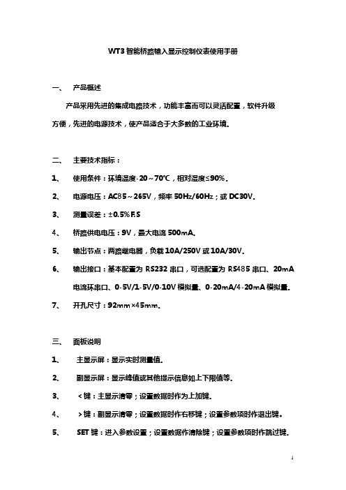
WT3智能桥路输入显示控制仪表使用手册一、产品概述产品采用先进的集成电路技术,功能丰富而可以灵活配置,软件升级方便,先进的电源技术,使产品适合于大多数的工业环境。
二、主要技术指标:1、使用条件:环境温度-20~70℃,相对湿度≤90%。
2、电源电压:AC85~265V,频率50Hz/60Hz;或DC30V。
3、测量误差:±0.5%F.S4、桥路供电电压:9V,最大电流500mA。
5、输出节点:两路继电器,负载10A/250V或10A/30V。
6、输出接口:基本配置为RS232串口,可选配置为RS485串口、20mA电流环串口、0-5V/1-5V/0-10V模拟量、0-20mA/4-20mA模拟量。
7、开孔尺寸:92mm×45mm。
三、面板说明1、主显示屏:显示实时测量值。
2、副显示屏:显示峰值或其他提示信息如上下限值等。
3、﹤键:主显示清零;设置数据时作为上加键。
4、﹥键:副显示清零;设置数据时作右移键;设置参数项时作退出键。
5、SET键:进入参数设置;设置数据作清除键;设置参数项时作跳过键。
6、ENT键:进入标定;设置数据及参数项时作为确认键。
四、进入设置SETUP1、按SET键,显示SET,确认;2、ALA1输入清零范围值,确认;3、ALA2输入上限值(超出所设定的仪表上限输出有效),确认;4、ALA3输入下限值(低于所设定的仪表下限输出有效),确认;5、ALA4输入峰峰值自动清零范围,确认;6、ALA5设置上下限判断方式及串口发送的数据,0实时值,1峰值,确认;7、ALA6设置模拟量输出方式,0-5(0-5V、0-10V或0-20mA),1-5(1-5V或4-20mA),此时有一标准5V或20mA输出供校准,确认;8、ALA7输入自动清零范围,确认;9、SC设置串口发送方式,0连续,1命令,确认;10、BAUD设置波特率,600~19200,确认;11、ADDR设置仪表地址,00~99,00无地址,确认,返回正常状态。

海南威特WT2000说明书WT-2000变电站综合自动化系统技术使用说明书(中文版)(V5.X)海南威特电气集团有限公司2003年12月目录第一章总体说明 (4)一变电站层 (4)二间隔层 (5)第二章主要技术指标 (6)一WT-2000综合自动化系统技术参数 (6)二WT-2000系列微机成套保护技术参数 (6)第三章系统配置及通讯网 (8)一系统软件 (8)二软件系统的功能 (9)三装置配置 (9)四通讯网 (11)第四章保护原理 (12)一WT-2000系列微机测控保护装置各项功能表 (12) 二保护原理 (12)1. WT-2021差动保护装置 (12)2. WT-2023变压器高压侧后备保护 (14)3. WT-2024变压器低、中压侧后备保护 (15)4. WT-2031 35kV、10kV线路保护 (17)5. WT-2032 电容器保护 (18)6. WT-2043 备用电源自投装置 (19)7. WT-2025 接地/站用变保护 (20)8. WT-2034 电动机保护 (21)第五章监控部分 (22)一测量 (22)二控制 (22)三事件顺序记录 (23)第六章装置安装调试大纲 (23)一装置的外部接线说明 (23)二绝缘及耐压检查 (23)三装置通电前的检查 (23)四装置通电检查 (23)五整机通电检查 (23)六开入、开出回路的检查 (24)七定值的设置 (24)八整组试验 (24)九其它注意事项 (25)第七章保护测控装置操作指南 (25)一保护投退 (26)二保护定值 (27)三事件记录 (27)四输入输出 (28)五采样数值 (29)六实时时钟 (29)七电能脉冲 (29)八出厂设置 (30)九设备信息 (31)第八章贮存、定货须知 (31)一贮存须知 (31)二订货须知 (31)附录一:定值表及保护投退的说明 (32)主变差动保护单元(WT-2021A-C,WT-2021B-C,WT-2021C-C) (32)110kV 三卷变压器高压侧后备保护定值(WT-2023A-C,WT-2023D-C) (33)110kV两卷变压器高压侧后备保护定值(WT-2023B-C,WT-2023E-C) (35)35kV两卷变压器高压侧后备保护定值(WT-2023C-C) (37)110kV变压器中压侧后备保护定值(WT-2024A-C) (38)110kV(35kV)变压器低压侧后备保护定值(WT-2024B-C)(40)35kV变压器低压侧定值(高压侧无断路器)(WT-2024C-C)(42)接地(站用)变压器保护定值(WT-2025-C) (44)公用测控单元(主变公用)定值(WT-2041A-C) (45)35 kV(10kV)线路保护定值(WT-2031-C) (47)35 kV(10kV)电容器保护定值(WT-2032-C) (49)3-10kV电动机保护定值(WT-2034A-C) (50)母线分段保护定值(WT-2033-C) (52)备用电源自投定值(WT-2043A-C) (53)线路测控单元定值(WT-2013-C) (54)开关量输入单元定值 (56)附录二:背板端子原理图 (56)附录三:保护逻辑框图 (64)1. WT-2021A、WT-2021B、WT-2021C主变差动保护逻辑框图(64)2. WT-2023A 110kV三圈变高压侧后备保护逻辑框图 (65)3. WT-2023B 110kV两圈变高压侧后备保护逻辑框图 (67)4. WT-2023C 35kV两圈变高压侧后备保护逻辑框图 (69)5. WT-2024A 主变中压侧后备保护逻辑框图 (71)6. WT-2024B 主变低压侧后备保护逻辑框图 (72)7. WT-2024C 主变低压侧后备保护(高压侧为负荷开关)逻辑框图(73)8. WT-2041A 公用测控单元(主变公用) (74)9. WT-2025 接地变(站用变)保护逻辑框图 (75)10. WT-2031 35kV、10kV线路保护逻辑框图 (76)11. WT-2034A 电动机保护逻辑框图 (78)12. WT-2033 分段保护及WT-2032电容器保护逻辑框图 (80)附录四:装置尺寸及安装开孔尺寸 (81)第一章总体说明WT-2000系列变电站综合自动化系统是我公司根据电力系统自动化及无人值班的要求,总结国内外变电站微机控制及保护的研究和生产的先进经验,采用当今先进的自动化技术、计算机技术、通信技术等高科技,推出的新一代变电站综合自动化系统。

J40XNLPRODUCT BROCHURECircled dimensions correspond to the line numbers on the tabulated chart inside the technical guide. Dimensions are in inches (millimeters).2Circled dimensions correspond to the line numbers on the tabulated chart inside the technical guide.Dimensions are in inches (millimeters).3The table below is a helpful guide to visualize the truck run time with different batteries in different applications. (Chart is a guide only and not a replacement for a site survey and full power study.)Heavy – High throughput, typically runs full capacity, runs either attachments or has high liftsMedium – High throughput, runs near capacity without attachments or high liftsLight – lower throughput, runs less than rated capacity without attachments or high liftsNote: Run time is from 100% to Lift-Lock Out. Charge time is from Lift-Lock Out to 100%.45CERTIFICATION: Hyster lift trucks meet the design and construction requirements of B56.1-1969, per OSHA Section 1910.178(a)(2), and also comply with the B56.1 revision in effectat time of manufacture. Certification of compliance with the applicable ANSI standards appears on the lift truck. Performance specifications are for a truck equipped as described under Standard Equipment on this Technical Guide. Performance specifications are affected by the condition of the vehicle and how it is equipped, as well as by the nature, condition of the operating area, proper service and maintenance of the vehicle. If these specifications are critical, the proposed application should be discussed with your dealer.NL = no load, RL = rated load。

EAN:4013288195067Size:150x130x45 mmPart number:***********Weight:570 gArticle number:8740 B HF Imperial 1Country of origin:CZ82079030Customs tariffnumber:Bit sockets with holding function for hexagon socket screwsThe holding function holds screws securely on the toolTake it easy tool finder with colour coding according to sizesKnurling on lower end for more grip when used manuallyChrome vanadium steel, matt chrome-platedBit socket with 3/8 inch drive and holding function for extremely convenient screwdriving with reduced risk of losing the screw when addressing the workpiece. "Take it easy" Tool Finder with colour coding according to size - for simple and rapid accessing of the required tool.Web linkhttp://products.wera.de/en/zyklop_ratchets_and_accessories_the_zyklop_ratchets_the_zyklop_ratchets_3_8_zyklop_accessories_3_8_8740_b_hf_imperial_1.htmlSet contents:8740 B HF *********** 1 x 1/8" x 107 mm *********** 1 x 5/32" x 107 mm *********** 1 x 3/16" x 107 mm *********** 1 x 7/32" x 107 mm *********** 1 x 1/4" x 107 mm *********** 1 x 5/16" x 100 mm ***********1 x 3/8" x 100 mmBit sockets with retaining function for hexagon socket screwsTake it easy tool finder systemManual and machine socketsThe clamping of the screw is achieved by a flexible locking ball.The holding function is especially helpful in confined,hard-to-reach spaces,where there is no room for a second hand to secure the screw.Take it easy tool finder system -with profile and size colour-coding for quick and easy tool selection.Colour-coded system for hexagon drive screws (L-Keys,Zyklop bit sockets),external hex drive screws and nuts (Joker wrenches,Zyklop sockets and Zyklop bit sockets with holding function),and TORX®drive screws (L-Keys,Zyklop bit sockets).The manual and machine sockets can be used both for hand and power tools use (non-impact).Users need just one socket set for all applications.Web linkhttp://products.wera.de/en/zyklop_ratchets_and_accessories_the_zyklop_ratchets_the_zyklop_ratchets_3_8_zyklop_accessories_3_8_8740_b_hf_imperial_1.html。
数显特斯拉计使用说明书一、概述数显特斯拉计是一款便携式、多功能的磁场测量仪器,配备了高灵敏度、低飘移的霍尔传感器,并应用了先进的数字信号处理技术,适用于测量永磁材料的表面磁场、机械零件的剩磁、磁选机或除铁器等。
可作为基本的磁参量测量仪器应用于磁性材料生产厂家和应用单位、机械制造企业、高校科研单位等。
二、功能特点2.1三种准确度:1级、2级、5级适用于不同的磁场测量场合。
2.2两种磁场单位:mT(毫特)、Gs(高斯),1mT=10Gs。
2.3测量范围:0-2400mT(24000Gs)。
2.4具有自动量程切换、一键清零、最大值保持功能。
2.5显示屏背光、5分钟自动关机功能。
2.6低功耗、轻便易携带。
2.7多种霍尔探头可供选择。
三、技术参数量程200mT(2000Gs)2000mT(20000Gs)分度值0.01mT(0.1G)0.1mT(1G)准确度(1级)±1.0%准确度(2级)±2.0%准确度(5级)±2.0%(0...1000mT),±5.0%(1000mT...2400mT)供电电源1节9V电池工作环境0℃~50℃,20%~85%R·H,不结露存储环境-20℃~70℃,<85%R·H,不结露仪器尺寸160mm×75mm×34mm仪器重量约260克(含电池及导线)霍尔探头标配径向霍尔探头,导线约长1米四、外观结构4.1外观4.2显示屏1、量程提示:当测量的磁场不足200mT时,默认量程为200mT;当超过200mT时,量程自动切换为2000mT。
2、磁场极性:当磁场方向是从霍尔传感器正面穿过时,屏幕显示为“N”;当磁场方向是从霍尔传感器背面穿过时,屏幕显示为“S”。
3、测量数值:霍尔传感器以数显的形式显示测量的磁场数值。
4、峰值模式:当屏幕显示“Peak”即为峰值模式,磁场数值显示一段时间内测量到的最大值并保持不变。
011762ENGLISH (Original instructions) SPECIFICATIONSModelWT01 Standard bolt M8 - M12 (5/16" - 1/2")CapacitiesHigh tensile bolt M6 - M10 (1/4" - 3/8")Square drive 9.5 mm (3/8")No load speed (RPM) 0 -2,300/min.Impacts per minute 0 - 3,000Max. fastening torque 110 N.m (1,000 in.lbs)Overall length 163 mm (6-3/8")Net weight 0.95 kg (2.1 lbs)Rated voltage D.C. 10.8V/12VmaxStandard battery cartridges BL1014• Due to our continuing programme of research and development, the specifications herein are subject to change without notice. • Specifications and battery cartridge may differ from country to country.• Weight, with battery cartridge, according to EPTA-Procedure 01/2003GEA006-2 General Power Tool SafetyWARNING Read all safety warnings and all instructions. Failure to follow the warnings and instructions may result in electric shock, fire and/or serious injury.Save all warnings and instructions for future reference. The term "power tool" in the warnings refers to your mains-operated (corded) power tool or battery-operated (cordless) power tool.Work area safety1. Keep work area clean and well lit. Cluttered ordark areas invite accidents.2. Do not operate power tools in explosiveatmospheres, such as in the presence offlammable liquids, gases or dust. Power toolscreate sparks which may ignite the dust or fumes.3. Keep children and bystanders away whileoperating a power tool. Distractions can causeyou to lose control.Electrical safety4. Power tool plugs must match the outlet. Nevermodify the plug in any way. Do not use anyadapter plugs with earthed (grounded) powertools. Unmodified plugs and matching outlets willreduce risk of electric shock.5. Avoid body contact with earthed or groundedsurfaces such as pipes, radiators, ranges andrefrigerators. There is an increased risk ofelectric shock if your body is earthed or grounded.6. Do not expose power tools to rain or wetconditions. Water entering a power tool willincrease the risk of electric shock.7. Do not abuse the cord. Never use the cord forcarrying, pulling or unplugging the power tool.Keep cord away from heat, oil, sharp edges ormoving parts. Damaged or entangled cordsincrease the risk of electric shock.8. When operating a power tool outdoors, use anextension cord suitable for outdoor use. Use ofa cord suitable for outdoor use reduces the risk ofelectric shock.9. If operating a power tool in a damp location isunavoidable, use a ground fault circuitinterrupter (GFCI) protected supply. Use of anGFCI reduces the risk of electric shock.Personal safety10. Stay alert, watch what you are doing and usecommon sense when operating a power tool.Do not use a power tool while you are tired orunder the influence of drugs, alcohol ormedication. A moment of inattention whileoperating power tools may result in seriouspersonal injury.e personal protective equipment. Alwayswear eye protection. Protective equipment suchas dust mask, non-skid safety shoes, hard hat, orhearing protection used for appropriate conditionswill reduce personal injuries.12. Prevent unintentional starting. Ensure theswitch is in the off-position before connectingto power source and/or battery pack, pickingup or carrying the tool. Carrying power tools withyour finger on the switch or energising power toolsthat have the switch on invites accidents.13. Remove any adjusting key or wrench beforeturning the power tool on. A wrench or a key leftattached to a rotating part of the power tool mayresult in personal injury.14. Do not overreach. Keep proper footing andbalance at all times. This enables better controlof the power tool in unexpected situations.15. Dress properly. Do not wear loose clothing orjewellery. Keep your hair, clothing, and glovesaway from moving parts. Loose clothes,jewellery or long hair can be caught in movingparts.16. If devices are provided for the connection ofdust extraction and collection facilities,ensure these are connected and properly used.Use of dust collection can reduce dust-relatedhazards.Power tool use and care17. Do not force the power tool. Use the correctpower tool for your application. The correctpower tool will do the job better and safer at therate for which it was designed.18. Do not use the power tool if the switch doesnot turn it on and off. Any power tool that cannotbe controlled with the switch is dangerous andmust be repaired.19. Disconnect the plug from the power sourceand/or the battery pack from the power toolbefore making any adjustments, changingaccessories, or storing power tools. Suchpreventive safety measures reduce the risk ofstarting the power tool accidentally.20. Store idle power tools out of the reach ofchildren and do not allow persons unfamiliarwith the power tool or these instructions tooperate the power tool. Power tools aredangerous in the hands of untrained users.21. Maintain power tools. Check for misalignmentor binding of moving parts, breakage of partsand any other condition that may affect thepower tool’s operation. If damaged, have thepower tool repaired before use. Many accidentsare caused by poorly maintained power tools. 22. Keep cutting tools sharp and clean. Properlymaintained cutting tools with sharp cutting edgesare less likely to bind and are easier to control. 23. Use the power tool, accessories and tool bitsetc. in accordance with these instructions,taking into account the working conditionsand the work to be performed. Use of the powertool for operations different from those intendedcould result in a hazardous situation.Battery tool use and care24. Recharge only with the charger specified bythe manufacturer. A charger that is suitable forone type of battery pack may create a risk of firewhen used with another battery pack.25. Use power tools only with specificallydesignated battery packs. Use of any otherbattery packs may create a risk of injury and fire.26. When battery pack is not in use, keep it awayfrom other metal objects, like paper clips,coins, keys, nails, screws or other small metalobjects, that can make a connection from oneterminal to another. Shorting the batteryterminals together may cause burns or a fire.27. Under abusive conditions, liquid may beejected from the battery; avoid contact. Ifcontact accidentally occurs, flush with water. Ifliquid contacts eyes, additionally seek medicalhelp. Liquid ejected from the battery may causeirritation or burns.Service28. Have your power tool serviced by a qualifiedrepair person using only identical replacementparts. This will ensure that the safety of the powertool is maintained.29. Follow instruction for lubricating andchanging accessories.30. Keep handles dry, clean and free from oil andgrease.GEB049-2 CORDLESS IMPACT WRENCH SAFETY WARNINGS1. Hold power tool by insulated grippingsurfaces, when performing an operation wherethe fastener may contact hidden wiring.Fasteners contacting a "live" wire may makeexposed metal parts of the power tool "live" andcould give the operator an electric shock.2. Wear ear protectors.3. Check the socket carefully for wear, cracks ordamage before installation.4. Hold the tool firmly.5. Always be sure you have a firm footing.Be sure no one is below when using the tool inhigh locations.6. The proper fastening torque may differdepending upon the kind or size of the bolt.Check the torque with a torque wrench.SAVE THESE INSTRUCTIONS.DO NOT let comfort or familiarity with product (gained from repeated use) replace strict adherence to safety rules for the subject product. MISUSE or failure to follow the safety rules stated in this instruction manual may cause serious personalinjury.USD302-1 SymbolsThe followings show the symbols used for tool.voltsdirect currentno load speedrevolutions or reciprocation per minutenumber of blowENC007-7 IMPORTANT SAFETY INSTRUCTIONSFOR BATTERY CARTRIDGE1. Before using battery cartridge, read allinstructions and cautionary markings on (1)battery charger, (2) battery, and (3) productusing battery.2. Do not disassemble battery cartridge.3. If operating time has become excessivelyshorter, stop operating immediately. It mayresult in a risk of overheating, possible burnsand even an explosion.4. If electrolyte gets into your eyes, rinse themout with clear water and seek medicalattention right away. It may result in loss ofyour eyesight.5. Do not short the battery cartridge:(1) Do not touch the terminals with anyconductive material.(2) Avoid storing battery cartridge in acontainer with other metal objects such asnails, coins, etc.(3) Do not expose battery cartridge to wateror rain.A battery short can cause a large current flow,overheating, possible burns and even a breakdown.6. Do not store the tool and battery cartridge inlocations where the temperature may reach orexceed 50 C (122F).7. Do not incinerate the battery cartridge even ifit is severely damaged or is completely wornout. The battery cartridge can explode in a fire.8. Be careful not to drop or strike battery.9. Do not use a damaged battery.SAVE THESE INSTRUCTIONS. Tips for maintaining maximum battery life1. Charge the battery cartridge before completelydischarged.Always stop tool operation and charge thebattery cartridge when you notice less toolpower.2. Never recharge a fully charged batterycartridge.Overcharging shortens the battery service life.3. Charge the battery cartridge with roomtemperature at 10 C - 40 C (50 F - 104F).Let a hot battery cartridge cool down beforecharging it.4. Charge the battery cartridge once in every sixmonths if you do not use it for a long period oftime.FUNCTIONAL DESCRIPTION• Always be sure that the tool is switched off and the battery cartridge is removed before adjusting or checking function on the tool.Installing or removing battery cartridge• Always switch off the tool before installing or removing of the battery cartridge.• To remove the battery cartridge, withdraw it from the tool while pressing the buttons on both sides ofthe cartridge.• To install the battery cartridge, hold it so that the battery cartridge front shape fits to that of thebattery installment opening and slip it into place.Always insert it all the way until it locks in place witha little click. If not, it may accidentally fall out of thetool, causing injury to you or someone around you. • Do not use force when installing the battery cartridge. If the cartridge does not slide in easily, itis not being inserted correctly.1. Button2. Battery cartridgeSwitch action1• Before inserting the battery cartridge into the tool, always check to see that the switch trigger actuatesproperly and returns to the "OFF" position whenreleased.To start the tool, simply pull the switch trigger. Tool speed is increased by increasing pressure on the switch trigger. Release the switch trigger to stop.Electric brakeThis tool is equipped with an electric brake. If the tool consistently fails to quickly stop after switch trigger release, have tool serviced at a Makita service center. Turning on the front lamp1• Do not look in the light or see the source of light directly.Pull the switch trigger to turn on the light. The lamp keeps on lighting while the switch trigger is being pulled. NOTE:• Use a dry cloth to wipe the dirt off the lens of lamp.Be careful not to scratch the lens of lamp, or it maylower the illumination.Reversing switch actionThis tool has a reversing switch to change the direction of rotation. Depress the reversing switch lever from the A side for clockwise rotation or from the B side for counterclockwise rotation.When the reversing switch lever is in the neutral position,the switch trigger cannot be pulled.• Always check the direction of rotation before operation.• Use the reversing switch only after the tool comes to a complete stop. Changing the direction of rotation before the tool stops may damage the tool. • When not operating the tool, always set the reversing switch lever to the neutral position.ASSEMBLY• Always be sure that the tool is switched off and the battery cartridge is removed before carrying outany work on the tool.Selecting correct socketAlways use the correct size socket for bolts and nuts. An incorrect size socket will result in inaccurate and inconsistent fastening torque and/or damage to the bolt or nut.Installing or removing socketTo install the socket, push it onto the anvil of the tool until it locks into place.To remove the socket, simply pull it off.1. Socket2. Anvil1. Reversingswitch lever1. Lamp1. Switch triggerOPERATIONThe proper fastening torque may differ depending upon the kind or size of the bolt, the material of the workpiece to be fastened, etc. The relation between fastening torque and fastening time is shown in the figures.Hold the tool firmly and place the socket over the bolt or nut. Turn the tool on and fasten for the proper fastening time.NOTE:•When fastening screw M8 (5/16") or smaller, carefully adjust pressure on the switch trigger so that the screw is not damaged.• Hold the tool pointed straight at the bolt or nutwithout applying excessive pressure on the tool. • Excessive fastening torque may damage thebolt/nut or socket. Before starting your job, alwaysperform a test operation to determine the properfastening time for your bolt or nut. Especially for thebolt smaller than M8 (5/16"), perform the above testoperation to prevent the trouble on socket or bolt,etc.• If the tool is operated continuously until the battery cartridge has discharged, allow the tool to rest formore than 15 minutes before proceeding with afresh battery.The fastening torque is affected by a wide variety of factors including the following. After fastening, always check the torque with a torque wrench.1.When the battery cartridge is discharged almostcompletely, voltage will drop and the fasteningtorque will be reduced.2.Socket• Failure to use the correct size socket will causea reduction in the fastening torque.• A worn socket (wear on the hex end or square end) will cause a reduction in the fasteningtorque.3.Bolt• Even though the torque coefficient and the class of bolt are the same, the proper fasteningtorque will differ according to the diameter ofbolt.• Even though the diameters of bolts are the same, the proper fastening torque will differaccording to the torque coefficient, the class ofbolt and the bolt length.4.The use of the universal joint or the extension barsomewhat reduces the fastening force of theimpact wrench. Compensate by fastening for alonger period of time.5.The manner of holding the tool or the material ofdriving position to be fastened will affect thetorque.6.Operating the tool at low speed will cause areduction in the fastening torque.Using holster (optional accessory)• Do not use for tools such as a drill with a bit installed on them.• Turn off a tool and wait until it comes to a complete stop before placing in the holster.Be sure to close the holster securely so that it holdsthe tool firmly.008807Thread a waist belt or similar through holster holder.008808Put the tool in the holster and lock it with the holster button.MAINTENANCE• Always be sure that the tool is switched off and the battery cartridge is removed before attempting toperform inspection or maintenance.• Never use gasoline, benzine, thinner, alcohol or the like. Discoloration, deformation or cracks mayresult.To maintain product SAFETY and RELIABILITY, repairs, any other maintenance or adjustment should be performed by Makita Authorized or Factory Service Centers, always using Makita replacement parts.OPTIONAL ACCESSORIES• These accessories or attachments are recommended for use with your Makita toolspecified in this manual. The use of any otheraccessories or attachments might present a risk ofinjury to persons. Only use accessory or attachment for its stated purpose.If you need any assistance for more details regarding these accessories, ask your local Makita Service Center. • Plastic carrying case• Various type of Makita genuine batteries and chargers• Holster NOTE:• Some items in the list may be included in the tool package as standard accessories. They may differ from country to country.。
FB-XK3118T4电子称重仪表使用说明书2013年04月版●使用前请仔细阅读本产品说明书●请妥善保管本产品说明书,以备查阅仪表使用注意事项▲传感器与仪表的连接必须可靠,传感器的屏蔽线必须可靠接地。
▲在仪表通电状态下,所有连接线不允许进行插拔,防止静电损坏仪表或传感器。
▲传感器和仪表都是静电敏感设备,在使用中必须切实采取防静电措施。
▲在雷雨季节,系统必须落实可靠的避雷措施,防止因雷击造成传感器和仪表的损坏,确保操作人员的人身安全和称重设备及相关设备的安全运行。
▲不得在有可燃性气体或可燃性蒸汽的场合使用,不得在有压力的罐装系统中使用。
▲仪表和传感器须远离强电场强磁场,远离强腐蚀性物体,远离易燃易爆物品。
▲严禁使用强溶剂(如:苯、硝基类油)清洗机壳。
▲不得将液体或其他导电颗粒注入仪表内,以防仪表损坏和触电。
◆为保证仪表显示清晰和使用寿命,仪表不宜放在阳光直射下使用,放置地点应较平整。
◆仪表不宜放在粉尘及振动严重的地方使用,避免在潮湿的环境中使用。
◆在插拔仪表与外部设备连接线前,必须先切断仪表及相应设备电源。
◆仪表对外接口须严格按使用说明书中所标注的方法使用,不得擅自更改连接。
◆本仪表不允许随意打开,否则不予保修。
◆本仪表自销售之日起一年内,在正常使用环境下,出现非人为故障属保修范围,请用户将产品及发票复印件(编号相符),寄往特约维修点或经销商进行专业维修。
◆超过保修期以及人为故障或其他意外损坏,生产厂对仪表实行收费维修。
◆本安输出电源与本安型称重仪表的连接布线应尽量排除外界电磁干扰及防止机械损坏。
★产品必须与置于非危险场所的关联设备配套共同组成本安防爆系统方可使用于现场存在于爆炸性气体混合物的危险场所。
其系统接线必须同时遵守该产品和所配关联设备的使用说明书要求,接线端子不得接错。
1、产品本安参数如下:连接件最高输入电压Ui(V)最高输入电流Ii(mA)最高输入功率Pi(W)最大内部等效参数Ci(μF)Li(mH)JP2 10 200 1.3 52 0连接件最高输出电压Uo(V)最高输出电流Io(mA)最高输出功率Po(W)最大外部参数Co(μF)Lo(mH)JP4 7.1 149 0.27 100 2注:JP2、JP4为仪表内的接线端子标识。
维特w t-x k3108-b说明书-CAL-FENGHAI.-(YICAI)-Company One1WT-XK3108-B WEIGING CONTROLLEP称重控制器OPERATION MANUAL操作说明书说明书基本应用版本BASIC APPLICATION VERSION 烟台维特测控科技有限公司目录一概述: (2)二主要功能及技术指标 (2)三基本操作 (4)四仪表基本参数设定及标定 (6)五串口通讯应用 (7)六仪表接口 (7)七维护与保养 (8)八仪表外形尺寸 (9)一、概述(版本)WT-XK3108-B称重显示仪选型标准WT-XK3108-B为仪表型号后面4个0自左向右表示选配件0为没有1表示选配,第一位表示485,第二位0表示外接值零,第三位0表示预置点输出,第四位表示4-20mA输出。
WT-XK3108-B称重显示仪,低价格高性能,多功能。
”超高亮LED显示屏,清晰明亮,智能A/D转换器及数字滤波技术,读数快而稳定,抗干扰能力强。
手动累计及多种方式累计打印功能,掉电数据保护功能。
标准并行打印接口。
标准RS-232串行通讯接口,可与计算机通讯,也可接大屏幕显示器。
三定值继电器输出,及电流4-20mA模拟量输出。
广泛适用于各种场合,是各种台秤ˋ地上衡ˋ料斗秤的首选仪表。
车车二、主要功能及技术指标1.双CPU结构,智能数字滤波器,快速稳定,抗干扰能力强。
2.断电数据保护,使皮重和累计量在断电时得到保护。
3.多种方式的自动累加打印功能,可作记录式打印。
4.全自动零位及量程校正。
5.标准RS-232输出接口,可接大屏幕显示器也可接计算机。
6.标准并行打印机接口,可接各种型号的打印机。
7.电源:AC220V(-15%,+10%),50Hz,3W8.工作温度:-10 ℃~+40℃9.相对湿度:< 90%10.数字显示:5位”LED超高亮数码管(字高20mm)。
11.指示灯:零位,去皮,自动,;高,中,低。
12.称重范围:-2% ~ 100%+9d13.置零范围:按键±10%14.去皮范围:0-100%15.传感器激励电压:5V;最大输出电流120mA(可驱动8个350Ω传感器)16.传感器输入灵敏度:所有电阻应变式传感器 v ~ v17.零位调整能力:±100%18.零点温度漂移:<μv/℃19.量程温度漂移:< 10PPm/℃20.非线性误差:< %D转换方式:三积分D分辨率:100000(10万)D转换速度:> 40次/秒24.三个继电器输出,触点容量:~220V,3A(选配件)25.模拟量输出:4~20mA(选配件)26. 外接清零:(选配件)一、正常操作1置零/去皮在“去皮”指示灯点亮状态,按键,清除皮重,同时“去皮”指示灯熄灭。
在“去皮”指示灯熄灭状态,称量值大于零且稳定,按键,若显示值〈 2%FS,置零,同时“零位”指示灯点亮。
若显示值〉2%FS,去皮,同时“去皮”指示灯点亮。
按键输入去皮值,按键,数字去皮,同时“去皮”指示灯点亮。
数字输入键用于移动置数位,置数位闪烁显示。
键用于增加置数位的值。
2累计打印称量值大于零且稳定,按“”键,将显示值进行累计打印,并显示累计次数“n XX”秒。
3菜单的显示与选择按键,显示累计次数“n XX”, 按键, 显示累计重量高4位“H XXXX”, 按键, 显示累计重量低4位“L XXXX”,按键,按“”键,将累计值打印。
按键, 显示“-Aut-”,表示自动累计设定,按键进入自动设定按键, 显示“Pont1”,表示定值设定,按键进入定值设定按键, 返回正常称量显示。
4自动累计设定进入自动累计设定,显示“Aut X”,按键,输入数按键, 返回正常称量显示。
说明:X = 0 ,无自动累计。
X = 奇数,加载稳定并延时X后自动累计。
X = 偶数,加载稳定并延时X后保存,卸载到〈20d,将加载时稳定值自动累计。
5定值设定进入定值设定,显示“P 1”秒,然后显示原设定值,例““,用键输入新值。
按键, 显示“P 2”秒,然后显示原设定值,例““,表示第二设定点的设定值,用键输入新值。
按键, 显示“P 3”秒,然后显示原设定值,例““,表示第三设定点的设定值,用键输入新值。
按键, 返回正常称量显示。
6 定值输出P1 P2 P3RY1 ON RY2 ON RY3 ON二、标定及基本参数设定在关机状态,按住键不要放开,接通电源,以下操作有效。
按键,显示累计次数“n XX”按键,显示“CALSP”,若要进入标定按键,否则按键,显示“-SEt-”,若要进入基本参数设定,按键,否则按键,显示“-d-A-”,若要进入D/A调整,按键,否则按键,显示“-PrA-”,若要进入标率修改,按键,否则按键,显示“-A-d-”,若要进入A/D值显示,按键,否则按键, 显示“-Aut-”,表示自动累计设定,按键进入自动设定按键, 显示“Pont1”,表示定值设定,按键进入定值设定按键, 返回正常称量显示。
1 基本参数设定进入基本参数设定后,显示“SEn ”,表示传感器输出灵敏度V用键,选择,,,,,,,中一个,选定后按键,显示“d ”,表示显示分度值。
用键选择,,,,,,,,,1,2,5,10,20,50中一个,选定后按键,显示“n 3000”,表示显示分度数,用键输入新值。
按键,显示“FLt 10”,表示滤波参数,用键输入新值。
数值小响应速度快,数值大稳定性好。
按键,显示“Unt XY”,X = 0-9 零区范围,X=0时,开机不做自动置零。
Y = 0-1 重量单位 0 = kg ; 1= t ; 2= KN ; 3= lb用键输入新值。
按键,显示“b 2400”,表示串行通讯的波特率,用健选择 1200,2400,4800,9600 中一个,按键,显示“AdSXX”,XX串行通讯的地址,用键输入新值,按键,显示“FUn XY”,X=0,定值不稳定时也判别;X≠0, 定值只有在稳定时判别。
Y=0,有去皮操作键,Y≠0,无去皮功能键,只有置零操作。
用键输入新值。
按键,返回正常称量显示。
2 标定进入标定后,显示“CAL 00,表示进入零位校正状态,确认空载且稳定,按键,显示“- - - - - -”,表示正在零位校正,数秒后.显示最大测量值“”。
此时进行加载。
若加载值不是最大称量值,用键输入实际加载值。
待稳定后,按键,显示“- - - - - -”,表示正在量程校正。
数秒后校正结束,返回正常称量显示。
说明1:若零位不变,只对量程进行校正,那么在显示“CAL 00”时,按键,跳过零位校正,进入量程校正。
说明2:若只对零位进行校正,那么在显示最大测量值“”时,用键输入零后,按键终止量程校正,返回称量显示。
说明3:标定结束后,进入正常称量显示前,请关机。
然后开机使用。
3D/A调整( 4-20mA输出 )进入D/A调整后,显示“dA 675”,表示D/A零位值,按健使D/A值增加,按健使D/A值减小。
按健置初值650。
在确认电流达到规定值时(例:4mA),按键,显示“FU 2653”,调整D/A满幅值,按健使D/A值增加,按健使D/A值减小。
按健置初值2500。
在确认电流达到规定值时(例:20mA),按键,结束D/A调整。
4标率修改进入标率修改后,显示原标率“XXXXX”,用键输入新标率,按键,返回正常称量显示。
5A/D值显示A/D值显示用于检查仪表或传感器是否工作正常。
一般空载A/D值在40000±5000左右。
6串行通讯格式1位起始位,8位数据位,1位停止位,无奇偶校验。
数据采用ASC码传送。
6-1.通讯地址 = 0 单机工作方式标准RS232输出格式(RS485可选配)= X1 X2 X3 X4 X5 X6 SA CRX1-X6为重量值,SA为状态字节,格式为:(高) 0 1 0 0 溢出去皮稳定零位 (低)6-2.通讯地址(1-99)应答方式(仅用于RS485通讯)(1)读数据命令: STX R D S n BCC CR仪表接收正确返回STX n N X1 X2 X3 X4 X5 X6 SA BCC CRSA = 0,1,0,0,溢出,0,稳定,零位X1 – X6 为显示值。
X1为低位, X7为高位。
BCC 为校验字,STX 以后到BCC前的数据和。
当和=02H,0DH时加1。
n = 81H – E3H 对应:1 - 99通讯地址(2)去皮命令: STX R Z E n BCC CRBCC 为校验字,STX 以后到BCC前的数据和。
当和=02H,0DH时加1。
接收正确,与按键相同,去皮处理。
(3)定值设定命令:STX S E T n Y X1 X2 X3 X4 X5 X6 X7 BCC CRBCC 为校验字,STX 以后到BCC前的数据和。
当和=02H,0DH时加1。
Y = 31H,32H,33H 对应第一到三设定点的设定值。
X1 – X7 为设定值。
X1为低位, X7为高位。
三接口A 传感器接口,采用 D-SUB-9(孔)插座。
各引脚说明如下:1-传感器正端反馈2-传感器正电源3-屏蔽地4-传感器负电源5-传感器负端反馈7-传感器正输入8-传感器负输入供桥电压5VDC电流70 mA ,A/D转换速度40次/秒,A/D分辨率100000B 输出接口,采用D-SUB-15(孔)插座,各引脚说明如下:1- RY1 12- RY2 23- RY3 38- 共同端 8(4-20mA输出) 11:电流+ 12:电流—C 串行接口采用D-SUB-9(针)插头,各引脚说明如下:2-RXD3-TXD5-GND7-485-A(-)8-485-B(+)外接清零1脚和6脚电源AC 220W/50Hz,继电器触点输出容量:∽220V / 3A四维护保养及注意事项1.仪表必须有良好的接地。
2.仪表没有及传感器时,禁止接通电源。
在电源接通情况下,严禁插拔传感器插座。
3.当显示“OUER”时,表示称量溢出,请检查传感器是否正常。
4.当显示器显示“Ad-Err”时,表示A/D有故障,请检查A/D板连接线是否良好,若无连接上的问题,应送供应商或制造厂修理。
5.不得将水注入机内,否则有烧坏机器或触电的危险。
6.本称重控制仪,自销售之日起一年内,在正确使用情况下,出现非人为的故障,属保修范围,期限一年。
若用户自行启封出厂封条,在保修期内修理费自理。
五、外形尺寸及面板布置图。