基于CA-310的手机Gamma测试
- 格式:docx
- 大小:10.17 KB
- 文档页数:2

Housing: swivelling (30°)Material: ABS V0 as per UL94Protection: IP63Cable gland: in polyamide for cables Ø8 mm maximum Fitting: barbed fittings Ø6.2 mm Weight: 1150 gKEY POINTS●1 input for interchangeable probe●1 location for SPI-2 or MVA interchangeable board●Alternating display of 1 to 3 parameters ●3 audible and visual (dual-color LEDs) alarms ●3 analogue outputs (4 wires) 0/5-10 V or 0/4-20 mA●3 reverse relays 3 A/230 Vac●24 Vdc/Vac or 115/230 Vac power supply●Outputs diagnostic●Ethernet communication (optional)●MODBUS network RS485 system (optional)●ABS V0 swivelling housing ●Large display: 50 x 190 mmFEA TURES OF THE HOUSINGTECHNICAL SPECIFICATIONSPART NUMBERSCA310-B : multifunction transmitter, 24 Vac power supplyCA310-H : multifunction transmitter, 115-230 Vac power supplyPower supply24 Vac / Vdc ±10%100-240 Vac, 50-60 HzWarning: risk of electric shockOutput3 x 0/4-20 mA or 3 x 0-5/10 V (4 wires)Common mode voltage <30 VACMaximum load: 500 Ohms (0/4-20 mA) / Minimum load: 1 K Ohms (0-5/10 V)Galvanic isolationOn the outputsDevice fully protected by DOUBLE ISOLATION or REINFORCED ISOLATION Consumption with probe and without option CA310-B: 11 VA CA310-H: 16 VA(CO 2 probe additional consumption for 24 V and 115-230 V models: 2 VA)Relays 3 reverse relays 5 A / 230 Vac Audible alarm Buzzer (70 dB at 10 cm)European directives 2014/30/EU EMC; 2014/35/EU Low Voltage; 2011/65/EU RoHS II; 2012/19/EU WEEE Electrical connectionScrew terminal block for cables from 0.05 to 2.5 mm 2 or de 30 à 14 AWG Carried out according to the code of good practiceRS485 communication (optional)Digital: Modbus RTU protocol, configurable communication speed from 2400 to 115200 BaudsEthernet communication (optional)Ethernet communication module allowing transmission, monitoring and maintenance of transmitters via an Ethernet network in 10 BASE-T and 100 BASE-TX LAN/WAN supporting TCP/IP protocol(additional consumption for 24 V and 115-230 V models: 1 VA)240 mm60.5 mm120 m m25 m mCA 310Large display multifunction transmitterEnvironment and type of fluid Air and neutral gasesConditions of use (°C/%RH/m)From -10 to +50°C. In non-condensing condition. From 0 to 2000 m Storage temperature From -10 to +70°CSecurityProtection class 2; Pollution degree 2; Overvoltage category 2TECHNICAL SPECIFICA TIONSRELA YS AND ALARMSCA310 transmitter has 3 independent and configurable alarms : these are visual and audible alarms and it is possible to couple them with 3 relays.Available settings:●Selection of the parameter (pressure, air velocity, temperature,...)●Time-delays durations from 0 to 600 s ●Alarm action: rising edge, falling edge, monitoring or state of the transmitter ●Operating mode of the relays: negative or positive safety ●Activation of the audible alarm (buzzer), that can be acknowledge by the front keypadCONNECTIONSCable glandsPressure connections(optional)Power supply terminal block (c)LCC-S software connection Solenoid valve Analogue output (a)0/4-20 m A – C u r r e n t0-5/10 V – V o l t a g eG N D – G r o u n d Analogue output 1 (OUT1)G N D – G r o u n d Analogue output 2(OUT2)(a)AutozeroEthernet connection (optional)Type of power supply of the transmitterProbe connection0/4-20 m A – C u r r e n t0-5/10 V – V o l t a g eRS 485 connection (d) (optional)0/4-20 m A – C u r r e n t0-5/10 V – V o l t a g eG N D – G r o u n d Analogue output 3(OUT3)For 24 Vdc/Vac power supply models:For 115 Vac to 230 Vac power supply models:or(c)(c)N e u t r a l (N )~P h a s e (L )~O p e r a t i o n a l g r o u n d i n gN e u t r a l (N ) -P h a s e (L ) +O p e r a t i o n a l g r o u n d i n gSPI-2 board (optional)N O : N o r m a l l y o p e n N C : N o r m a l l y c l o s e dRelay 1C O M : C o m m o n N O : N o r m a l l y o p e n N C : N o r m a l l y c l o s e dRelay 2C O M : C o m m o n (b)A +B-Modbus:123(d)GND N O : N o r m a l l y o p e n N C : N o r m a l l y c l o s e dRelay 3C O M : C o m m o n Relays (b)ELECTRICAL CONNECTIONS – as perNFC15-100 NormThis connection must be made by a formed and qualified technician. Whilst making the connection, the transmitter must not be energized.The presence of a switch or a circuit breaker upstream the device is compulsory.➢0/4-20 mA current output connection:0/4-20 mA Regulator display orPLC/BMS passive type ➢0-5/10 V voltage output connection:➢For 115 Vac to 230 Vac power supply models:+-24 Vdc power supply +-➢For 24 Vdc power supply model:24 Vac power supplyN LLN Pe 230 VacLN Pe 230 Vacor24 Vac power supplyClass IILN LN LN 24 VacLN115/230 Vac power supply0-5/10 VGND-+Regulator display orPLC/BMS passive type-+0/4-20 mA 0-5/10 VGNDL N 24 Vac➢For 24 Vac power supply model:POSSIBLE OPTIONAL MEASUREMENTSThe following probes and boards are available as option for C310 transmitters. For further details please see the technical datasheet of probes for class 310 transmitters.ProbesMeasuring rangesStainless steel or polycarbonate hygrometry / temperature probe From 0 to 100%RH and from -40 to +180°C (according to probe)Air velocity vane probe: air velocity / temperature / airflow From -5 to 35 m/s (according to probe) / From -20 to +80°C / From 0 to 99 999 m³/h Air velocity hotwire probe: air velocity / temperature / airflow From 0 to 30 m/s / From -20 to +80°C / from 0 to 99 999 m³/h Omnidirectional probe: air velocity / temperature From 0 to 5 m/s and from 0 to 50°C Pt100 1/3 DIN temperature probe From -50 to +180°C / From -20 to +80°C CO / temperature probe From 0 to 500 ppm and from 0 to 50°C CO 2 / temperature probeFrom 0 to 20 000 ppm and from 0 to 50°CBoardsMeasuring rangesPressure / atmospheric pressure From -100 à +10 000 Pa (according to boards) / from 800 to 1100 hPaCurrent / voltage3 current/voltage analogue inputs : 0-20 mA / 4-20 mA and 0-2,5 V / 0-5 V / 0-10 V, with terminal blockF T a n g – C A 310 – 27/01/2017 – R C S (24) P ér i g u e u x 349 282 095 N o n -c o n t r a c t u a l d o c u m e n t – W e r e s e r v e t h e r i g h t t o m o d i f y t h e c h a r a c t e r i s t i c s o f o u r p r o d u c t s w i t h o u t p r i o r n o t i c e .MOUNTINGInstall the mounting bracket in horizontal position along a plane wall (see below dimensions / drilling drawing).Put the display inside the mounting bracket, with the 2 screws. Remove the screw covers located on the right and left side of housing, in order to have access to the 4 shutting screws.Make the electrical connection with the connection glands, with soft cable Ø7 mm maximum. Close the housing before powering on.MAINTENANCEOPTIONS●LCC-S: configuration software with USB cable●SQR/3 function: square root extraction function for the calculation of air velocity and airflow ●RS5: RS 485 Protocol Modbus digital output ●CETHE: Ethernet board ●HRP: high resolution (example in pressure: 0.1 Pa) with SPI2-100 board ●Calibration certificateCALIBRA TIONOutputs diagnostics: with this function, you can check with a multimeter (or on a regulator/display, or on a PLC/BMS) if the transmitter outputs work properly. The transmitter generates a voltage of 0 V, 5 V and 10 V or a current of 0 mA, 4 mA, 12 mA and 20 mACertificate: transmitters are supplied with an individual adjusting certificate and can be supplied with a calibration certificate as an option.CONFIGURA TION19m m5mm32m m46.5mm240 mmint.150 mm 46.5mm48.5m mClass 310 transmitters allows you to set all the parameters managed by the transmitter: units, measuring ranges, alarms, outputs, channels... via the different methods shown below:➢Via keypad, only on models with display. A code-locking system for keypad guarantees the security of the installation. See configuration manual.➢Via software (optional): simple and user-friendly. See LCC-S user manual.➢Via Modbus (optional): configuration of all parameters from your PC, via the supervision or data acquisition software.➢Via Ethernet (optional): configuration of all parameters from your PC, via the supervision or data acquisition software.Only the accessories supplied with the device must be used.PRECAUTIONS FOR USEPlease always use the device in accordance with its intended use and within parameters described in the technical features in order not to compromise the protection ensured by the device.RS 485 MODBUS PROTOCOL (optional)Class 310 transmitters can be linked in one network operating on a RS485 home bus.The RS 485 digital communication is a 2-wire network, on which the transmitters are connected in parallel. They are connected to a PLC/BMS via the RTU Modbus communication system. Since the C310 can be configured with the keypad, the MODBUS enables remote configuration, to measure 1 or 2 parameters or to see the status of the alarms...ETHERNET BOARD (optional)An Ethernet board can put put on a CA310 transmitter allowing for each transmitter to have a specific configurable IP address. So the user can remotely interrogate the transmitter, retrieve data, modify the configuration, ...It is also possible to integrate CA310 transmitters into a computer network via the RJ45 connection located at the bottom of the transmitter.Avoid aggressive solvents. When cleaning rooms or ducts with products containing formol, protect the the transmitter.Once returned to KIMO, required waste collection will be assured in the respect of the environment in accordance with European guidelines relating to WEEE.。

讲师:***武汉精测电子集团股份有限公司C O N T E N T S Gamma 原理01目录OLED 特点02软件框架介绍03硬件框架04小结05认识Gamma校正1、Gamma源于CRT(显示器/电视机)的响应曲线,即其亮度与输入电压的非线性关系。
2、人对自然界刺激的感知,是非线性的,外界以一定的比例加强刺激,对人来说,这个刺激是均匀增长的。
为什么会有gamma:这是和显示设备的原理有关的,所有CRT显示设备都有幂-律转换特性,如果生产厂家不加说明,那么它的γ 值大约等于2.5。
用户对发光的磷光材料的特性可能无能为力去改变,因而也很难改变它的γ值在所有广播电视系统中,γ 校正是在摄像机中完成的。
最初的NTSC电视标准需要摄像机具有γ =1/2.2=0.45的幂函数,现在采纳γ=0.5的幂函数。
也就是说NTSC的片源都在摄像机的时候就做了GAMMA校正,因此得到的图像实际上也是gamma预校正过的。
这有几个好处:一是可以让gamma校正自己完成,可以直接进行显示;另外一个好处就是gamma校正后的曲线有bit压缩作用,带宽可以更小。
举例:以光为例,若在一小黑屋中,点亮了一支蜡烛A,这支蜡烛对屋内的贡献是显著的,在视觉上也感受到极大的明度提升。
但是若是屋内已经点亮了1000支蜡烛,此时再点亮一支蜡烛B的话,从物理能量贡献上,这支新蜡烛B与蜡烛A 的物理贡献是一样大的,但是在人的视觉中,B引起的“明度”变化,远远不如A。
为什么?很好理解:对于某事物,同样的变化量△a,总量少的时候,变化显著,容易被人感知,事物总量大了,再变化同样的△a,就不那么容易被察觉了。
认识OLED1、有机发光二极管(Organic Light-Emitting Diode, OLED)又称为有机电激光显示、有机发光半导体。
由美籍华裔教授邓青云(Ching W.Tang)于1979年在实验室中发现。
OLED显示技术具有自发光、广视角、几乎无穷高的对比度、较低耗电、极高反应速度等优点。
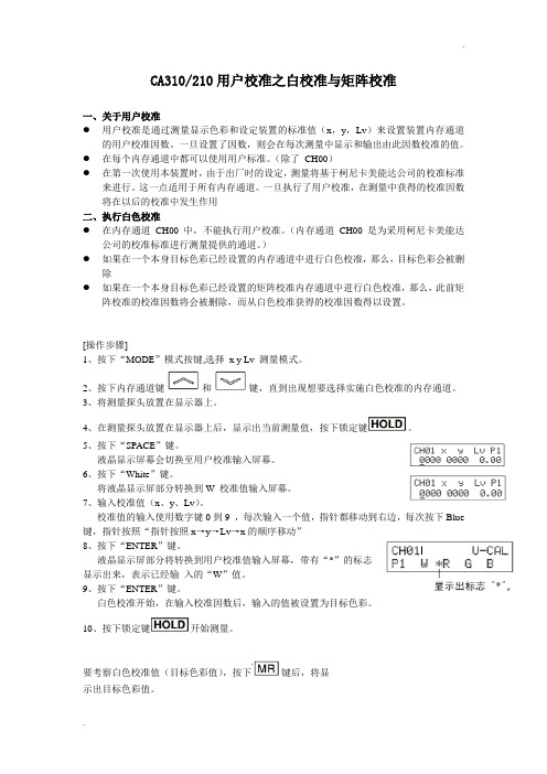
CA310/210用户校准之白校准与矩阵校准一、关于用户校准●用户校准是通过测量显示色彩和设定装置的标准值(x,y,Lv)来设置装置内存通道的用户校准因数。
一旦设置了因数,则会在每次测量中显示和输出由此因数校准的值。
●在每个内存通道中都可以使用用户标准。
(除了CH00)●在第一次使用本装置时,由于出厂时的设定,测量将基于柯尼卡美能达公司的校准标准来进行。
这一点适用于所有内存通道。
一旦执行了用户校准,在测量中获得的校准因数将在以后的校准中发生作用二、执行白色校准●在内存通道CH00 中,不能执行用户校准。
(内存通道CH00 是为采用柯尼卡美能达公司的校准标准进行测量提供的通道。
)●如果在一个本身目标色彩已经设置的内存通道中进行白色校准,那么,目标色彩会被删除●如果在一个本身目标色彩已经设置的矩阵校准内存通道中进行白色校准,那么,此前矩阵校准的校准因数将会被删除,而从白色校准获得的校准因数得以设置。
[操作步骤]1、按下“MODE”模式按键,选择x y Lv 测量模式。
2、按下内存通道键和键,直到出现想要选择实施白色校准的内存通道。
3、将测量探头放置在显示器上。
4、在测量探头放置在显示器上后,显示出当前测量值,按下锁定键。
5、按下“SPACE”键。
液晶显示屏幕会切换至用户校准输入屏幕。
6、按下“White”键。
将液晶显示屏部分转换到W 校准值输入屏幕。
7、输入校准值(x、y、Lv)。
校准值的输入使用数字键0到9 ,每次输入一个值,指针都移动到右边,每次按下Blue 键,指针按照“指针按照x→y→Lv→x的顺序移动”8、按下“ENTER”键。
液晶显示屏部分将转换到用户校准值输入屏幕,带有“*”的标志显示出来,表示已经输入的“W”值。
9、按下“ENTER”键。
白色校准开始,在输入校准因数后,输入的值被设置为目标色彩。
10、按下锁定键开始测量。
要考察白色校准值(目标色彩值),按下键后,将显示出目标色彩值。
三、执行矩阵校准●在内存通道CH00中,不能执行矩阵校准●如果在一个自身目标色彩已经设置的内存通道中,进行矩阵校准,那么,目标色彩会被删除●如果在一个已经设置白色校准的内存通道中,进行矩阵校准,那么,此前白色校准的校准因数将会被删除,而从矩阵校准获得的校准因数得以设置。
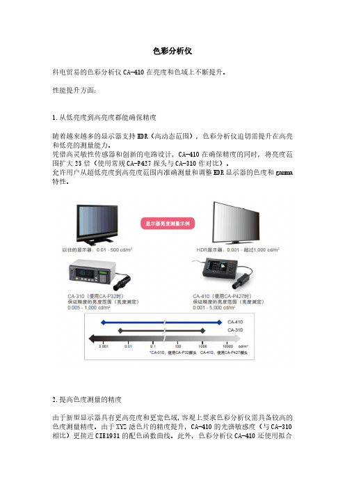
色彩分析仪科电贸易的色彩分析仪CA-410在亮度和色域上不断提升。
性能提升方面:1.从低亮度到高亮度都能确保精度随着越来越多的显示器支持HDR(高动态范围),色彩分析仪迫切需提升在高亮和低亮的测量能力。
凭借高灵敏性传感器和创新的电路设计,CA-410在确保精度的同时,将亮度范围扩大25倍(使用常规CA-P427探头与CA-310作对比)。
允许用户从超低亮度到高亮度范围内准确测量和调整HDR显示器的色度和gamma 特性。
2.提高色度测量的精度由于新型显示器具有更高亮度和更宽色域,客观上要求色彩分析仪需具备较高的色度测量精度。
由于XYZ滤色片的精度提升,CA-410的光谱敏感度(与CA-310相比)更接近CIE1931的配色函数曲线。
此外,色彩分析仪CA-410还使用拟合LED光谱的标准光源做校准,提升仪器自身的色度测量精度。
如此,用户可更准确地测量和调整显示器的色度和白平衡。
3.优化性能的产线集成方案凭借高精度的传感测量表现,Konica Minolta的CA系列色彩分析仪被许多用户集成于自动产线测量系统。
随着传感器性能提升后,CA-410可作为传感器与自动零校准系统集成,无需人工辅助,即能实现探头和PC的直接连接,进而降低集成空间要求。
此外,CA-410基本兼容旧款型号,包括软件开发包CA-SDK2的基本命令大部分兼容CA-310;探头的螺孔位置也与旧款型号一致(CA-MP410微型Mini探头除外)。
4.更丰富的测量界面为了满足CA系列客户的应用需求,CA-410可满足更多显示器产品的测量,测量gamma用时更短,可靠性更高,同时增加了对显示器低频驱动和高频频闪测量*等的支持。
*使用XYZ(宽频模式)时,会因为欠采样而造成混叠噪声的限制。
科电贸易的色彩分析仪CA-410的产品特点:1、丰富测量需求的探头系列高感探头CA-VP410(探头直径:ø10mm)CA-VP427(探头直径:ø27mm)此型号适合在高速下测量超低到高亮度范围的高端OLED显示器。

手机液晶显示屏色温矫正王裕;林魏峣;钱雪华【摘要】为了改善手机液晶显示屏白画面主观偏色的问题,本文运用了色度分析仪测量系统,对手机液晶显示屏白画面偏色矫正方法进行了研究.首先,分析了影响手机液晶显示屏白画面偏色的主要的原因,基于成本的考量,只进行后期模组段的色温矫正,借助设备厂商的色度分析仪测量手机液晶显示屏出厂时的白点坐标的分布范围,对比分析了色坐标优先(方案一)和亮度优先(方案二)两种色温矫正的方法.实验结果表明:方案一可以做到色坐标公差在±0.01以内,甚至更小(看算法的需要和设备的精度),但是无法应用于工程生产领域.方案二虽然牺牲了色温的一致性(±0.015),工厂的生产效率相比方案一提高了两倍多.综合考量成本和工厂生产效率的因素,方案二更好地满足了实际工程应用的需求.%In order to improve the color shift of the white screen of the Liquid Crystal Display (LCD) of mobile phone,this paper proposes two methods of color temperature calibration,and compares the calibration results respectively.Experimental results shows that the color coordinate method 1 can control the color coordinate tolerance within±0.01,even smaller (base on the algorithm requirement and the accuracy of the equipment).This method can't be applied to massproduction,because it takes too long time to do it.Although it sacrifices the color temperature uniformity(±0.015) by using the luminance method2,the production efficiency of the factory was nearly twice as higher as the color coordinate method 1.Taking the factors of cost and efficiency into account,the luminance method 2 is better to meet the demand of practical engineering application.【期刊名称】《液晶与显示》【年(卷),期】2017(032)012【总页数】7页(P949-955)【关键词】手机;液晶显示屏;偏色;色温矫正;生产效率;色坐标【作者】王裕;林魏峣;钱雪华【作者单位】深圳众思科技有限公司上海分公司,上海200127;深圳众思科技有限公司上海分公司,上海200127;深圳众思科技有限公司上海分公司,上海200127【正文语种】中文【中图分类】TN256手机屏幕显示的白画面偏色,即使是相同品牌相同型号所呈现出来的白画面的颜色给人主观感受都会有所不同,主要差别就在于制造液晶显示器件(LCD)本身的差异,材料特性,工艺制成的波动和参数校正的不同使得颜色表现都不可能完全一致。
显示器基础知识干货大全外接显示器障碍的诊断方法连接显示器时,有时会遇到显示器连接失败的情况,那我们该怎么找到问题所在呢?本期视频将为大家介绍几个解决外接显示器故障的方法,一起来看看吧!检查设备有无物理损坏查看设备是否存在任何物理损坏。
确保视频端口没有被任何东西阻碍,检查接口周围是否有出现损坏或丢失什么部件;查看视频电缆两端是否有出现损坏或松动。
若您的外接显示器发现任何了物理损坏,则联系我们的技术支持人员,寻求下一步的帮助。
测试端口以及电缆使用不同类型的电缆组合测试显示器端口。
查看视频的接入端口,并使用不同的电缆进行连接尝试。
若是台式机,则显卡可能只支持部分端口组合以及视频电缆。
若要查看更多详细信息,可以参考显卡用户手册。
为显示器运行自检操作确认显示器是否能通过自检。
移除接入显示器中的所有电缆大概10s左右,然后重新连接好。
通常这时候,会看到屏幕出现L(无信号)的信息。
若显示器无法感应视频信号,并且能够正常使用,会看到一个漂浮的小窗口出现在屏幕上。
更新BIOS以及驱动程序若显示器无法通过自检,则尝试通过SupportAssist更新系统BIOS以及驱动程序。
打开SupportAssist,在主页中,找到获取驱动程序和下载,点击立即运行。
SupportAssist将会自动扫描并显示所有可供更新的程序,点击下载,接着再根据屏幕提示完成后续操作。
更新显卡驱动程序打开戴尔技术支持网站,输入服务标签,选择驱动程序和下载。
然后在类别中,选择显卡进行后续更新即可。
显示器画面发灰?还有救解决方案 ?如果你是 NVIDIA 显卡用户? 在桌面右键,选择 NVIDIA 控制面板? 点击显示菜单下的更改分辨率? 在 1.选择你想要变更的显示器中选择你的显示器? 将最下方的输出动态范围更改为完全? 更改完成。
解决方案 ?如果你是 AMD 显卡用户? 在桌面右键,选择 Radeon 设置? 点击右上角的齿轮图标,选择显示器? 找到下方的像素格式,选择带有 Full RGB 的选项? 更改完成。
色坐标表示方法色彩的坐标系即表色系,国际上色彩的定量表述有孟塞尔表色系统、CIE表色系统等,各系统之间在一定条件下可以转换。
1.孟塞尔表色系孟塞尔表色系描述色彩的三个要素是,色相、彩度、明度。
色相:色彩的相貌,是区别色彩种类的名称;明度:色彩的明暗程度,即色彩的深浅差别,明度差别指同色的深浅变化,也指不同色相之间存在的明度差别;彩度:又称纯度或饱和度,指色彩的纯净程度。
孟塞尔色彩体系中色相、明度、彩度间关系如图所示。
孟塞尔表色系认为,互补的色相对比可通过调整明度差别来取得谐调,即高明度基色可配其低明度的补色来做补偿。
配色中较强的色要缩小面积,较弱的色要扩大面积。
TFT-LCD的像素大小、色层厚度等光学相关物理参数都是固定的,所以在TFT-LCD中使用孟塞尔色彩体系还原五颜六色的物体在光学和材料上很难操作。
2.RGB表色系三原色可以合成包括单色光在内的所有的颜色。
不同的待配色光达到匹配时三原色光亮度不同,用颜色方程C=R(R)+G(G)+B(B)表示,其中(R)、(G)、(B)代表代表产生混合色的红、绿、蓝三原色的单位量,R、G、B分别为匹配待配色所需要的红、绿、蓝三原色的数量,称为三刺激值。
把等能量的单色光,用三刺激值分别求出各自在RGB三维空间的坐标,得到CIE1931xy色度图。
3.XYZ表色系CIE在RGB表色系基础上,改用三个假想的原色XYZ建立了一个新的色度系统,将它匹配等能光谱的三刺激值,定名为CIE1931标准色度观察者光谱三刺激值,简称XYZ表色系。
经过变换,色度坐标均为正值,XY坐标进行归一化处理,可得到x-y色度坐标,又称CIExyY色度图,其中Y轴用于表示亮度。
4.CIExyY色度图CIExyY色度图的建立给定量分析颜色创造了条件,对CIE XYZ空间进行非线性变换空间处理,消掉XYZ的具体绝对值,把x-y坐标系迎合视觉需要修正为u-v坐标系,形成CIE LUV色度图。
建立表色系(色坐标)后,光源的颜色就可以用色空间上的某一点表示出来。
基于CA-310的手机Gamma测试
前言
消费者在购买智能手机的时候,屏幕显示性能的好坏,往往是关注的重点,但是,通常只是关注屏幕的大小、分辨率,反而容易忽略屏幕本身的发光性能。
其实在现阶段,智能手机屏幕的各大供应商在屏幕的尺寸、分辨率等这些表面参数上,已经高度同质化,而屏幕的对比度、色域及Gamma等真正影
响屏幕显示效果的但是消费者们又不易看到的这些参数上,不同品牌间还是存在较大差异的,这也就成为了不同品牌智能手机间性能、质量、价格差异的关键要素。
GAMMA检测的重要性
智能手机的便携性,注定需要使用电池,而电池性能的发展特别是电量
的延续上,在智能手机爆发性增长的几年间却并不是那么迅速,因此,如何平衡电池的电量和屏幕发光性能之间的关系,成为前期研发时的重点;其次,早先评测电视或显示器时用到的标准信号源等辅助设备,在手机上也派不上用场了,除了没有标准接口外,用到什么样的标准画面来评测也一直都是各执一词。
方案
APP在手机行业的广泛应用,给了我们以启发,下面我们就来介绍一下
这套可以快速精确地测量Gamma曲线的解决方案。
我们整个测试系统是由一套柯尼卡美能达色彩分析仪CA-310及APP构
成,另外,自备电脑和WIFI环境(见探头连接至CA-310主机è使用
USB数据线将PC与CA-310主机连接è将GAMMA检测用APP软件分
别安装至手机(APK)与PC端è被检测手机与PC连接至同一局域网(WIFI)。