WYT-AT-3-360 角位移传感器说明书
- 格式:doc
- 大小:960.00 KB
- 文档页数:2

SENSOR SWITCHItem No. RBS360104 Description ROLL BALL SWITCHVersion3Page1 of 12DateOct. 05, 2015.● FUNCTIONS1. Tilt Detecting within a 360° radius2. Vibration Detecting● APPLICATIONS1. Automatically shut off for home appliances2. Automatically shut off for Sporting equipment3. Alarm system4. Anti-theft / Anti-tamper devices5. Being motion detection6. Wake up systems for power saving7. Automatically shut off for motorbike8. EarthquakeDetecting● FEATURES1. Housing made of high insulation plastic material, free from electric conduction and rust problem.2. Sensing by phototransistors, Generating highly reliable and stable signals, not affected by oxidation or wear of metal.。
3. All plastic materials subject to industrial purpose. Resist high temperature.4. Simple ON and OFF signals, easy for design.5. Suitable to horizontal PCB.6. Tilt Angles :65° within a 360° radius.7. RoHS compliance, an ideal substitute for mercury switch.8. A more economical tilt and vibration detection option than IC design solution. 9. All made in Taiwan and examined before shipment.SENSOR SWITCHItem No. RBS360104 Description ROLL BALL SWITCHVersion3Page2 of 12 DateOct. 05, 2015.● PATENTS1. Taiwan Patent No.: M 4200332. Taiwan Patent No.: M4508173. Taiwan Patent No.: I 4514634. China Patent No.: ZL 2011 2 0339658.75. China Patent No.: ZL 2012 2 0539712.76. USA Patent No.: US 8,927,919,B2● DIMENSIONS / OPERATION / P .C.B. LAYOUT (Unit: mm, Tolerance: ±0.25mm)Table 1SENSOR SWITCHItem No. RBS360104 Description ROLL BALL SWITCHVersion3Page3 of 12 DateOct. 05, 2015.● Current/Voltage SuggestedInput Current (mA)Operating Voltage (V)Condition10 3.3 V CE =3.3VR D =200 ohmR L =15K ohm 10 5 V CE =5VR D =390 ohmR L = 22K ohm*Please refer to above Application Circuit for designing electrical circuit.● Absolute Maximum Rating (Ta=25℃)Item Symbol Rating Unit InputPower DissipationPd 75 mWReverse Voltage V R 5 V Forward CurrentI F 50 mA Peak Forward Current (*1) I FP 1 A OutputCollector Power DissipationP C 100 mW Collector Current I C 20 mA C-E Voltage V CEO 30 V E-C VoltageV ECO 5 V Operating Temperature Topr -25 ~ +85 ℃ Storage Temperature Tstg -40 ~ +85 ℃ Soldering Temperature (*2)Tsol260℃(*1) tw=100 μSec.、T =10 mSec.(*2) t=5 SecSENSOR SWITCHItem No. RBS360104 Description ROLL BALL SWITCHVersion3Page4 of 12 DateOct. 05, 2015.● Electrical Optical Characteristics (Ta=25℃)Parameter Symbol Condition Min.Typ. Max. UnitForward Voltage V F I F =20mA - 1.2 1.5 V Reverse Current I RV R =5V--10μAPeak Wavelength λp I F =10mA 940 nm Dark CurrentIceo V CE =10V - - 100μAC-E Saturation Voltage V CE (sat)I C =0.25mAI F =20mA --0.4 VLight Current I C V CE =5V I F =20mA 0.5 5 - mA Rise Time Tr I C =0.8mA V CC =30V R L =1K Ω- 5 - μsec Fall Time Tf-5-μsecSENSOR SWITCHItem No. RBS360104 Description ROLL BALL SWITCHVersion3Page5 of 12DateOct. 05, 2015.● Typical Electrical / Optical Characteristics Curves (Ta=25℃)SENSOR SWITCHItem No. RBS360104 Description ROLL BALL SWITCHVersion3Page6 of 12DateOct. 05, 2015.SENSOR SWITCHItem No. RBS360104 Description ROLL BALL SWITCHVersion3Page7 of 12 DateOct. 05, 2015.● ELECTRICAL CHARACTERISTICS 1. Contact Rating -- 2. Contact Resistance --3.Differential AngleRefer to Table 1 4. Insulation Resistance -- 5. Dielectric Strength -- 6. Capacitance --● RELIABILITY TESTTest Item StandardContentsIR Reflow -- --Operating Temp MIL-STD-202G,TEST METHOD 107G, TEST A -25°C~85°C Storage Temp MIL-STD-202G,TEST METHOD 107G, TEST A -40℃~85℃ Humidity Test MIL-STD-202G,TEST METHOD 103B40℃/95%RH Mechanical Test --2Hz, horizontal 1,000,000 times Operation LifeTest MIL-STD-883E:1016I F =20 mA, V CE =5 V TIME: 30,000 hrsSENSOR SWITCHItem No. RBS360104 Description ROLL BALL SWITCHVersion3Page8 of 12 DateOct. 05, 2015.● SOLDERING CONDITIONFollowing soldering conditions are for reference only, please use soldering information that solder paste manufacturer recommends.SENSOR SWITCHItem No. RBS360104 Description ROLL BALL SWITCHVersion3Page9 of 12 DateOct. 05, 2015.< Table of classification Reflow profile >Item Pb process Pb free processPre-heat and Soak Temperature min.(Tsmin) Temperature max.(Tsmax) Time (Tsmin to Tsmax)(ts) 100 °C 150 °C 60-120 seconds 150 °C 200 °C 60-120 seconds Average ram-up Rate(Tsmax to Tp)3 °C/second max. 3 °C/second max.Liquidous Temperature(TL)Time at Liquidous (tL) 183 °C 60-150 seconds 217 °C60-150 secondsPeak package body Temperature (Tp)*230 °C ~235 °C * 255 °C ~260 °C * Classificationtemperature(Tc)235 °C 260 °CTime(tp)** within 5 °C of the specified classification temperature (Tc)20** seconds 30** seconds Average ram-down Rate(Tp toTsmax)6 °C/second max. 6 °C/second max.Time 25 °C to peaktemperature6 minutes max. 8 minutes max.* Tolerance for peak profile temperature (Tp) is defined as a supplier minimum and a user maximum. ** Tolerance for time at peak profile temperature (tp) is defined as a supplier minimum and a user maximum.SENSOR SWITCHItem No. RBS360104 Description ROLL BALL SWITCHVersion3Page10 of 12 DateOct. 05, 2015.ProfileSENSOR SWITCHItem No. RBS360104 Description ROLL BALL SWITCHVersion3Page11 of 12 DateOct. 05, 2015.● PACKAGE Part Number Package Quantity Total Q’ty Size (mm) 1.RBS360104IC Tube 48 pcs 48 pcs 525L*10W*17.5H Inner box 84 Tubes 4,032 pcs 539L*130W*130H Carton4 Boxes16,128 pcs551L*285W*288H※ Package is shown as below for reference !Inner box CartonIC TubeSENSOR SWITCHItem No. RBS360104 Description ROLL BALL SWITCHVersion3Page12 of 12 DateOct. 05, 2015.● NOTE1. Suggestion for usage :For vibration usage or application ,we suggest to add hysteresis (on delay) for IC.2. For the continued product improvement as one of the company policy,specifications may change or update without notice. The latest information can be obtained through our sales offices. Normally, all products are supplied under our standard conditions.● PRECAUTIONS FOR USE1. If the products is intended to be used for other endurance equipment requiringhigher safety and reliability such as life support system, space and aviation devices, disaster and safety system, it’s necessary to make verification of conformity or contact us for the details before using.2. Do not clean the switch with solvent or similar substance after the solderingprocess.3. Use water-soluble flux may damage the switch.4. When the soldering temperature exceeds specifications, the switch may fall apart.5. Do not use switch in the environment of high humidity ,because such anenvironment may cause the leakage current between the terminals.6. More than the rated load may cause fire, so do not use more than the load7. In the circuit ,switch should not be near or directly connected with the magneticcomponent solder joints (for example: relays, transformers, etc.).8. To prevent damaging IR and PT, please make ESD protection, for example:wearing a conductive wrist strap or antistatic gloves during production process, or grounding machinery etc.。

3B SCIENTIFIC® PHYSICSInstrucciones de manejo05/18 ALF1 Clavija guía2 Clavijas de contacto3 Placa de cátodo4 Espiral de calefacción5 Rejilla6 Ánodo7 Espiga enchufable de 4-mm para la conexión delánodoLos tubos catódicos incandescentes sonampollas de vidrio, al vacío y de paredes finas.Manipular con cuidado: ¡riesgo de implosión!∙No someter los tubos a ningún tipo deesfuerzos físicos.∙No someter a tracción el cables deconexión.∙El tubo se debe insertar únicamente en elsoporte para tubos S (1014525).Durante el funcionamiento de los tubos, puedenpresentarse tensiones peligrosas al contacto yaltas tensiones en el campo de conexión.∙Para las conexiones sólo deben emplearsecables de experimentación de seguridad.∙Solamente efectuar las conexiones de loscircuitos con los dispositivos dealimentación eléctrica desconectados.∙Los tubos solo se pueden montar odesmontar con los dispositivos dealimentación eléctrica desconectados.Las tensiones excesivamente altas y lascorrientes o temperaturas de cátodo erróneaspueden conducir a la destrucción de los tubos.∙Respetar losparámetros operacionalesindicados.Durante el funcionamiento, el cuello del tubo secalienta∙De ser necesario, permita que los tubos seenfríen antes de desmontarlos.El funcionamiento durante largo tiempo condescarga de gas muy fuerte puede conducir aun desgaste del material de los electrodos, elcual se deposita en el tubo de vidrio conducien-do a que éste se oscurezca.El cumplimiento con las directrices referentes ala conformidad electromagnética de la UE sepuede garantizar sólo con las fuentes dealimentación recomendadas.El tríodo de gas hace posible el registro de lacurva característica I A–U A de un tiratrón, laobservación de la descarga autónoma, de ladescarga no autónoma y la entrega de energíadiscontinua de los átomos de He durante elchoque inelástico con electrones libres.El tríodo de gas es un tubo lleno de helio con unfilamento calefactor (cátodo) de tungsteno puro,una placa metálica redonda (ánodo) y una rejillade alambre entre los dos electrodos, todo dentrode una ampolla de vidrio transpa-rente. Cátodo,ánodo y la rejilla de alambre están ordenados paralelamente entre sí. Esta forma de construcción planar corresponde al símbolo tradicional de un tríodo. Una placa metálica redonda fijada en una de las entradas de alimentación del filamento calefactor hace que se cree un campo eléctrico uniforme entre el cátodo y el ánodo.Llenado de gas: NeónTensión de caldeo: ≤ 7,5 V AC/CCTensión anódica: max. 400 V CC Corriente anódica: tipo 10 mA con U A = 300 V Tensión de rejilla: max. 30 VAmpolla de vidrio: aprox. 130 mm Ø Longitud total: aprox. 260 mmPara la realización de pruebas con el tríodo de gas se necesitarán los siguientes aparatos adicionales:1 Soporte de tubos S 1014525 1 Fuente de alimentación CC 500 V@115 V 1003307 ó@230 V 1003308 2 Multímetro analogico ESCOLA 100 10135274.1 Colocación del tubo en el portatubo∙Montar y desmontar el tubo solamente con los dispositivos de alimentación eléctrica desconectados.∙Introducir el tubo en la toma hembra del portatubos presionando ligeramente hasta que las clavijas de contacto estén colocadas correctamente en la toma, asegurándose de que la clavija-guía está en la posición correcta.4.2 Retirada del tubo del portatubos.∙Para retirar el tubo, presionar desde atrás la clavija-guía con el dedo índice de la mano derecha, hasta que las clavijas de contacto queden libres. A continuación, retirar el tubo.5.1 Descarga, comprobación de losportadores de carga positivos∙Se monta el circuito de acuerdo con la fig. 1. ∙Para la comprobación de los portadores de carga positivos (Iones de Ne+) se mide la corriente I G durante la descarga de gas, manteniendo la tensión de caldeo U F en máximo, teniendo en cuenta el signo.5.2 Descarga no autónoma∙Se monta el circuito de acuerdo con la fig. 2. ∙Se mide la curva característica I A–U A(= U G) para diferentes tensiones de caldeo U F(5 V …7,5 V).Con una tensión de aprox. 25 V la corriente de ánodo I A aumenta fuertemente en el tríodo de gas. Esta subida está compañada de una luminiscencia violeta. En el transporte de cargas participan más portadores de carga que en el tríodo de alto vacío (además de los electrones de incandescencia también los iones de Ne+).5.3 Descarga autónoma∙Se monta el circuito de acuerdo con la fig. 3. ∙Se aumenta lentamente la tensión de ánodo U A y se determina la tensión de encendido U Z para la descarga del gas .∙Se reduce nuevamente la tensión de ánodo U A hasta que se detenga la descarga autónoma. Se registra la tensión de apa-gado U L.5.4 Disposición de Frank-Hertz simplificada Experimento para la comprobación de la entrega de energía discontinua durante los choques inelásticos de los electrones con los átomos de Neón. Los electrones se mueven en un campo contrario activo entre la rejilla y el ánodo. Ellos logran llegar al ánodo sólo cuando tienen suficiente energía cinética y contribuyen a la corriente I A del ánodo a masa.∙Se monta el circuito de acuerdo con la fig. 4. ∙Con una tensión contraria U R de 6 V, se aumenta lentamente la tensión de aceleración U A desde 0 hasta 70 V y midien-do al mismo tiempo la corriente de ánodo I A. ∙Se representa gráficamente la corriente de ánodo I A en dependencia con la tensión de aceleración.Hasta una tensión de aceleración de aprox. 24 V la corriente aumenta para luego caer brúscamente. Con un aumento adicional de la tensión de aceleración, la corriente ánodo vuelve a aumentar y después de otros 20 V aprox. vuelve a caer.En el curso de la corriente de ánodo se deben observar 2 máximos bien definidos. En caso de que no sea así, se reduce la un poco la tensión de caldeo.Fig. 1 Comprobación de los portadores de carga positivosFig. 2 Descarga no autónomaFig.3 Descarga autónomaFig. 4 Disposición de Franck-Hertz3B Scientific GmbH ▪ Rudorffweg 8 ▪ 21031 Hamburgo ▪ Alemania ▪ 。

上海黎升角位移传感器说明书一、产品概述上海黎升角位移传感器是一种用于测量物体角位移的设备。
该传感器通过感知物体的角度变化,并将其转化为相应的电信号,从而实现对物体运动状态的监测和控制。
适用于工业自动化、机械控制、汽车电子、仪器仪表等领域。
二、产品特点1.高精度测量:采用先进的测量技术,具备高精度的角位移测量能力,可满足各种高精度测量需求。
2.宽量程范围:可根据用户需求选择不同的量程范围,以适应不同应用场景的要求。
3.快速响应:传感器具备快速的响应速度,可实时更新所测量的角位移数据。
4.稳定可靠:采用优质材料和稳定的工艺制造,具备良好的抗干扰性和耐用性。
5.输出接口丰富:提供多种输出接口选择,包括模拟信号、数字信号、CAN总线等,方便与其他设备的连接和数据传输。
6.易于安装和使用:传感器体积小巧、安装灵活,可快速安装在机械装置上,并通过简单的操作即可实现使用。
三、技术参数1.角度测量范围:0-360度(可根据要求定制其他量程)2.角度测量精度:±0.1度3.输出信号类型:模拟信号(4-20mA、0-10V)、数字信号(RS485、TTL)、CAN总线4.工作温度范围:-40℃-+85℃5.供电电压:DC5V-24V6.防护等级:IP657. 响应时间:小于1ms8.长寿命设计:大于100万次四、安装与使用1.安装:将传感器安装在需要测量角位移的物体上,注意保持传感器与物体间的稳固连接。
2.连接:根据需要选择合适的输出接口,并将传感器与其他设备进行连接。
3.供电:将指定电压的电源与传感器进行连接,确保传感器正常工作。
4.校准:在首次使用前,需进行零位校准和量程校准,确保测量结果的准确性。
5.数据读取:根据接口类型,选择适当的数据读取方法,获取所需的角位移数据。
五、维护与保养1.定期检查:每隔一段时间,检查传感器的连接状态、外观和电气部分是否有异常。
2.清洁:用干净的棉布轻轻擦拭传感器表面,避免使用有机溶剂和腐蚀性液体。

大家知道角位移传感器是什么吗?很多人看到这个名词的第一反应是皱皱眉吧。
今天小编调查了资料跑来告诉大家一些最基本的情况,角位传感器究竟是什么呢,如何操作呢?对我们又有什么作用呢?下面就让我们带着问题看看角位移传感器的操作指南、基本原理及其应用吧。
角位移传感器操作指南:1、以传感器安装凸台定位,用螺钉、螺母或压板固紧在金属板上。
在安装传感器时,严禁对轴、壳体进行车、钻等加工,避免轴或壳体受到外界的冲击力和压力,轴的轴向和径向不允许受到冲击力和压力(静压力应小于300n)。
严禁松动传感器上的螺钉,转动固紧环位置。
2、传感器出轴与其它机件联接时应注意轴心线要保持在一直线上(包括工作状态),如轴心线有偏差存在,建议使用万向接头或波纹管等转接件,以免传感器出轴弯曲变形,损坏其他器件,从而影响使用。
3、应防止水滴、蒸气、溶剂和腐蚀性气体对传感器的侵袭,防止金属屑或其他粉末进入传感器。
4、传感器的外部接线应焊接在引出端的腰槽处,尽量不要焊在引出端的顶部。
焊接时应使用不大于45w电铬铁,焊接时间应小于5秒。
在焊接及未冷却透时不应拉动导线,以免电刷丝或整个引出端被拉出,甚至脱落。
焊接时尽量少用焊剂、焊油,时间要短,避免焊剂蒸气通过引出端进入传感器内部,导致蒸气冷却后沉积在电阻元件表面,造成等效噪声电阻变差,甚至开路。
角位移传感器基本原理:角度位移传感器原理角度传感器用来检测角度的。
它的身体中有一个孔,可以配合乐高的轴。
当连结到RCX 上时,轴每转过1/16圈,角度传感器就会计数一次。
往一个方向转动时,计数增加,转动方向改变时,计数减少。
计数与角度传感器的初始位置有关。
当初始化角度传感器时,它的计数值被设置为0,如果需要,你可以用编程把它重新复位。
角度位移传感器实例如果把角度传感器连接到马达和轮子之间的任何一根传动轴上,必须将正确的传动比算入所读的数据。
举一个有关计算的例子。
在你的机器人身上,马达以3:1的传动比与主轮连接。
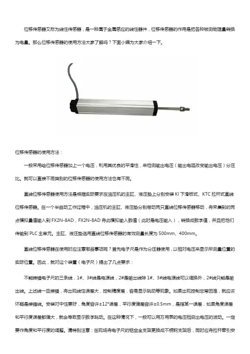
位移传感器又称为线性传感器,是一种属于金属感应的线性器件,位移传感器的作用是把各种被测物理量转换为电量。
那么位移传感器的使用方法大家了解吗?下面小编为大家介绍一下。
位移传感器的使用方法:一般采用给位移传感器加上一个电压,利用其优良的平滑性,来检测输出电压(输出电阻改变输出电压)分压比。
就可以直接不同类别的位移传感器的使用方法也有不同。
直线位移传感器使用方法是根据实际要求在油压机的主缸、液压垫上分别安装Kl下滑板式、KTC拉杆式直线位移传感器。
在一个半自动工作过程中,油压机的主缸、液压垫分别带动两只直线位移传感器移动,将采集到的两点模拟量值输入到FX2N-8AD,FX2N-8AD将此模拟输入数值(此时是电压输入),转换成数字值,并且把他们传输到PLC主单元。
主缸、液压垫选用直线位移传感器的有效测量长度为500mm、400mm。
直线位移传感器在使用时应注意哪些事项呢?首先电子尺是作为分压器使用,以相对电压来显示所测量位置的实际位置。
因此,就对这个装置(电子尺)提出了几点要求:不能接错电子尺的三条线,1#、3#线是电源线,2#是输出线除1#、3#线电源线可以调换外,2#线只能是输出线。
上述线一旦接错,将出现线性误差大,控制精度差,容易显示跳动等现象。
如果出现控制非常困难,就应该怀疑是接错线。
安装对中性要好,角度容许±12°误差,平行度偏差容许±0.5mm,是指某一误差,如果角度误差和平行度误差都偏大,就会导致显示数字跳动。
在这种情况下,一般可以用万用表的电压档测出电压的波动。
一定要作角度和平行度的调整。
请特别注意:在现场将电子尺的铝合金支架更换成不锈钢支架后,同时应将拉杆牵引安装位升高2Mm。
否则,接地问题解决了,又形成了不对中的问题,必须同时解决。
供电电源要有足够的容量,如果电源容量太小,容易发生如下情况:合模运动会导致射胶电子尺显示跳动,或熔胶运动会导致合模电子尺的显示波动。

角速度传感器说明书超小体积石英晶体角速度传感器板载型型号:EWTS82本角速度传感器的原理是将旋转时音叉震荡产生的地球偏转力(克里奥利力)转换为电信号研制成功的。
本传感器由:传感器件、音叉驱动电路和信号处理电路。
音叉由石英音叉和电极组成。
以上构成本角速度传感器。
特点:超小体积,仅有18.5mm高,10mm的长和宽。
可以安装到底板5v 供电推荐应用范围:汽车导航中的方向检测;各种工业设备的运动控制;组合导航系统;使用温度范围 -40℃~85℃低温试验 -40℃,72小时工作电压5±0.25V高温试验 85℃,120小时中心电压(-40℃~80℃) 2.5±0.4V热冲击 -40℃到85℃往复25次灵敏度 25mV/(°・S-1)温湿度循环试验 90%RH湿度,温度-10~65℃,往复5次频率响应(7Hz)〉4dB 耐久性试验 2Hz,1×107周输出电压范围0.3~4.7V输出噪声<10m Vp-p应用中的注意事项:(EWTS82 ,EWTS62 )1. 焊接(1)焊剂处理助焊剂应使用无腐蚀性的松香酒精溶液配制,尽量减少化学作用的影响。
少用助焊剂,避免渗入到传感器内部,使用蘸浸工艺时,要注意检查盛助焊剂容器的液面高低。
(2)预热预热时的维持温度不要高于100℃(3)焊接条件(推荐使用)A) 焊接材料:JIS Z 3238,H60A或H63AB) 焊接温度:250℃C) 焊接时间:5秒以内。
(4)冷却为了避免焊接过程中热累积损坏传感器,应在焊接结束后立即风冷。
(5)人工焊接A)烙铁:使用20W以下烙铁,焊接温度不要高于350℃。
B)焊接时间:3秒以内。
(6)其它确保插入仪器底板后将四个固定脚中的至少两个扭弯后焊接,并焊接牢固。
2. 清洗如果需要清洗,请参考下表,不要使用超生波类的清洗设备清洗!清洗液样例可行性水基允许酒精溶基医用乙醇允许其它汽油不允许3. 整理整理时应小心,避免跌落或强冲击。
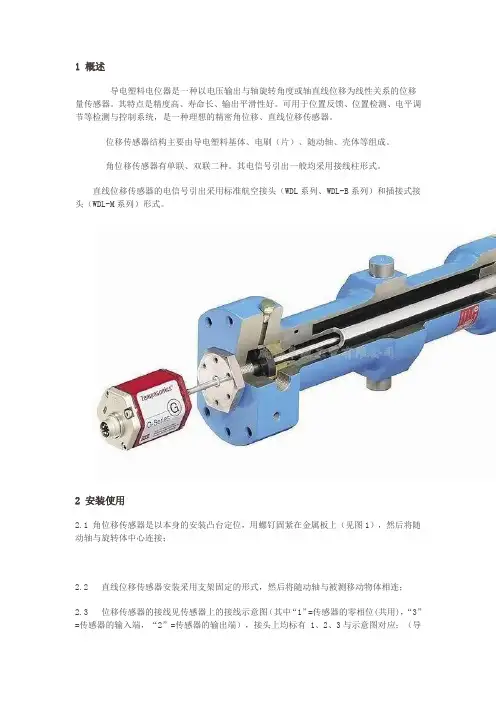
1 概述导电塑料电位器是一种以电压输出与轴旋转角度或轴直线位移为线性关系的位移量传感器。
其特点是精度高、寿命长、输出平滑性好。
可用于位置反馈、位置检测、电平调节等检测与控制系统,是一种理想的精密角位移、直线位移传感器。
位移传感器结构主要由导电塑料基体、电刷(片)、随动轴、壳体等组成。
角位移传感器有单联、双联二种。
其电信号引出一般均采用接线柱形式。
直线位移传感器的电信号引出采用标准航空接头(WDL系列、WDL-B系列)和插接式接头(WDL-M系列)形式。
2 安装使用2.1 角位移传感器是以本身的安装凸台定位,用螺钉固紧在金属板上(见图1),然后将随动轴与旋转体中心连接;2.2 直线位移传感器安装采用支架固定的形式,然后将随动轴与被测移动物体相连;2.3 位移传感器的接线见传感器上的接线示意图(其中“1”=传感器的零相位(共用),“3”=传感器的输入端,“2”=传感器的输出端),接头上均标有 1、2、3与示意图对应;(导线引出式传感器:红=1,黄=2,蓝=3)。
对带自动回复功能的M系列传感器(WDL-MT系列),零位“1”与输入端“3”对换。
2.4 位移传感器的输入与输出均为模拟量的直流电压信号,并且其输出电压的大小是由输入电压的大小来决定(如:输入5V,其整个量程的输出即为:0-5V;输入10V,其整个量程的输出即为:0-10V,以此类推)。
客户若需要电流输出,可以加配公司开发的位移电流转换器(标准两线制:24V输入,4-20mA输出)。
3 注意事项3.1 位移传感器在安装前,用户不要擅自拆卸、改装(包括撕去商标、在轴与壳体上进行加工、松动螵钉、转动固紧环位置等)。
位移传感器在安装过程中,应轻拿轻放,以免碰坏引出端;3.2 位移传感器在接入线路时,应严格按照传感器上的示意图。
特别注意“2”端严禁接入输入电压,否则烧坏传感器基体和引线;3.3 通过位移传感器的电流推荐为2mA,最大不超过1OmA;3.4 位移传感器的外部接线应焊接在引出端的腰槽处,尽量不要焊在引出端的顶部。
1 产品简介XW-ADU3603 GPS测向仪,由北京星网宇达科技开发有限公司研制。
它克服了电罗经使用成本高、操作复杂等缺点,具有操作简单、测量精度高、稳定性好等优点。
产品概述:XW-ADU3603 GPS测向仪,由定位定向单元和远程坐标解算单元两个功能部分组成。
定位定向单元由GPS接收机、测量型天线、瞄准装置、嵌入式处理器等组成。
GPS接收机作为卫星信号传感器,通过测量型天线接收GPS系统信息,嵌入式处理器解算基线与真北之间的夹角。
定位定向单元通过瞄准装置与光学探测设备连接,可以准确测量光学探测设备初始位置的方位角、俯仰角信息。
远程坐标解算单元通过输入定位定向单元测量的方位角、俯仰角以及本地坐标完成光学探测设备的初始位置标定,通过光学探测设备测量的本地坐标点与远程目标点之间方位角、俯仰角、距离实时解算出远程目标点的经度、纬度、高度信息。
XW-ADU3603定位定向单元内部集成了定位定向系统、OLED显示屏、锂电池以及操作面板等,实时显示被测物体的方位角、俯仰角、位置等信息,操作简单,使用方便,既可独立使用也可与其他系统联合使用。
在常温下锂电池可供系统持续工作4小时以上,锂电池供电与外接电源可互相切换,在切换过程中系统的正常工作不受影响。
产品主机结构采用密封设计,具有一定的防尘防淋雨功能,适用于野外环境。
产品特点:▲测量精度高、噪声小;▲动态性能好、稳定可靠;▲输出每组数据均为独立计算,无累计误差、无漂移,无需校准;▲系统响应时间短,抗干扰性强;▲定位定向单元集成了显示、电池、操作面板等,操作简单,使用方便;▲产品不仅仅具有航向输出,同时还可以作为定位导航设备。
▲具有一定的防尘防淋雨功能,适用于野外环境。
2 标准配置▲定位定向单元1台▲远程坐标解算单元1台▲充电器1个▲瞄准装置 1套▲便携箱 1个▲用户手册1本▲软件光盘1张▲合格证1份3 主要参数及技术指标表1主要参数及技术指标4硬件说明a. 远程坐标解算单元远程坐标解算单元内部嵌入以ARM为核心远程坐标解算系统,其外部有电源/输出接口,该接口为5芯航空插座,用于给主机供电和输出定位定向数据。
whiteEAN 4007841 006532infrared sensor360°max. 12 m max. 2000 W IP54 2 - 1000 lux 5 sec - 15 min Ideal 2 m energy savingmanufacture's warrantysteinel.de/garantieCEFunction descriptionThe multi-talent for indoors and outdoors. Infrared wall sensor IS 360-3, ideal for mounting under soffits, in carports, on large building facades and driveways, 3 pyro sensors for a 360° angle of coverage, reach can be set up to 12 m, selectable time and twilight threshold, detection zone can be customised with shrouds.Technical specificationsTypeMotion detectors Dimensions (Ø x H)121 x 57 mmMains power supply 220 – 240 V / 50 – 60 Hz Sensor Technology passive infrared Application, place Outdoors, IndoorsApplication, place, room outdoors, all round the building,Indoors Installation site ceiling Installation Surface wiring Switching zones 972 switching zones Electronic scalability No Mechanical scalability NoMounting height2,50 – 6,00 m Optimum mounting height 2,8 m Detection angle 360 °Angle of aperture 90 °Sneak-by guardYesCapability of masking out individualsegments YesReach, radialØ 12 m (113 m²)Twilight setting TEACH No Twilight setting 2 – 1000 lx Time setting5 s – 15 Min.Switching output 1, resistive2000 WSwitching output 1, number of LEDs/ fluorescent lamps 8 pcs.Constant-lighting control No Basic light level function NoSettings via Potentiometers With remote control No Interconnection Yes IP-rating IP54MaterialPlastic Ambient temperature -20 – 50 °C Colour white Colour, RAL9010Manufacturer's Warranty 3 years Version whitePU1, EAN4007841006532whiteEAN 4007841 006532Detection Zone Dimension DrawingLight without neutral conductor Light with neutral conductorConnection using two-circuit switch for manual and automatic operation Connection via a two-way switch for manual override and automatic operation。
360 PIR Motion Sensor alarms when motion is sensed.It is a commercial battery-powered ceiling mount sensor with a 360 degree detection range.Features• 360° detection range with 62 distinct detection zones • Range up to 40 feet in diameter • Selectable pulse count 2 or 4• Designed for commercial applications • 5 year warrantyEnroll by entering the serial number into the security panel.Alternatively, the sensor can be enrolled by placing the panel into enrollment mode, and then pulling the battery tab or tampering the device.Install by screwing two #8 screws into the ceiling, leaving 1/4inch of thread exposed. Next, slide the back plate over the screws and rotate the back plate. Screw the third #8 screw through the wall tamper into the ceiling, ensuring that the wall tamper screw is attached to something solid. Tighten all screws until snug. Then, insert the square nut into the square slit of the cover and start threading the #4 screw into the side of the cover. Close the cover and conduct a walk test. After testing, take the unit out of walk test mode and close the cover again. Finally, finish threading the #4 screw until it is snug.Use the panel’s installation guide to verify proper system setup.I N S T AL LGU I DEMounting Tips• Avoid direct sunlight• Avoid facing directly to AC or heating vents • Avoid vapor or high humidity• Avoid curtains, screens, etc. from blocking detection • Do not install outdoorsRE659 360 Motion Sensor Connect+™ EncryptedSensor FunctionsAlarm LED can be switched either “ON” or “OFF”.Pulse Count can be switched to either “2” or “4” pulsemode depending on the environmental conditions of the installation.Walk Test Jumper puts sensor in Walk Test Mode when connected or Normal Mode when not connected. The LED will light up and an alarm will be sent whenever motion is detected if the unit is in Walk Test Mode. In Normal Mode, the unit will only send an alarm every 2 minutes, and the LED will only light up if the “LED ON” jumper is connected.Detection RangePulse Count• Select “2” for normal applications.• Select “4” for use in areas where there may be movement by small animals or other objects, such as fax machines or curtains.Mounting and Jumper LocationsLEDPulse CountTroubleshootingPro TipsSave battery life by taking unit out of walk test mode after completing walk test. There is no 2 minute delay whenin walk test mode. Leaving in walk test mode willseverely decrease battery life.Light changes will cause the sensor to trip. Ensure that the detector is not placed near windows.Sudden temperature changes will cause the sensor to trip.Ensure the motion detector is not placed near heatingand cooling vents.High humidity environments can cause condensation of the detection lens. Ensure the motion detector is notinstalled in these kinds of environments. Protective film should be removed from the lens after installation.Sensor Specifications: The table below displays thefunctional frequencies of each compatible sensor.47-0047-08 • RevB • 2018-03-19Tech Support Line • (888) 88-ALULA • (888) 882-5852WARRANTYAlula will replace all non-portable products that are defective in their first five (5) years, and all portable products that are defective in their first two (2) years.IC NOTICEThis device complies with Industry Canada license-exempt RSS standard(s). Operation is subject to the following two conditions:(1) This device may not cause interference, and(2) This device must accept any interference, including interference that may cause undesired operation of the device.Le présent appareil est conforme aux cnr d’IndustrieCanada applicables aux appareils radio exempts de licence. L’exploitation est autorisée aux deux conditions suivantes:(1) L’appareil ne doit pas produire de brouillage, et(2) L’utilisateur de l’appareil doit accepter tout brouillageradioélectrique subi, même si le brouillage est susceptible d’en compromettre le fonctionnement.IC: 8310A-RE359FCC NOTICEThis device complies with Part 15 of the FCC rules. Operation is subject to the following two conditions:(1) This device may not cause harmful interference.(2) This device must accept any interference that may be received, including interference that may cause undesired operation.Changes or modifications not expressly approved by Alula could void the user’s authority to operate this equipment.FCC ID: U5X-RE359TRADEMARKSAlula and Connect+ are trademarks owned by Alula Holdings, LLC.Specifications subject to change without notice。
三鼎电子经纬仪说明书前言尊敬的用户:欢迎你购买和使用北京三鼎光电仪器有限公司的产品,向你对本公司产品的信任表示衷心的感谢~本公司自成立以来,一直把振兴测绘民族工业为己任,把生产具有国际先进水平的测绘仪器系列产品作为自身的奋斗目标。
本公司生产的测绘仪器外形美观,性能可靠,功能齐备。
使用仪器前请您提前仔细阅读本操作手册。
本公司生产的系列测绘仪器由科立达测绘仪器有限公司总代理销售。
您在使用仪器过程中如发现的问题或提出建议,请就近向销售网点反映,我们将竭诚为您服务并表示衷心感谢。
(为保持仪器的良好工作状态,建议您每年在销售网点进行一次专业的仪器保养。
)北京三鼎光电仪器有限公司二零零七年三月厂家保留对技术及产品规格进行修改的权利而不事先通知。
?I?目录(特点 ..................................................................... ........................................................................ .............. 1 12(预备事项 ..................................................................... ........................................................................ (1)2.1.预防事项 ..................................................................... .. (1)2.2.部件名称 ..................................................................... .. (2)2.3.仪器开箱和存放 ..................................................................... .. (2)2.4.电池的装卸、信息和充电 ..................................................................... . (3)2.5.仪器与机座的装卸 ..................................................................... .................................................... 4 3(键盘功能与信息显示 ..................................................................... . (5)3.1.键盘符号与功能 ..................................................................... .. (5)3.2.操作面板与操作键 ..................................................................... .................................................... 5 4(初始设置 ..................................................................... ........................................................................ (6)4.1.设置项目 ..................................................................... .. (7)4.2.设置方法 ..................................................................... .. (7)5(测量准备 ..................................................................... ........................................................................ (9)5.1.仪器的安置、对中和整平 ..................................................................... . (9)5.2.望远镜目镜调整和目标照准 ..................................................................... . (10)5.3.打开或关闭电源 ..................................................................... (10)5.4.指示竖盘指标归零(垂直置零) .................................................................... ....................... 11 6(基本测量 ..................................................................... ........................................................................ . (11)6.1.盘左/盘右观测 ..................................................................... .. (11)”(置零) .................................................................... ........................................... 12 6.2.水平角置“06.3.水平角与竖直角测量 ..................................................................... . (12)6.4.水平角锁定与解除(锁定) .................................................................... .. (12)6.5.水平角象限鸣响设置 ..................................................................... . (13)6.6.竖直角的零方向设置 ..................................................................... . (13)6.7.天顶距与垂直角的测量 ..................................................................... (13)6.8.斜率百分比 ..................................................................... .. (14)6.9.重复角度测量 ..................................................................... . (14)6.10.角度输出功能 ..................................................................... .. (15)6.11.角度存储功能 ..................................................................... .. (15)6.12.望远镜测距丝测距 ..................................................................... ................................................ 16 7(内存功能 ..................................................................... ........................................................................ . (16)7.1.查看仪器电子序列号 ..................................................................... . (16)7.2.查看内存角度数据 ..................................................................... .. (16)7.3.清除内存角度数据 ..................................................................... .. (17)7.4.向串口发送内存数据 ..................................................................... .............................................. 17 8(电子手薄连接 ..................................................................... .. (17)9(检验与校正 ..................................................................... ........................................................................189.1.长水准器 ..................................................................... (18)9.2.圆水准器 ..................................................................... (18)9.3.望远镜分划板倾斜 ..................................................................... .. (18)9.4.视准轴与横轴的垂直度(2C) ................................................................... .. (19)?II?9.5.竖盘指标零点自动补偿 ..................................................................... (19)9.6.竖盘指标差(i角)和竖盘指标零点设置 ..................................................................... .. (19)9.7.光学对中器 ..................................................................... .. (20)9.8.其他调整 ..................................................................... (21)10(技术指标 ............................................................................................................................................. .. 2211(错误代码信息表 ..................................................................... .. (24)12(附件...................................................................... ........................................................................ (25)?III?1(特点北京三鼎光电仪器有限公司生产的DT系列电子经纬仪,结构合理、美观大方、功能齐全、性能可靠、操作简单、易学易用,很容易实现仪器的所有功能,而且还具备如下特点:可与电子记录手簿联接可与科立达测绘仪器有限公司生产的电子记录手簿联机,完成野外数据的自动采集。
PRO 360 Owner's Manual2IntroductionThe Pro 360 Digital Protractor is a revolutionary measuring tool that provides an immediate, digital reading of all angles in a 360° circle. The machined aluminum frame is a rigid,light weight, ultra-precise platform that allows the state-of-the-art sensor and its microprocessor circuit to provide unsurpassed accuracy throughout the Protractor's 360° range.The Pro 360 uses an innovative liquid filled angle sensor. As the protractor is moved, the liquid seeks a new position, resulting in changes in the electrical properties of the sensor.A microprocessor analyzes the changes and calculates the numbers seen on the display.sensor3 Feature OverviewThe Pro 360 operates normally in a standard reference mode where level is displayed as 0.0°. However, a new reference point for 0.0° can easily be established by pushing the ALT ZERO button. You can also "freeze" any displayed angle on the LCD by pushing the HOLD button. The 360° range of the unit is organized into four 90° quadrants for display purposes. In each, the Pro 360 achieves an accuracy of + 0.1° at level and plumb with a maximum error of + 0.2° in between.And the Pro 360 does not need to be returned to the manufacturer or dealer for recalibration. By following the Superset® instructions in this booklet,you can test and recalibrate the Pro 360 in just a couple of minutes on site and without any special fixtures.ON/OFF buttonOperating Instructions - BatteryThe Pro 360 is powered by a 9-volt battery. A new alkaline battery will provide 500 hours of use. A 9-volt lithium battery can be used for even longer life.To extend battery life, the Pro 360 shuts off automatically when left undisturbed for five minutes (to reactivate, push the ON/OFF button). The Pro 360 also indicates when the battery is low. Change the battery when the display alternately flashes "LO bAt" with angle measure-ments. (NOTE: The Pro 360 does not display inaccurate angles due to a weak battery.)To install/replace the battery•Unscrew the battery compartment cover screw.•Remove the cover.•Install or replace the battery.•Replace the cover and tighten the screw.Do Not Overtighten45 Operating Instructions - Angle MeasuringFirst, you must make sure your unit is reading accurately by using the test on pages 8-9. If the unit fails this simple test, you must recalibrate it using Superset® (pages 10-12).To operate your Pro 360, simply push the ON/OFF button; it will begin displaying angle readings immediately. Set the Pro 360 on the surface to be measured and read the angle. (To get the most accurate reading, allow the unit to settle for 5 seconds before noting the angle.)alternate referenceplumb.Between 0° and 44.9level. Between 45°HOLD (temporarily "freezing" a reading on the display)If you need to take a measurement with the Pro 360 in an unreadable position, or if you need to temporarily lock in a reading while you record it, simply press the Hold button while measuring the angle. (Make sure the unit has been in position and still for 5 seconds.)(Superset®7 ALT ZERO(Setting an alternate reference point)ALT ZERO allows you to set any angle as a 0.0° reference point from which to take measurements. For example, you may want a surface that is actually 3° off horizontal displayed as 0° so you can measure all other angles from that benchmark.To set an alternate reference point, place the Pro 360 on the new surface and wait 5 seconds. Press the ALT ZERO button once. "Alt "will appear on the display, followedby "-0-". The Pro 360 will then display angles using the new reference. A flashing Iwill appear in the lower right hand corner of the display as long as the Pro 360 is in ALT ZERO mode.Press ALT ZERO again to return to standard reference mode. The Pro 360 also returns to standard reference when it is turned off or shuts off automatically.NOTE: You cannot activate the ALT ZERO button when the Pro 360 display is in HOLD.RecalibrationLike all measurement instruments the Pro 360 must periodically be monitored for accuracy. The Pro 360 should be tested daily with the simple procedure outlined below. If it is found to be out of calibration, it is easily recalibrated on site using Superset® - an eight-step procedure that realigns the unit through its entire 360° range and takes just a couple of minutes to perform. And Superset® doesn't require any special fixtures, tools, or expertise. Accuracy TestPerform this simple test each day before using the Pro 360. Also perform it anytime the Pro 360 has been dropped or is being used in an environment that varies more than 5°C (9° F) from the environment in which it was last calibrated. If your Pro 360 fails this test, you must recalibrate it using Superset® before using the unit further to measure angles.•Position the Pro 360 with the displayfacing you on a clean, flat horizontalsurface. It doesn't have to be exactlylevel. Wait 10 seconds so the unit iscompletely settled and note the angleon the display.89•Rotate the unit end-for-end so the display isfacing away from you. Be sure to set thePro 360 in exactly the same spot, and wait10 seconds before reading the angle that'sdisplayed.•Now roll the unit toward you so that thedisplay is facing you, but the lettering on theface of the unit is upside down. Wait 10seconds, and note the angle on the display.•Finally, rotate the unit end-for-end so thedisplay is facing away from you (thelettering should still be upside-down). Wait10 seconds and note the angle on thedisplay.•you must recalibrate (Superset®Superset®Superset® recalibrates the Pro 360 through its entire 360° range by electronically recording four horizontal and four vertical settings. It should be performed whenever the accuracy test shows a discrepancy of 0.1° or more.How to Perform Superset®Turn on the Pro 360 and place it on a flat surface. You can use any horizontal surface within 10° of level and any vertical surface within 10° of plumb to perform Superset®. You must use the same surfaces throughout the entire process.Note: Each time you reposition the Pro 360 during Superset®, wait a minimum of 10 seconds before pressing the HOLD button to advance to the next step.Starting Superset®• Press and hold the HOLD and ALT ZERO buttons simultaneously. Keep them depressed for approximately three seconds.• Release the buttons when the symbol "SUP" appears. A "0" within flashing brackets will then appear. These brackets are composed of four horizontal and four vertical segments. Note that as you proceed through the eight steps of Superset®a new segment will hold steady after you complete each step.1011 Superset® - Horizontal Settings[ 1]• Align with an edge or line - wait 10 seconds• Press HOLD button until [ 1] appears[ 2]• Rotate unit so it faces away from you, the letteringshould still be right-side up• Align with same edge or line - wait 10 seconds• Press HOLD button until [ 2] appears[ 3]• Roll unit so it faces you, the lettering should now beupside-down• Align with same edge or line - wait 10 seconds• Press HOLD button until [ 3] appears[ 4]• Rotate unit so it faces away from you, the letteringshould still be upside-down• Align with same edge or line - wait 10 seconds• Press HOLD button until [ 4] appearsYou have completed one half of Superset® (continued on next page)Superset® - Vertical Settings[ 5]• Place unit against vertical surface so it faces you, the lettering on the face ("Pro 360, etc.) should read from bottom to top• Align with an edge or line - wait 10 seconds• Press HOLD button until [ 5] appears[ 6]• Roll the unit so it faces away from you, the lettering should still read from bottom to top• Align with same edge or line - wait 10 seconds• Press HOLD button until [ 6] appears[ 7]• Rotate unit end-for-end so it faces you, the lettering should now read top to bottom• Align with same edge or line - wait 10 seconds• Press HOLD button until [ 7] appears[ 8]• Roll the unit so it faces away from you, the lettering should still read top to bottom• Align with same edge or line - wait 10 seconds• Press HOLD button. [ 8] will very briefly appear, followed immediately byregular angle measuring.Pro36Pro360 Pro 360 Pro 3601213Your Pro 360 has been Superset® back to manufacturer's spec's.Canceling Superset®You may cancel Superset® at any time during the process by turning the unit off.MaintenanceThe Pro 360 is designed to stand up to the rigors of industrial use. The following tips will ensure a long service life:• Use the "end-for-end" accuracy test daily to make sure the unit is in calibration. If it is not, recalibrate it immediately with Superset®.• Clean the Pro 360 with mild liquid soap and a damp cloth. Never immerse in water.• Do not use solvents directly on any of the Pro 360 plastic surfaces.• Store the Pro 360 away from extreme temperature: Never below -20° C (-4° F) or above 65° C (149° F).Pro 360 - Specifications Range............360° (90° x 4) Resolution.....0.1°Accuracy.......+0.1° level +10°; plumb +10°+0.2° maximum error TemperatureOperating....-5° C to 50° C (23° F to 122° F) Storage........-20° C to 65° C (-4° F to 149° F)Weight...................289 g. (10.2 oz.) Repeatability........+0.1°Cross Axis Error..Minimal Power....................9 V. Alkaline Battery Battery Life..........500 hours typical Warranty..............1 year, limited14ATTENTIONYour new digital protractor must be calibrated before use to ensure accurate readings. See your owner’s manual for Superset® calibration instructions.WARNINGDO NOT PLACE BATTERY IN BACKW ARDSOne-Year Limited WarrantyIf, within one year from the date of original purchase, the Pro 360 Digital Protractor fails to function because of defects in materials or workmanship, the manufacturer will, at its option, either repair or replace such components provided the original purchaser:1.Contacts the dealer from whom the unit was purchased for instructions;2.Follow the dealer's instructions for return of the unit;3.Submit original date and proof of purchase;4.Includes a brief explanation describing why the Pro 360 Digital Protractor is inoperable, or how it was damaged. This warranty does not cover damage resulting from accident, misuse or abuse, water, tampering, servicing performed or attempted by unauthorized agencies, units that have been modified in any fashion, or units that have not been recalibrated and maintained in accordance with the instructions in this manual.If the components do not perform as warranted herein, the original purchaser's sole remedy will be the repair or replacement of the components as provided above. In no event will the manufacturer be liable for damages, lost revenue, lost wages, lost savings, or any other incidental or consequential damages, domestic or international, rising from the purchase and use or inability to use the components even if the manufacturer has been advised of the possibility of such damages.Except as provided herein, the manufacturer makes no warranties, express or implied, including without limitation, the implied warranties of merchantability and fitness for a particular purpose, with respect to the components. All warranties for the components, express or implied, are limited to the warranty period set forth above. Some states do not allow limitations on how long an implied warranty lasts or the exclusion or limitation of incidental or consequential damages, so the above limitations or exclusions may not apply to you.This warranty gives you specific legal rights. You may also have other rights, as indicated above, which vary from state to state.85310613。
VICTOR360红外热像仪用户手册V1.1深圳市驿生胜利科技有限公司!警告、小心和注意定义!警告代表可能导致人身伤害或死亡的危险情况或行为。
!小心代表可能导致热像仪受损或数据永久丢失的情况或行为。
!注意代表对用户有用的提示信息。
重要信息–使用仪器前请阅读!警告–本仪器内置激光发射器,切勿凝视激光束。
激光规格为635nm,0.9mW,二级。
!小心–因热像仪使用非常灵敏的热感应器,因此在任何情况下(开机或关机)不得将镜头直接对准强烈幅射源(如太阳、激光束直射或反射等),否则将对热像仪造成永久性损害!!小心-运输期间必须使用原配包装箱,使用和运输过程中请勿强烈摇晃或碰撞热像仪。
!小心–热像仪储存时建议使用原配包装箱,并放置在阴凉干燥,通风无强烈电磁场的环境中。
!小心-避免油渍及各种化学物质沾污镜头表面及损伤表面。
使用完毕后,请盖上镜头盖。
!小心-为了防止数据丢失的潜在危险,请经常将数据复制(后备)于计算机中。
!注意-在精确读取数据前,热像仪可能需要3-5分钟的预热过程。
!注意-每一台热像仪出厂时都进行过温度校正,建议每年进行温度校正。
!小心-请勿擅自打开机壳或进行改装,维修事宜仅可由本公司授权人员进行。
目录!警告、小心和注意 (2)1简介 (5)1.1标准配置 (6)1.2可选配置 (7)2热像仪简介 (8)2.1功能键 (8)2.2接口 (11)3基本操作 (12)3.1电池安装及更换 (12)3.1.1电池装卸 (12)3.1.2更换电池 (13)3.2电池安全使用常识 (14)3.3快速入门 (15)3.3.1获取热像 (15)3.3.2温度测量 (15)3.3.3冻结和存储图像 (16)3.3.4回放图像 (17)3.3.5导出存储的图像 (17)4操作指南 (18)4.1操作界面描述 (18)4.1.1工作界面 (18)4.1.2主菜单 (19)4.1.3对话框 (19)4.1.4提示框 (20)4.2测温模式 (20)4.3自动/手动 (21)4.4设置 (22)4.4.1测温设置 (22)4.4.2测温修正 (23)4.4.3分析设置 (24)4.4.4时间设置 (25)4.4.5系统设置 (25)4.4.6系统信息 (27)4.4.7出厂设置 (27)4.5文件 (28)4.5.1打开 (28)4.5.2存储 (29)4.5.3存储设置 (31)4.5.4自动存储 (32)4.5.5删除 (32)4.5.6格式化 (33)5技术规格 (35)故障对策 (37)附录A (38)常用材料的比辐射率(仅供参考) (38)附录B (39)出厂设置参数表 (39)1简介感谢您选择深圳市驿生胜利科技有限公司的VICTOR360,该系列手持式红外热像仪(以下简称:热像仪)。
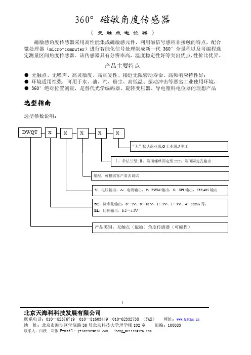
一 、概 述:
采用新型磁敏感元件,将机械转动转化为标准电信号输出,可全量程无触点的测量转动的角度变化。
在工业自动测量监控中的应用:风电、阀门控制、张力控制(卷放料、绕线机构)、机器人、医疗器械、物料位置控制,仪器仪表、记录仪表及教学演示等。
应用在航空、电力、石油、化工、纺织、印刷、船舶、冶金等行业。
尤其适用于机械变化频繁,环境恶劣,需要使用寿命长的场合。
二 、主要参数
三、参考曲线 ( 产品照片
四、 机械尺寸
传感器外壳材料:
不锈钢;
安装标记:法兰边沿刻线。
电
压值
五、接线接线准确,才通电。
导线:3×0.12, 叁芯带屏蔽,外塑材料:聚氯乙烯, 线长:2 米(普通)
红线:电源正;绿(黑)线:电源负(公共地);黄线:信号输出;金属屏蔽线(与外壳相通)。
若有干扰,请将屏蔽线与外壳良好接地。
六、测试
在装机之前,先初步检测传感器是否正常。
以确认传感器未在运输途中被损坏。
用万用表检测:
万用表用直流电流20mA档
如右图所示将万用表接入电路,
红表笔接电阻端,黑表笔接电源负极端。
直流24V 电源:正接红线,负接绿(黑)线
将转轴的铣平面端对着法兰盘上的标记位置,略调整,
找到输出为12mA,即中点位置。
逆时针旋转,至输出
4mA,即为0°,顺时针旋转至输出20mA,即为360°位置,
其它角度范围:当转动角度超出所选范围时,仍会有电信号输出,仅供参考。
七、安装调试
本产品转动方式为轴承固定。
故安装时,应保证角度传感器的轴与转动轴同轴心安装;角度传感器的壳体,通过法兰盘的螺孔,用螺丝固定。
确定工作电源的电压稳定在要求的范围内。
将转轴铣的平面端对着法兰盘上的标记点位置,略调整,找到12mA时所对应的位置,即为中点的位置,此时转动转轴, 按顺时针方向,角度增大。
八、安装注意验证确认正常的传感器,可装在测量设备上,
1 角度传感器的轴与转动轴同轴心安装。
避免轴向串动和侧面受力,以保证测量精度和使用寿命。
2 传感器是精密元件,轴不能承受轴向和径向扭力,勿敲击,以免损坏传感器及造成检测误差。
3 根据现场应用环境的需要,可加装合适的联轴器,连接安装。
以起到保护传感器的作用。
4 若在露天环境,安装时需采取防护措施和处理,轴承处防止进水,保证正常使用。
5 导线处不能受拉力。
或承重。
注意事项:
1、运输时轴做防护包装,避免轴损坏。
2、防止带电接入、移出传感器。
3、防止高压静电进入输入端,以防损坏传感器
4 冬季和夏季使用时要考虑温度差异
5 精密产品,每年最好做一次校验。
6 产品质保期:出厂后十五个月内,非使用方责任。
7 产品刻有编号。
出厂时可提供电子版产品实测数据和曲线。
8 对产品质量或服务不满意,投诉至电:010-6231 3902 传真:010-6231 3884
更多产品或新产品的信息请访问本公司网站。
或电邮索取详细资料。
北京通磁伟业传感技术有限公司100083 北京市海淀区志新路15号中原大楼408 T el:0086-10-6234 3030; 6234 4900; 6231 3902 Fax:010-6231 3884
网址: E-mail: bjtc@ ; sales@。