12 Scroll Compressors
- 格式:pdf
- 大小:119.80 KB
- 文档页数:7


GENERAL – The oil level adaptor kits described below are used to attach the Sporlan oil level con-trol to the sightglass connection on the compressor housing. In addition to the adaptor fitting, the kits contain the necessary bolts, nuts, O-ring, and sight-glass (except AOL-R-1). All Sporlan oil level controls have the same 7 bolt universal flange connection. The adaptor kits permit installing the oil level control onto compressors with various threads or mounting hole configurations.INSTALLATION– The overall procedure is to remove the existing sightglass on the compressor, install the oil level adaptor in its place, and then attach the oil level control to the adaptor. This pro-cedure requires the following steps:1. Follow the procedure suggested by the compres-sor manufacturer if the procedure is available.Otherwise the following steps are suggested.2. Shut off the power to the compressor involvedand close the suction service valve, or other valves to isolate the compressor.3. Release the refrigerant pressure in the compressorby opening an appropriate connection (for exam-ple, loosen the connection on the low pressure control). Drain the oil to a level below the bottom of the sightglass. This can be done through a drain plug, or by pulling the oil out through the filler connection with a pump.4. Remove the sightglass from the compressor. Thiswill require unbolting or unscrewing the sight-glass.5. Attach the adaptor to the compressor. TheAOL-A and AOL-C are machine threads and are sealed with an O-ring. The O-ring will seal better if it is lubricated with a light film of oil. The AOL-R-1 bolts to the compressor. See Figure 1.NOTE: The bolt holes on the sightglass and oil level control are not equally spaced. Be sure toline the holes up properly. The mark on the edge of the flange indicates the top.6. Attach the sightglass plate to the oil level control.The side of the sightglass plate with the O-ring groove goes toward the flange on the oil level con-trol. The sightglass may be attached to either arm of the oil level control. Bolts are provided, as well as an O-ring and quad ring. Since both of the mating parts contain a groove, the use of the O-ring and quad ring combination permits getting a proper seal. Tighten the bolts and nuts to approximately 6 ft.-lbs. torque.7. The oil level should always be adjusted to the levelspecified by the manufacturer. The oil level con-trol can be adjusted before use by following the instructions given in Sporlan Bulletin 110-10 or Form SD-129 supplied with the oil level control.8. Attach the oil level control (with sightglass)to the adaptor (already installed) using the bolts, nuts, and O-ring provided.9. Connect the oil supply line from the reservoir tothe flare fitting on top of the oil level control. 10. Some oil level controls incorporate an oil equal-ization fitting. If the system requires this connec-tion, connect the 3/8” flare fitting on the side of the oil level control to the oil equalization line.If the equalizer is not required, a cap must be installed.11. Refill the crankcase with oil to the proper level.Evacuate the compressor and oil level control.Open the service valve to pressurize the com-pressor and oil level system. Test for leaks.Then start the unit following the manufacturer’s recommendations.Sporlan oil level controls are listed by U nderwriters Laboratories for use with Refrigerants 134a, 22, 404A, 407C, and 507. The controls have a maximumrated pressure of 650 psi (45 bar).Page 2OIL LEVEL CONTROL ADAPTOR KITSNOTE: Mechanical oil level control not recommended for scroll compressors.Page 3To diagnose a problem of poor level control keep in mind that system problems are frequently the cause rather than a defective Oil Level Control. For example,Low oil level is caused by:• Insufficient oil in the system.• A plugged oil filter.• Oil being pulled out through the equalizer line.High oil level is caused by:• Oil returning through the suction line.• Oil that gets trapped in low spots willoften return all at once during periodso f high refrigerant velocity.• Excess oil in the system/reservoir.• Oil transferring through the equalizer line.Q Some compressor models have a smaller diameter port than the arm diameter of the oil level control. This situation can mislead the control in the amount of oil that is actually in the compressor. It is advisable the selection and adjustment of the control be reviewed in this situation. SPECIFICATIONSSD-143 / 122015© 2015 Parker Hannifin CorporationParker Hannifin CorporationSporlan Division206 Lange Drive • Washington, MO 63090 USAphone 636 239 1111fax 636 239 9130Page 4。

SCROLL COMPRESSORSSF 1-6 (1.5-5.5 kW/2-7.5 hp) / SF+ 2-22 (2.2-22 kW/3-30 hp)PURE OIL-FREE AIRAs there is no metal-to-metal contact between the compression scrolls, there is no need for oil lubrication in the compression chamber. T herefore, the scroll compression principle guarantees high-quality, oil-free air. As a result, the SF compressor isoil-free in every way.ENERGY EFFICIENCYThe SF scroll compressors, standard equipped with IE3 Premium efficiency motors, are suited for sensitive applications which require flexibility and energy efficiency. Unloaded power consumption is eliminated thanks to the simple start/stop control. Advanced scroll technology guarantees an optimalfree air delivery and low duty cycle applications.EXTREMEL Y LOW NOISE LEVELThe slow speed of the scroll compression elements ensures that the SF scroll compressors are extremely quiet. Sound levels are as low as 53 dB(a), making the SF the perfect choice for your sensitive working environment.SIMPLICITY AND RELIABILITYThe SF scroll compressors stand for simplicity and reliability. The compressor has a minimal number of moving parts, ensuring a long operating life with limited service interventions. With their integrated design, Atlas Copco’s SF scroll compressors have a minimal footprint and offereasy serviceability.PROVEN PEACE OF MINDFor over sixty years, Atlas Copco has been leading the industry in oil-free compressed air technology, drawing on vast experience and continuous technological innovations.You can rest assured at all times: severe certification and testing procedures are conducted to ensure air is suppliedto the highest standards of quality control.110438296Integrated receiverPlug and play solution, lower installation costs with 30l, 270l and 500ltank-mounted options.7Elektronikon® (SF+)Monitoring features include warning indications, maintenance schedulingand online visualization of running conditions.8Innovative designThe new compact vertical setup enables easy access for maintenance,improves cooling allowing lower working temperatures and providesvibration damping.9SF-Skid/T win• Suitable for installation at the point of useor for integration into an existing airnetwork: designed with simplicity in mind.Cooler & piping• An oversized cooler improves theperformance of the unit.• The use of aluminum pipes and thevertically oversized check valve improvereliability over lifetime and assure thehigh quality of your compressed air.10Air inlet filterHigh efficiency paper cartridge air inlet filter, eliminating dust andparticles down to 1 µm.1Automatic regulationAutomatic stop when the required working pressure is reached,avoiding unnecessary energy costs.2High efficiency scroll elementAir-cooled scroll compressor element offeringproven durability and reliability in operation,in addition to solid efficiency.IP55 Class F/IE3 motorTotally enclosed air-cooled IP55 Class F motor,complying with IE3 & Nema Premiumefficiency standards.Refrigerant dryerCompact & optimized integrated refrigerant dryer,ensuring the delivery of dry air, preventing rust andcorrosion in your compressed air network.5Silent canopyA sound insulated canopy makes extremely low noise levels as low as53 dB(A) possible, allowing to install the unit closer to the point of use.6452381® Mk5 High efficiency scroll elementAir-cooled scroll compressor elements with 8 and 10 bar variants, offering proven durability and reliability in operation, in addition to superior efficiency.3Optimized cooler & pipingThe air cooler is finetuned for improved performance, while the use of aluminum & stainless steel pipes improve reliability over lifetime and assure the high quality of compressed air.7motors, complying with IE3 Premium efficiency standards.Smart designOutstanding user-friendly design, with safety in operation & ease of serviceability in mind.8Refrigerant dryerCompact & optimized integrated refrigerant dryer ensuring the delivery of dry air, preventing rust and corrosion in the installed compressed air network.4SF Duplex• Duplex set-up with two cubicles, one/two main modules and one/two modules as back-up.• Elektronikon ® regulates each set of compressor modules via an integrated central control system.• Enclosed in sound-insulated bodywork.Silent canopyThanks to the low-noise scroll element, optimized super-silent fan and sound-insulated canopy, best in class noise levels possible are achieved.512345678ADVANCED SCROLL TECHNOLOGYAir compression is achieved by the interaction of a fixed and orbiting scroll. Air at inlet pressure enters the compression chamber at the exterior side of the scroll element. Once air is drawn in, the orbiting scroll seals off the inlet port. As the scroll continues to orbit, the air is progressively compressed into an increasingly smaller ‘pocket’. A continuous flow of compressed air leaves the scroll element through a discharge port in the center of the fixed scroll. This process is continuously repeated, resulting in the delivery of pulse-free compressed air.Variable flow technology (VFT)All SF + 8-22 multi-scroll compressors areequipped with the unique VFT control system. The VFT system, included in the Elektronikon ® controller, automatically starts and stops the scroll elements to exactly match the demands of your compressed air system. T heElektronikon ® control algorithm ensures that the system pressure is kept within a very narrow pressure band.WorkPlace Air System™ compressors: the sound of silenceA low noise level enables the compressor to be installed close to the compressed air application, minimizing the size of the air distribution system and reducing pressure loss and the potential for leakage. As the air treatment is completely integrated, the installation costs are substantially reduced, making multiple compressor installations practical and financially viable. T o ensure maximum energy efficiency, Atlas Copco offers both traditional on/off regulating systems where the air demand is constant.Cooling fan Suction chamber Suction opening Delivery opening Fixed scroll Orbiting scrollFail-safe temperature sensor for unit protection Compression chamber12345678Current ISO 8573-1 (2010) classes (the five main classes and the associated maximum concentration in total oil content).CLASS ZERO: THEINDUSTRY STANDARDOil-free air is used in all kinds of industries where air quality is paramount. These applications include food and beverage processing, pharmaceutical manufacturing, petrochemical processing, wastewater treatment, and many more. I n these critical environments, contamination by even the smallest quantities of oil can result in costly production downtime and product spoilage.First in oil-free air technologyOver the past 60 years Atlas Copco has pioneered the development of oil-free air technology, resulting in a range of air compressors that provide 100% pure, oil-free air. T hrough continuous research and development, Atlas Copco achieved a new milestone, setting the standard for air purity as the first manufacturer to be awarded ISO 8573-1 Class 0 certification.Eliminating any riskAs industry leader committed to meeting the needs of the most demanding customers, Atlas Copco requested the renowned T ÜV institute to type-test its range of oil-free compressors. Using the most rigorous testing methodologies available, all possible oil forms were measured across a range of temperatures andpressures. T he T ÜV found no traces of oil at all in the output air stream. T hus Atlas Copco is the first compressor manufacturer to receive Class 0 certification, according to ISO 8573-1 Class 0 Ed. 3 2010 specifications.® controller, while the SF +Elektronikon ® Graphic.Improved user-friendliness• 3.5-inch high-definition color display with clear pictograms and extra 4th LED indicator for service.• Graphical display of key parameters (day, week, month) and 32 language settings.• Internet-based compressor visualization using a simple Ethernet connection.• Graphical indication Serviceplan, remote control and connectivity functions.• Software upgrade available to control up to 6 compressors by installing the optional integrated compressor controller.4 modules61218183 modules2 modules1 moduleTECHNICAL SPECIFICATIONS* Free Air Delivery measured according ISO 1217 ed. 4 2009, Annex C.** Mean sound pressure level measured according to ISO 2151, with an uncertainty of 3 dB(A).Weights of the pack & floor-mounted units are shown in the chart.DIMENSIONSLWHL WHL WHL WH•: Optional- : Not availableCOMMITTED TO SUSTAINABLE PRODUCTIVITYWe stand by our responsibilities towards our customers, towards the environment and the people around us. We make performance stand the test of time. T his is what we call – Sustainable Productivity./sf2935 0844 48 © 2014, A t l a s C o p c o A i r p o w e r N V , B e l g i u m . A l l r i g h t s r e s。
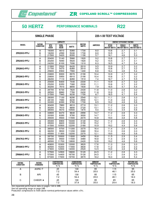
50 HERTZ R22PERFORMANCE NOMINALSSINGLE PHASE220-1-50 TEST VOLTAGECAPACITY ENERGY EFFICIENCY RATINGRATING MOTORMODEL AMPERESBTU KCAL BTUH KCALH WATTS CONDITION WATTSWATTSHOUR HOUR MOTOR WATTS MOTOR WATTS MOTOR WATTS A183004610536017308.010.6 2.7 3.1ZR22K3-PFJ B182004590533017308.010.5 2.7 3.1 C21500542063001190 5.718.1 4.6 5.3A204005140598019209.210.6 2.7 3.1ZR24K3-PFJ B202005090592019209.210.5 2.7 3.1 C24200610070901310 6.318.5 4.7 5.4A219005520642020109.510.9 2.7 3.2ZR26K3-PFJ B217005470636020109.510.8 2.7 3.2 C25800650075601400 6.818.4 4.6 5.4A2380060006970219010.410.9 2.7 3.2ZR28K3-PFJ B2360059506910219010.410.8 2.7 3.2 C282007110826015107.418.7 4.7 5.5A2540064007440233011.110.9 2.7 3.2ZR30K3-PFJ B2520063507380233011.110.8 2.7 3.2 C302007610885016307.918.5 4.7 5.4A2670067307820243011.811.0 2.8 3.2ZR32K3-PFJ B2650066807760243011.810.9 2.7 3.2 C315007940923017008.718.5 4.7 5.4A2830071308290254012.111.1 2.8 3.3ZR34K3-PFJ B2810070808230255012.111.0 2.8 3.2 C333008390976017308.519.2 4.8 5.6A3040076608910271013.111.2 2.8 3.3ZR36K3-PFJ B3020076108850272013.111.1 2.8 3.3 C3600090701050018709.419.3 4.9 5.6A3360084709840299014.711.2 2.8 3.3ZR40K3-PFJ B3330083909760300014.711.1 2.8 3.2 C39400993011500207010.819.0 4.8 5.6A35300890010300314015.211.2 2.8 3.3ZR42K3-PFJ B35000882010300315015.211.1 2.8 3.3 C415001050012200216010.919.2 4.9 5.6A38500970011300337016.411.4 2.9 3.4ZR45K3-PFJ B38200963011200338016.411.3 2.8 3.3 C450001130013200237012.119.0 4.8 5.6A397001000011600345016.811.5 2.9 3.4ZR47K3-PFJ B39400993011500346016.811.4 2.9 3.3 C465001170013600242012.619.2 4.8 5.6A408001030012000362017.611.3 2.8 3.3ZR48K3-PFJ B405001020011900363017.611.2 2.8 3.3 C478001200014000252013.519.0 4.8 5.6A575001450016800512024.511.2 2.8 3.3ZR68KC-PFJ B570001440016700513024.511.1 2.8 3.3 C673001700019700367018.218.3 4.6 5.4PERFORMANCE NOMINALS50 HERTZR22THREE PHASETEST VOLTAGECAPACITYENERGY EFFICIENCY RATINGRATING MOTOR MODELAMPERES*BTU KCAL BTUH KCALH WATTS CONDITIONWATTSWATTSHOURHOURMOTOR WATTS MOTOR WATTSMOTOR WATTSA 18300461053601770 5.5/3.210.3 2.6 3.0ZR22K3-TF5/DB 18200459053301770 5.5/3.210.3 2.6 3.0C 21500542063001170 4.3/2.518.4 4.6 5.4A 20400514059801920 6.0/3.510.6 2.7 3.1ZR24K3-TF5/DB 20200509059201920 6.0/3.510.5 2.7 3.1C 24200610070901250 4.7/2.719.4 4.9 5.7A 21900552064202010 6.6/3.810.9 2.7 3.2ZR26K3-TF5/DB 21700547063602010 6.6/3.810.8 2.7 3.2C 25800650075601360 5.0/2.919.0 4.8 5.6A 23800600069702150 6.9/4.011.1 2.8 3.2ZR28K3-TF5/DB 23600595069102150 6.9/4.011.0 2.8 3.2C 28200711082601450 5.4/3.119.4 4.9 5.7A 254006400744022907.3/4.211.1 2.8 3.2ZR30K3-TF5/DB 252006350738022907.3/4.211.0 2.8 3.2C 30200761088501540 5.5/3.219.6 4.9 5.7A 267006730782024307.6/4.411.0 2.8 3.2ZR32K3-TF5/DB 265006680776024307.6/4.410.9 2.7 3.2C 31500794092301640 5.9/3.419.2 4.8 5.6A 283007130829025007.9/4.611.3 2.9 3.3ZR34K3-TF5/DB 281007080823025007.9/4.611.2 2.8 3.3C 33400842097901700 6.2/3.619.6 5.0 5.8A 304007660891026908.3/4.811.3 2.8 3.3ZR36K3-TF5/DB 302007610885027008.3/4.811.2 2.8 3.3C 360009070105001810 6.4/3.719.9 5.0 5.8A 336008470984029609.2/5.311.4 2.9 3.3ZR40K3-TF5/DB 333008390976029709.2/5.311.2 2.8 3.3C 3940099301150019907.1/4.119.8 5.0 5.8A 3530089001030031009.5/5.511.4 2.9 3.3ZR42K3-TF5/DB 3500088201030031109.5/5.511.3 2.8 3.3C41500105001220020807.4/4.320.05.05.9*Ampere values shown are at 220 volts/380 volts.220-3-50 (TF5)380-3-50 (TFD)PERFORMANCE NOMINALS50 HERTZR22THREE PHASETEST VOLTAGECAPACITYENERGY EFFICIENCY RATINGRATING MOTOR MODELAMPERES*BTU KCAL BTUH KCALH WATTS CONDITIONWATTSWATTSHOURHOURMOTOR WATTS MOTOR WATTSMOTOR WATTSA 38200963011200331010.5/6.111.5 2.9 3.4ZR45KC-TF5/DB 37900955011100332010.5/6.111.4 2.9 3.3C 44500112001300022908.3/4.819.4 4.9 5.7A 397001000011600342010.9/6.311.6 2.9 3.4ZR47KC-TF5/DB 39400993011500343010.9/6.311.5 2.9 3.4C 46300117001360023408.8/5.119.8 5.0 5.8A 408001030012000360011.2/6.511.3 2.9 3.3ZR48KC-TF5/DB 405001020011900361011.2/6.511.2 2.8 3.3C 47800120001400024908.6/5.019.2 4.8 5.6A 454001140013300397012.6/7.311.4 2.9 3.4ZR54KC-TF5/DB 450001130013200398012.6/7.311.3 2.8 3.3C 530001340015500282010.0/5.818.8 4.8 5.5A 479001210014000416013.5/7.811.5 2.9 3.4ZR57KC-TF5/DB 475001200013900417013.5/7.811.4 2.9 3.3C 560001410016400295010.4/6.019.0 4.8 5.6A 514001300015100442014.0/8.111.6 2.9 3.4ZR61KC-TF5/DB 510001290014900443014.0/8.111.5 2.9 3.4C 600001510017600317011.1/6.418.9 4.8 5.6A 580001460017000495014.9/8.611.7 2.9 3.4ZR68KC-TF5/DB 575001450016800496014.9/8.611.6 2.9 3.4C 680001710019900343011.4/6.619.8 5.0 5.8A 610001540017900517015.4/8.911.8 3.0 3.5ZR72KC-TF5/DB 605001520017700518015.4/8.911.7 2.9 3.4C 715001800020900361011.6/6.719.8 5.0 5.8A 685001730020100580018.1/10.511.8 3.0 3.5ZR81KC-TF5/DB 680001710019900581018.1/10.511.7 2.9 3.4C795002000023300414015.2/8.819.24.85.6*Ampere values shown are at 220 volts/380 volts.220-3-50 (TF5)380-3-50 (TFD)APPLICATION NOTES•The Copeland Scroll Compressor has been under developmentat Copeland since 1979 and is the most efficient and durable compressor we have ever developed for residential air condi-tioning and heat pump applications.Copeland Scroll compres-sors have fewer moving parts and no dynamic suction or dis-charge valves.In addition, they offer very low vibration and sound levels and are very tolerant to stresses caused by liquid slugging, flooded starts, and debris commonly found in resi-dential split air conditioning and heat pump systems.•These Copeland Scrolls include a higher range of capacities and more electrical options than the earlier ZR1 models.Inaddition, there are several operating characteristics and design features which are different from the ZR1 models.•The Copeland Scroll is a new type of compressor and there are a number of application characteristics which are different from the traditional reciprocating compressor.These are fully detailed in the Application Bulletin AE4-1312.•The motor protector used in these ZR compressors is mounted internally and its proven design is the result of extensive labo-ratory research and field testing.It protects the motor from maximum operating overload, both high and low voltage, and loss of refrigerant charge.It is both current and heat sensing.The single phase protector protects both the run and start windings.The three phase protector is wired at the connection point of the motor's three legs.Therefore, the protector protects all three legs and if a problem occurs with one or more of them,the protector breaks all three phases.•The rotational speed of the compressor is:•50 Hertz 2900 RPM•No crankcase heater is required for single phase compressors.•A crankcase heater is required for three phase compressors when the system charge exceeds the compressor refrigerant charge limit shown below, and no accumulator is used, or when the charge exceeds this limit and an accumulator cannot be piped to provide free liquid drainage into the accumulator dur-ing the off cycle.•ZR22 to ZR488 pounds (3.6 Kg)••Since Copeland Scroll Compressors have very high volumetricefficiency, their displacements are lower than for comparable capacity reciprocating compressors.As a result, Copeland mends that the capacity rating on reversing valves be no more than 1.5 to 2 times the nominal capacity of the compres-sor with which it will be used in order to ensure proper opera-tion of the reversing valve under all operating conditions.•The compressor has the approval to operate as a heat pump within the operating range.Its increased bearing surfaces and improved lubrication system provide excellent reliability even when operated at the heat pump's higher compression ratios.•Low ambient cut-outs are not required to limit heat pump operation.•These Scroll Compressors have internal pressure relief valves which open at a discharge to suction differential pressure of 375 to 450 psi.•No start assist devices are required.Due to the inherent design of the Scroll, the internal compression components always start unloaded even if system pressures are not balanced.•Rated load amps is the value used for contactor and other elec-trical component selection.It is calculated by dividing the max-imum continuous current that the compressor draws under the condition of maximum load operation and the lowest operating voltage by 1.4.See Application Bulletin AE 9-1154 for a detailed explanation.•Complete 50 Hertz performance curves are available in the units as follows for all models:•CapacityBTU/Hr •Power Input Watts •CurrentAmps •EfficiencyBTUH/Watt •Copeland has compiled a book of compressor Application Bulletins.Please see the following bulletins, from the book, for more ZR compressor application information as entitled below:Mounting Parts ............................AE 4-1111Application Guidelines ....................AE 4-1312Nameplate Amperage Rating ..............AE 9-1154Approved range is based on 20F°(11.1C°) of superheat.PERFORMANCE NOMINALS50 HERTZR22THREE PHASETEST VOLTAGECAPACITYENERGY EFFICIENCY RATINGRATING MOTOR MODELAMPERES*BTU KCAL BTUH KCALH WATTS CONDITIONWATTSWATTSHOURHOURMOTOR WATTS MOTOR WATTS MOTOR WATTSA 700001760020500613020.5/11.911.4 2.9 3.3ZR84KC-TF5/DB 694001750020300614020.5/11.911.3 2.9 3.3C 814002050023900444017.0/9.818.3 4.6 5.4A 804002030023600687021.4/12.411.7 3.0 3.4ZR94KC-TF5/DB 798002010023400688021.4/12.411.6 2.9 3.4C 941002370027600491016.8/9.719.2 4.8 5.6A 917002310026900781025.3/13.711.7 3.0 3.4ZR108KC-TF5/DB 910002290026700783025.3/13.711.6 2.9 3.4C 1070002700031400573020.8/11.018.7 4.7 5.5A 1054002660030900911027.5/15.911.6 2.9 3.4ZR125KC-TF5/DB 1046002640030600913027.5/15.911.5 2.9 3.4C 1222003080035800663021.6/12.518.4 4.6 5.4A 11980030200351001018034.7/20.111.8 3.0 3.4ZR144KC-TF5/DB 11880029900348001020034.7/20.111.6 2.9 3.4C1407003550041200750027.3/15.818.84.75.5*Ampere values shown are at 220 volts/380 volts.220-3-50 (TF5)380-3-50 (TFD)PERFORMANCE DATA50 HERTZ R2220°F (11.1°C) Superheat15°F (8.3°C) Subcooling95°F (35°C) Ambient (Air Over)200/220-3-50 (TF5)Rated Voltage 220-3-50 (TF5)Test Voltage380/420-3-50 (TFD)380-3-50 (TFD)ZR84KC-TF5/TFD R22CAPACITY(BTU/HOUR)CONDENSING TEMPERATURE EVAPORATING TEMPERATURE °F/°C°F/°C– 10010203040455055– 23.3– 17.8– 12.2– 6.7– 1.1 4.47.210.012.8 100 (37.8)208002930038600489006060074000814008930097800 120 (48.9)31700424005400066800737008110089000 140 (60.0)4510057900647007180079200 CAPACITY(KCAL/HOUR)°F/°C– 10010203040455055– 23.3– 17.8– 12.2– 6.7– 1.1 4.47.210.012.8 100 (37.8)524073809730123001530018600205002250024600 120 (48.9)7990107001360016800186002040022400 140 (60.0)1140014600163001810020000 CAPACITY(WATTS)°F/°C– 10010203040455055– 23.3– 17.8– 12.2– 6.7– 1.1 4.47.210.012.8 100 (37.8)6090858011300143001780021700239002620028700 120 (48.9)9290124001580019600216002380026100 140 (60.0)1320017000190002100023200 POWER (MOTOR WATTS)°F/°C– 10010203040455055– 23.3– 17.8– 12.2– 6.7– 1.1 4.47.210.012.8 100 (37.8)437043604360437043804420444044704510 120 (48.9)5570552054905490549055105530 140 (60.0)70006930690068906880 ZR94KC-TF5/TFD R22CAPACITY(BTU/HOUR)CONDENSING TEMPERATURE EVAPORATING TEMPERATURE °F/°C°F/°C– 10010203040455055– 23.3– 17.8– 12.2– 6.7– 1.1 4.47.210.012.8 100 (37.8)24700342004470056600701008560094100103200112900 120 (48.9)380004950062400770008500093600102700 140 (60.0)5260066400740008200090600 CAPACITY(KCAL/HOUR)°F/°C– 10010203040455055– 23.3– 17.8– 12.2– 6.7– 1.1 4.47.210.012.8 100 (37.8)6220862011300143001770021600237002600028500 120 (48.9)9580125001570019400214002360025900 140 (60.0)1330016700186002070022800 CAPACITY(WATTS)°F/°C– 10010203040455055– 23.3– 17.8– 12.2– 6.7– 1.1 4.47.210.012.8 100 (37.8)72401000013100166002050025100276003020033100 120 (48.9)11100145001830022600249002740030100 140 (60.0)1540019500217002400026500 POWER (MOTOR WATTS)°F/°C– 10010203040455055– 23.3– 17.8– 12.2– 6.7– 1.1 4.47.210.012.8PERFORMANCE DATA50 HERTZ R2220°F (11.1°C) Superheat15°F (8.3°C) Subcooling95°F (35°C) Ambient (Air Over)200/220-3-50 (TF5)Rated Voltage 220-3-50 (TF5)Test Voltage380/420-3-50 (TFD)380-3-50 (TFD)ZR108KC-TF5/TFD R22CAPACITY(BTU/HOUR)CONDENSING TEMPERATURE EVAPORATING TEMPERATURE °F/°C°F/°C– 10010203040455055– 23.3– 17.8– 12.2– 6.7– 1.1 4.47.210.012.8 100 (37.8)303003990051300644007970097300107000117300128300 120 (48.9)4500057300714008770096700106200116400 140 (60.0)61800768008500093800103200 CAPACITY(KCAL/HOUR)°F/°C– 10010203040455055– 23.3– 17.8– 12.2– 6.7– 1.1 4.47.210.012.8 100 (37.8)76401010012900162002010024500270002960032300 120 (48.9)11300144001800022100244002680029300 140 (60.0)1560019400214002360026000 CAPACITY(WATTS)°F/°C– 10010203040455055– 23.3– 17.8– 12.2– 6.7– 1.1 4.47.210.012.8 100 (37.8)88801170015000189002340028500314003440037600 120 (48.9)13200168002090025700283003110034100 140 (60.0)1810022500249002750030200 POWER (MOTOR WATTS)°F/°C– 10010203040455055– 23.3– 17.8– 12.2– 6.7– 1.1 4.47.210.012.8 100 (37.8)527053705450550055705670573058105900 120 (48.9)6860689069306980702070707130 140 (60.0)88008790879088008830 ZR125KC-TF5/TFD R22CAPACITY(BTU/HOUR)CONDENSING TEMPERATURE EVAPORATING TEMPERATURE °F/°C°F/°C– 10010203040455055– 23.3– 17.8– 12.2– 6.7– 1.1 4.47.210.012.8 100 (37.8)3670046900595007450091900111500122200133500145300 120 (48.9)529006650082500100800110800121300132400 140 (60.0)715008840097700107500117900 CAPACITY(KCAL/HOUR)°F/°C– 10010203040455055– 23.3– 17.8– 12.2– 6.7– 1.1 4.47.210.012.8 100 (37.8)92501180015000188002320028100308003360036600 120 (48.9)13300168002080025400279003060033400 140 (60.0)1800022300246002710029700 CAPACITY(WATTS)°F/°C– 10010203040455055– 23.3– 17.8– 12.2– 6.7– 1.1 4.47.210.012.8 100 (37.8)108001370017400218002690032700358003910042600 120 (48.9)15500195002420029500325003550038800 140 (60.0)2090025900286003150034500 POWER (MOTOR WATTS)°F/°C– 10010203040455055– 23.3– 17.8– 12.2– 6.7– 1.1 4.47.210.012.8PERFORMANCE DATA50 HERTZ R22/407C 20°F (11.1°C) Superheat15°F (8.3°C) Subcooling95°F (35°C) Ambient (Air Over)200/220-3-50 (TF5)Rated Voltage 220-3-50 (TF5)Test Voltage380/420-3-50 (TFD)380-3-50 (TFD)ZR144KC-TF5/TFD R22CAPACITY(BTU/HOUR)CONDENSING TEMPERATURE EVAPORATING TEMPERATURE °F/°C°F/°C– 10010203040455055– 23.3– 17.8– 12.2– 6.7– 1.1 4.47.210.012.8 100 (37.8)42100539006870086200106200128600140700153200166300 120 (48.9)597007550094200115300126800138800151400 140 (60.0)8010099500110200121400133300 CAPACITY(KCAL/HOUR)°F/°C– 10010203040455055– 23.3– 17.8– 12.2– 6.7– 1.1 4.47.210.012.8 100 (37.8)106001360017300217002680032400355003860041900 120 (48.9)15000190002370029100320003500038200 140 (60.0)2020025100278003060033600 CAPACITY(WATTS)°F/°C– 10010203040455055– 23.3– 17.8– 12.2– 6.7– 1.1 4.47.210.012.8 100 (37.8)123001580020100253003110037700412004490048700 120 (48.9)17500221002760033800372004070044400 140 (60.0)2350029200323003560039100 POWER (MOTOR WATTS)°F/°C– 10010203040455055– 23.3– 17.8– 12.2– 6.7– 1.1 4.47.210.012.8 100 (37.8)680070107120719072707400750076307800 120 (48.9)8900899090409110916092409340 140 (60.0)1135011380114001143011480 ZR84KCE-TF5/TFD R407C CAPACITY(BTU/HOUR)CONDENSING TEMPERATURE EVAPORATING TEMPERATURE °F/°C°F/°C– 10010203040455055– 23.3– 17.8– 12.2– 6.7– 1.1 4.47.210.012.8 100 (37.8)2130030100397005040062500761008360091500100000PERFORMANCE NOMINALS50 HERTZR22THREE PHASETEST VOLTAGECAPACITYENERGY EFFICIENCY RATINGRATING MOTOR MODELAMPERES*BTU KCAL BTUH KCALH WATTS CONDITIONWATTSWATTSHOURHOURMOTOR WATTS MOTOR WATTS MOTOR WATTSA 741001870021700661025.0/22.7/13.1/10.011.2 2.8 3.3ZR90K3-TWC/R/D/EB 735001850021500662025.0/22.7/13.1/10.011.1 2.8 3.2C 860002170025200474021.0/19.1/11.1/8.418.1 4.6 5.3A 903002280026500792028.6/26.0/15.1/11.411.4 2.9 3.3ZR11M3-TWC/R/D/EB 896002260026300794028.6/26.0/15.1/11.411.3 2.8 3.3C 1060002670031100559023.2/21.1/12.2/9.319.0 4.8 5.6A 1047002640030700909033.0/30.0/17.4/13.211.5 2.9 3.4ZR12M3-TWC/R/D/EB 1039002620030400911033.0/30.0/17.4/13.211.4 2.9 3.3C 1227003090036000642026.8/24.4/14.1/10.719.1 4.8 5.6A 12870032400377001118038.2/34.7/20.1/15.311.5 2.9 3.4ZR16M3-TWC/R/D/EB 12770032200374001120038.2/34.7/20.1/15.311.4 2.9 3.3C 1500003780044000810030.4/27.6/16.0/12.218.5 4.7 5.4A 15800039800463001355047.4/43.1/25.0/19.011.7 2.9 3.4ZR19M3-TWC/R/D/EB 15670039500459001358047.4/43.1/25.0/19.011.5 2.9 3.4C1827004600053500956037.2/33.8/19.6/14.919.14.85.6* Ampere values shown are at 200 volts/220 volts/380 volts/500 volts.200-3-50 (TWC)220-3-50 (TWR)380-3-50 (TWD)500-3-50 (TWE)MECHANICAL SPECIFICATIONSZR90K3/K3E 7.57.319737.0889.52055.6119.920.8625.1893.0ZR11M3/M3E 98.790885.11068.22056.7144.025.0630.2493.0ZR12M3/M3E 1010.101016.51226.82057.5165.528.7834.7393.0ZR16M3/M3E 1312.471255.61515.32279.7204.335.5542.90103.0ZR19M3/M3E1514.761486.21793.824711.2241.942.0750.78112.0COMPRESSOR NET WEIGHT POUNDS KILOGRAMSELECTRICAL SPECIFICATIONSVOLTAGE CODE TWR TWC TW7TWD TWE NOMINAL VOLTAGE-220/240-3-50200-3-50380/420-3-50500-3-50PHASE-HERTZ 208/230-3-60380-3-60460-3-60575-3-60VOLTAGE RANGE50 HERTZ 198-264180-220342-462450-55060 HERTZ187-253342-418414-506518-633TWR TWC TW7TWD TWE RATED LOCKED RATED LOCKED RATED LOCKED RATED LOCKED RATED LOCKED MODELLOAD ROTOR LOAD ROTOR LOAD ROTOR LOAD ROTOR LOAD ROTOR AMPS AMPS AMPS AMPS AMPS AMPS AMPS AMPS AMPS AMPS RLALRARLALRARLALRARLALRARLALRAREFRIGERANT R22R407C R134a ALL R22R407C R134a ALL R22R407C R134a ALL R22R407CR134a ALL R22R407C R134a ZR90K3/K3E 23.626.026.017427.230.230.218917.117.117.111214.314.614.69910.411.811.8ZR11M3/M3E 30.530.530.522134.334.334.323221.321.321.314417.517.517.512513.213.213.2 ZR12M3/M3E 35.035.035.023538.637.537.527826.126.126.115118.918.918.912715.715.715.7ZR16M3/M3E 44.244.244.229347.150.450.435028.728.728.719525282816719.919.919.9ZR19M3/M3E52.252.552.534555.256.756.742537.538.338.323927.233.133.119824.324.324.3MODELNOMINAL HP KWIN 3CM 3CUBIC INCHES PER REVOLUTION CUBIC CENTIMETERS PER REVOLUTIONCFH M 3/HRCUBIC FEET PER HOUR CUBIC METERS PER HOUR 50 HERTZ 60 HERTZ 2900 RPM3500 RPMALL 74100 100 125148PERFORMANCE DATA50 HERTZ R2220°F (11.1°C) Superheat15°F (8.3°C) Subcooling95°F (35°C) Ambient (Air Over)200-3-50(TWC)380/420-3-50(TWD)Rated Voltage 200-3-50 (TWC)380-3-50 (TWD)Test Voltage220/240-3-50(TWR)500-3-50(TWE)220-3-50 (TWR)500-3-50 (TWE)ZR12M3-TWC/TWR/TWD/TWE R22CAPACITY(BTU/HOUR)CONDENSING TEMPERATURE EVAPORATING TEMPERATURE °F/°C°F/°C– 10010203040455055– 23.3– 17.8– 12.2– 6.7– 1.1 4.47.210.012.8 100 (37.8)3340045300586007380091200111000123000135000148000 120 (48.9)516006570081700100000110000121000133000 140 (60.0)715008800097200107000118000 CAPACITY(KCAL/HOUR)°F/°C– 10010203040455055– 23.3– 17.8– 12.2– 6.7– 1.1 4.47.210.012.8 100 (37.8)84201140014800186002300028100309003400037300 120 (48.9)13000165002060025200278003060033600 140 (60.0)1800022200245002700029700 CAPACITY(WATTS)°F/°C– 10010203040455055– 23.3– 17.8– 12.2– 6.7– 1.1 4.47.210.012.8 100 (37.8)98001330017200216002670032600359003950043300 120 (48.9)15100192002390029300323003560039000 140 (60.0)2090025800285003140034500 POWER (MOTOR WATTS)°F/°C– 10010203040455055– 23.3– 17.8– 12.2– 6.7– 1.1 4.47.210.012.8 100 (37.8)628064006450646064506430642064206430 120 (48.9)8060812081408130811081008090 140 (60.0)1020010200102001020010200 ZR16M3-TWC/TWR/TWD/TWE R22CAPACITY(BTU/HOUR)CONDENSING TEMPERATURE EVAPORATING TEMPERATURE °F/°C°F/°C– 10010203040455055– 23.3– 17.8– 12.2– 6.7– 1.1 4.47.210.012.8 100 (37.8)40200554007190090500112000136000150000165000181000 120 (48.9)6250080500101000123000136000149000163000 140 (60.0)86600108000119000132000145000 CAPACITY(KCAL/HOUR)°F/°C– 10010203040455055– 23.3– 17.8– 12.2– 6.7– 1.1 4.47.210.012.8 100 (37.8)101001400018100228002820034400378004160045600 120 (48.9)15700203002530031000342003760041200 140 (60.0)2180027200301003310036400 CAPACITY(WATTS)°F/°C– 10010203040455055– 23.3– 17.8– 12.2– 6.7– 1.1 4.47.210.012.8 100 (37.8)118001620021100265003270040000440004840053100 120 (48.9)18300236002940036100397004370047900 140 (60.0)2540031600349003850042400 POWER (MOTOR WATTS)°F/°C– 10010203040455055– 23.3– 17.8– 12.2– 6.7– 1.1 4.47.210.012.8 100 (37.8)768078607950800080308070810081508210 120 (48.9)986099701000010000100001000010000PERFORMANCE DATA50 HERTZ R2220°F (11.1°C) Superheat15°F (8.3°C) Subcooling95°F (35°C) Ambient (Air Over)200-3-50(TWC)380/420-3-50(TWD)Rated Voltage 200-3-50 (TWC)380-3-50 (TWD)Test Voltage220/240-3-50(TWR)500-3-50(TWE)220-3-50 (TWR)500-3-50 (TWE)ZR19M3-TWC/TWR/TWD/TWE R22CAPACITY(BTU/HOUR)CONDENSING TEMPERATURE EVAPORATING TEMPERATURE °F/°C°F/°C– 10010203040455055– 23.3– 17.8– 12.2– 6.7– 1.1 4.47.210.012.8 100 (37.8)523006920088500110700136400166100182700200500219600 120 (48.9)7760099000123200150600165800181900199200 140 (60.0)108300133300146900161400176700CAPACITY(KCAL/HOUR)°F/°C– 10010203040455055– 23.3– 17.8– 12.2– 6.7– 1.1 4.47.210.012.8 100 (37.8)132001740022300279003440041900460005050055300 120 (48.9)19600249003100038000418004580050200 140 (60.0)2730033600370004070044500 CAPACITY(WATTS)°F/°C– 10010203040455055– 23.3– 17.8– 12.2– 6.7– 1.1 4.47.210.012.8 100 (37.8)153002030025900324004000048700535005870064300 120 (48.9)22700290003610044100486005330058400 140 (60.0)3170039100430004730051800 POWER (MOTOR WATTS)°F/°C– 10010203040455055– 23.3– 17.8– 12.2– 6.7– 1.1 4.47.210.012.8 100 (37.8)921093909480951095109530956096009660 120 (48.9)11890120101206012070120601207012080 140 (60.0)1522015280152901528015270 Production compressors to meet above nominal performance values within ±5%.Approved range is based on 20°F (11.1°C) of superheat.。

往复式压缩机(活塞式压缩机) reciprocating compressor 螺杆式压缩机 screw compressor单螺杆压缩机 single screw compressor 回转式压缩机 rotary compressor 滑片式压缩机 sliding vane compressor单滑片回转式压缩机 single vane rotary compressor 滚动转子式压缩机 rolling rotor compressor三角转子式压缩机 triangle rotor compressor 多滑片回转式压缩机 multi-vane rotary compressor滑片 blade 旋转活塞式压缩机 rolling piston compressor 活塞式压缩机 reciprocating compressor涡旋式压缩机scroll compressor 容积式压缩机positive displacement compressor涡旋盘 scroll 固定涡旋盘 stationary scroll, fixed scroll 驱动涡旋盘 driven scroll, orbiting scroll 斜盘式压缩机(摇盘式压缩机) swash plate compressor斜盘 swash plate 摇盘 wobble plate 阳转子 male rotor 阴转子 female rotor 主转子 main rotor闸转子 gate rotor 无油压缩机 oil free compressor 膜式压缩机 diaphragm compressor单作用压缩机single acting compressor 双效压缩机dual effect compressor双作用压缩机 double acting compressor 双缸压缩机 twincylinder compressor开式曲轴箱压缩机 open crankcase compressor 闭式曲轴箱压缩机 closed crankcase compressor顺流式压缩机 uniflow compressor 逆流式压缩机 return flow compressor 双级压缩机 compound compressor干活塞式压缩机dry piston compressor 多级压缩机multistage compressor差动活塞式压缩机stepped piston compound compressor, differential piston compressor串轴式压缩机 tandem compressor, dual compressor截止阀 line valve, stop valve 吸气截止阀 suction line valve 排气截止阀 discharge line valve 部分负荷旁通口 partial duty port 能量调节器 energy regulator容量控制滑阀 capacity control slide valve 联轴节 coupling 曲轴箱 crankcase容量控制器 capacity control 消声器 muffler 曲轴箱加热器crankcase heater轴封 crankcase seal, shaft seal 轴封填料 shaft packing 填料盒 stuffing box机械密封 mechanical seal 转动密封 rotary seal 波纹管密封bellows seal 迷宫密封 labyrinth seal轴承 bearing 滑动轴承 sleeve bearing 滚珠轴承 ballbearing 偏心环 eccentric strap滚柱轴承 roller bearing 滚针轴承 needle bearing 止推轴承thrust bearing 外轴承 pedestal bearing臼形轴承footstep bearing 偏心销eccentric pin 曲柄轴crankshaft 曲拐轴 crank throw type crankshaft轴承箱bearing housing 止推盘thrust collar 偏心轴eccentric type crankshaft曲轴平衡块crankshaft counterweight, crankshaft balance weight 连杆 connecting rod连杆大头 crank pin end 连杆小头 piston pin end 曲轴crankshaft 主轴颈 main journal曲柄crank arm, crank shaft 曲拐crank throw 曲拐机构crank-toggle 曲柄销 crank pin阀盘 valve disc 阀杆 valve stem 阀座 valve seat 阀板valve plate 阀盖 valve cage 阀罩 valve cover阀升程限制器 valve lift guard 阀升程 valve lift 阀孔valve port 吸气口 suction inlet压缩机气阀 compressor valve 排气阀 delivery valve 环片阀ring plate valve 提升阀 poppet valve吸气阀 suction valve 圆盘阀 disc valve 簧片阀 reed valve 舌状阀 cantilever valve 条状阀 beam valve菌状阀 mushroom valve 杯状阀 tulip valve 缸径 cylinderbore 余隙容积 clearance volume附加余隙(补充余隙) clearance pocket 活塞排量 swept volume, piston displacement理论排量theoretical displacement 实际排量actual displacement实际输气量 actual displacement, actual output of gas 气缸工作容积 working volume of the cylinder活塞行程容积piston displacement 气缸cylinder 气缸体cylinder block 气缸壁 cylinder wall水冷套 water cooled jacket 气缸盖(气缸头) cylinder head 安全盖(假盖) safety head假盖 false head 活塞环 piston ring 刮油环 scraper ring 油环 scrape ring 气环 sealing ring活塞销 piston pin 活塞 piston 活塞行程 piston stroke 吸气行程 suction stroke膨胀行程 expansion stroke 排气行程 discharge stroke 升压压缩机 booster compressor压缩行程 compression stroke 立式压缩机 vertical compressor 卧式压缩机 horizontal compressor角度式压缩机angular type compressor 对称平衡型压缩机symmetrically balanced type compressorTerminology In Reciprocating Compressors Datasheet drivernameplate kw 驱动机铭牌功率 kwno negative tolerance applies 无负偏差Max acceptable piston speed 活塞最大最高许用速度Pulse device 脉动抑制装置 pulse suppress Inlet 压力脉动抑制装置进口处Certified PT 保证点 Pressure at cylinder flange 在汽缸法兰处压力Compressibility 压缩系数(压缩比) TEMP ADIABATIC 绝对温度as built 竣工proposal 投标 Total Bkw at compressor shaft 总功率kw在压缩机轴处Capacity for NNT 无负偏差的容积流量 Even minute traces 仅有微量Elevation 海拔高度 at grade level 级水准 winterization required 要求防冻 Partial Sides 部分侧墙Electrical Classification 电器分类 Class ____ Group ____ Zone 区____组_____级 Main unit 主机L.O Console润滑油站 CW Console 冷却水站 POCKETS/Valves Operation 余隙腔/阀门开启Type Unloaders, Plug/Finger 卸荷器类型塞式/指式 Combined Rod Load C 综合活塞杆负荷(压缩)Combined Rod Load T 综合活塞负荷(拉伸) Auto Loading DelayInterlock 自动负荷延迟联锁Outboard bearing 外置轴承 Slide base for driver 电机导轨座Sole plate for driver 驱动机底座Key less drv 无键驱动 Quilt shaft 套筒轴 Drive Guard 传动装置护罩Compressor Valves Dynamic Response 压缩机气阀动态响应 skid, soleplate, baseplate 底架,底版,底座leveling screw 调节螺钉 Column mouting 立柱安装Bolts or Studs for soleplate to frame用于机身和底板的螺栓或双头螺栓 Rail 导轨 hock block 垫块垫片 shims direct grounted 直接灌浆 Cement/Mortar Grout 水泥/沙浆浇灌 off mounted 分别安装Flange finish 法兰光洁度Inlet strainer 进气过滤器manifold piping 集合管spool piece for inlet strainer 进气过滤器套筒 Match marked 配合标记One CMMN to all unites 所有设备共用一个 Dual filters with transfer valves带转换阀的双联过滤器Seperated machine mounted panel 独立的机器安装控制盘Seperated free standing panel 独立的自由防止控制盘Cyl. LUBRICATORS 汽缸注油器 Hydraulic tension tools 液压安装工具 US Customary Units 美国常用单位Barring device 盘车装置 Instrument air 仪表风 Single or double acting 单作用或双作用Bore 缸径Stroke 行程Cylinder Liner 钢套Piston displacement 活塞排量 Volumetric efficiency 容积效率Liner nominal thickness 钢套公称厚度 Rod REV DEGREE 活塞反向角 Facing 法兰面 Wear bands 支撑环Thread roots stress 螺纹根部应力 Gas configuration 气体组态purge 清除 imulation 模拟、仿真steady state 稳态 transient 动态 transient restart 动态再启动 scenario 方案trend plot 趋势图 interactive 交互式的 simulation 模拟compressor 压缩机flow rate 流量 mass flow rate 质量流量 actual flow rate 实际流量 accumulated volume 累积体积elevation 高程 specific heat 比热 thermal conductivity 导热系数 viscosity 粘度 specific gravity 比重、密度fluid 流体maximum 最大的minimum 最小的surge 喘振stonewall 滞止 convergence 收敛orthogonal 直角的、直交的 toggle 切换 grid 格子 cylinder 汽缸 DPID 驱动机性能曲线CPID 压缩机性能曲线 TPID 燃气轮机性能曲线 performance curve 性能曲线 disconnect 断开data block 数据块 standard conditions 标况 upstream 上游downstream 下游 node 节点pipe 管段 diameter 直径 length 长度 wall thickness 壁厚roughness 粗糙度gas equation 气体方程 knot spacing 空间步长 carbon dioxide 二氧化碳 supply 气源、进气点delivery 分输点 valve 阀门 check valve 单向阀、止回阀block valve 截断阀 regulator valve 调解阀gate valve 闸阀 Reynolds Number 雷诺数 absolute roughness 绝对粗糙度 internal diameter 内径Outside diameter of pipe 管外径 gas density/density of the gas 气体密度 universal gas constant 通用气体常数compressibility factor 压缩因子Z molecular weight of gas 气体分子量 gauge pressure 表压Absolute pressure 绝对压力 compression ratio 压比 length of the pipe 管段长度cross-sectional area of the pipe 管子的横截面积 velocity of the gas 气体流速acceleration due to gravity 重力加速度 elevation of pipe 管道的高程suction/discharge temperature 进/出口温度 rated power 额定功率 shaft power 轴功率inlet actual volumetric flow 入口实际体积流量 adiabatic head 绝热压头Design safety factor 设计安全系数F Longitudinal joint safety factor 焊缝安全系数ETemperature derating factor 温度折减系数 Yield strength 屈服强度 Steel pipe 刚性管Plastic pipe 弹性管 liquid configuration 液体组态 pump 泵1. performance parameter性能参数——表征压缩机主要性能的诸参数,如:气量、压力、温度、功率及噪声、振动等2 constructional parameter结构参数——表征压缩机结构特点的诸参数,如:活塞力、行程、转速、列数、各级缸径、外形尺寸等3 inlet pressure/suction pressure吸气压力(吸入压力)——在标准吸气位置气体的平均绝对全压力。

Use of the AHRI Certified TM Mark in-dicates a manufacturer’s participation in the program. For verification of certi-fication for individual products, go to .As an Energy Star ® P artner,International Comfort Products has determined that this product meets the ENERGY STAR ® guidelines for energy efficiency.518 11 2104 06 2/22/17Specifications subject to change without notice.UP to 15.5 SEER, UP to 12.5 EER, PACKAGE HEAT PUMP UNITS, 2 − 5 TONS208/230 Volt, 1−phase, 60 Hz 208/230 Volt, 3−phase, 60 HzREFRIGERATION CIRCUIT∙Environmentally balanced R −410A refrigerant∙Copper tube/aluminum fin condenser and evaporator coils∙Tin −coated copper evaporator coil standard (single −phase only)∙Enhanced dehumidificaton feature on high stage cooling with use of a dehumidistat∙Two stage scroll compressors standard on all modelsEASY TO INSTALL AND SERVICE∙Installs easily on a rooftop or at ground level∙Easy three −panel accessibility for maintenance and installation ∙Easily converts to down discharge applicationsBUILT TO LAST∙Hail guard (3/8” spacing) wire grilles standard∙Multi −speed ECM blower motor standard on all models ∙Pre −painted steel cabinet∙Vertical condenser fan discharge ∙Full perimeter steel base rails∙High and low pressure switches provide added reliability for the compressorLIMITED WARRANTY*∙5 year No Hassle Replacement limited warranty (Single −phase only)∙5 year parts limited warranty (including compressor and coils)− With timely registration, an additional 5 year parts limited warranty, including compressor and coils (Single −phase only)* For owner occupied, residential applications only. See warranty certificate forcomplete details and restrictions, including warranty coverage for other applications.UNIT PERFORMANCE DATAModel Number COOLING HSPF COP Unit Dimensions Height x Width x DepthInches (mm)Operating Weight lbs / kg NetCapacity BTU/h High StageStandard CFM High / Low Stage SEER EER PHR524000KTP0B 22800870/67515.012.08.2 3.951-3/4 x 47 x 32-5/8(1315 x 1194 x 829)338/153PHR530000***0B 294001000/77515.012.08.2 3.751-3/4 x 47 x 32-5/8(1315 x 1194 x 829)384/174PHR536000***0A 340001200/90015.012.08.2 3.744-3/4 x 48-1/4 x 44-3/16(1237 x 1226 x 1122)413/187PHR542000***0A 420001400/105015.012.08.2 3.650-3/4 x 48-1/4 x 44-3/16(1289 x 1226 x 1122)444/201PHR548000***0A 475001600/120015.512.58.2 3.748-3/4 x 48-1/4 x 44-3/16(1238 x 1226 x 1122)447/203PHR560000***0A570001750/140015.012.08.53.554-3/4 x 48-1/4 x 44-3/16(1391 x 1226 x 1122)503/228*** = KTP - 208/230-1-60, Tin Coated Evaporator Main Tubes = H00 - 208/230-3-60, Standard CoilPHR5Product SpecificationsMODEL NOMENCLATUREMODEL SERIES 123,45,67,8,91011,12131415 P H R536000K000 A or B1P = PackageH = Heat PumpR5 = Mainline TIER24 = 24,000 BTUH = 2 Tons30 = 30,000 BTUH = 2.5 Tons36 = 36,000 BTUH = 3 Tons42 = 42,000 BTUH = 3.5 Tons48 = 48,000 BTUH = 4 Tons60 = 60,000 BTUH = 5 Tons NOMINAL CLG CAPACITY000 = no factory heat NOMINAL HTG BTUH (input)K = 208/230−1−60H = 208/230−3−60VOLTAGE00 = No optionsTP − Tin Plated Evaporator Main Tubes FACTORY INSTALLED OPTIONS0 = Standard FEATURE CODE Sales Model DigitEngineering DigitA−WEIGHTED SOUND POWER LEVEL (dBA)Model PHR5Sound Ratings (dBA)TYPICAL OCTAVE BAND SPECTRUM (dBA without tone adjustment) 1252505001000200040008000246877656563575248 306970666765585654 36736463.5686865.560.552.5 42716462656663.559.552.5 487459.565706764.560.552.5 6073686366666559.552.5 NOTE: Tested in accordance with AHRI Standard 270−1995 (not listed in AHRI).UNIT SPECIFICATIONSUNIT SIZE243036424860 NOMINAL CAPACITY (ton)22-1/233-1/245SHIPPING WEIGHT lb. SHIPPING WEIGHT (kg)347157393178420191466212462210511232COMPRESSORS Quantity Scroll 1REFRIGERANT (R-410A)Quantity lb Quantity (kg)8.23.711.25.111.05.014.66.612.05.414.86.7REFRIGERANT METERING DEVICE TXV, Indoor TXV ORIFICE - OUTDOOR COILID (in.) ID (mm).032 (2)0.81 (2).035 (1) .038 (1).89 (1) .97 (1).042 (2)1.07 (2).042 (2)1.07 (2).042 (2)1.07 (2).052 (2)1.32 (2)OUTDOOR COILRows...Fins/in. Face Area (sq ft)1 (21)18.82 (21)18.82 (21)13.62 (21)19.42 (21)17.52 (21)23.3OUTDOOR FANNominal Cfm Diameter in.Diameter (mm) Motor Hp (Rpm)210024609.61/12 (800)250024609.61/8 (810)300026660.41/5 (810)300026660.41/5 (810)330026660.41/5 (810)360026660.41/5 (810)INDOOR COILRows...Fins/in. Face Area (sq ft)3 (17)3.73 (17)3.73 (17)4.73 (17)4.73 (17)5.74 (17)5.7INDOOR BLOWERNominal Low Stage Cooling Airflow (Cfm) Nominal High Stage Cooling Airflow (Cfm) Size in.Size (mm.)Motor HP (RPM)67512001400 87010x10254x2541/2 (1050)775100010x10254x2541/2 (1050)900120011x10279.4x2543/4 (1000)1050140011x10279.4x2543/4 (1075)160011x10279.4x2541.0 (1075)175011x10279.4x2541.0 (1075)HIGH-PRESSURE SWITCH (psig) Cut-out Reset (Auto)650 +/- 15 420 +/- 25LOW-PRESSURE SWITCH (psig) cut-out Reset (auto)20 +/- 5 45 +/- 5RETURN-AIR FILTERS†}Throwaway Size in. Throwaway Size (mm)20x20x1508x508x2520x24x1508x610x2524x30x1610x762x2524x36x1610x914x25{ Required filter sizes shown are based on the larger of the AHRI (Air Conditioning Heating and Refrigeration Institute) rated cooling airflow or the heating airflow velocity of 300 ft/minute for throwaway type or 450 ft/minute for high−capacity type. Air filter pressure drop for non−standard filters must not exceed 0.08 in. W.C.}If using accessory filter rack refer to the filter rack installation instructions for correct filter sizes and quantity.2518 11 2104 06Specifications subject to change without notice.UNIT AIRFLOW − DRY COIL AIR DELIVERY* − HORIZONTAL AND DOWNFLOW DISCHARGEUNIT PHR5MOTORSPEEDWIRECOLOREXTERNAL STATIC PRESSURE (IN. W.C.)0.10.20.30.40.50.60.70.80.9 1.0PHR524Low¹BlueCFM777692583465318BHP0.090.100.100.110.12MedLow PinkCFM877779698598519410BHP0.120.120.130.140.150.15Medium²RedCFM904841769705628522372BHP0.160.170.170.180.190.190.20MedHigh OrangeCFM1229117111051049980913838775679516BHP0.280.300.300.310.320.330.330.340.340.33 High BlackCFM12911206114210811017951888823753668BHP0.310.320.330.340.340.350.360.360.370.37PHR530Low BlueCFM777692583465318BHP0.090.100.100.110.12MedLow¹PinkCFM831765670586466299BHP0.110.120.120.130.130.14Medium²RedCFM113910691012937870786724626512381BHP0.220.230.240.240.250.260.260.270.270.28 MedHigh OrangeCFM1229117111051049980913838775679516BHP0.280.300.300.310.320.330.330.340.340.33 High BlackCFM1531146013821301120911141003890764629BHP0.530.520.500.480.460.440.420.400.370.35PHR536Low BlueCFM1097971823747669636558513456412BHP0.120.110.100.110.120.130.130.140.150.16 MedLow¹PinkCFM934864810745698649571525486428BHP0.100.100.110.120.130.140.140.150.160.17 Medium²RedCFM125111981149110410661017970932892839BHP0.190.210.210.230.240.250.260.270.280.29 MedHigh OrangeCFM1451141513721327128712491212116811301094BHP0.290.300.310.32248.590.350.360.370.380.39 High BlackCFM1466142313841343130812631219118311451106BHP0.300.310.330.340.350.360.370.380.400.41PHR542Low BlueCFM1097971823747669636558513456412BHP0.120.110.100.110.120.130.130.140.150.16 MedLow¹PinkCFM10761026972918872827771714666611BHP0.130.140.150.150.170.180.180.200.210.22 Medium RedCFM125111981149110410661017970932892839BHP0.190.210.210.230.240.250.260.270.280.29 MedHigh²OrangeCFM1451141513721327128712491212116811301094BHP0.290.300.310.32248.590.350.360.370.380.39 High BlackCFM1633159015521518148314441406137213401303BHP0.410.430.440.450.470.480.490.500.510.53PHR548Low¹BlueCFM127112291177112110661027974942887839BHP0.190.200.210.230.240.250.260.270.280.29 MedLow PinkCFM13401299124011911139109110501001952895BHP0.220.230.240.250.260.280.290.300.310.32 Medium²RedCFM1686165016171576154415031468143313931356BHP0.420.440.450.460.480.490.510.520.530.55 MedHigh OrangeCFM1854183717811784172016981655162515781532BHP0.560.570.600.590.620.630.640.660.670.67 High BlackCFM1934190018551815177817371695165616061528BHP0.590.610.620.640.650.670.680.700.700.68PHR560Low BlueCFM11821137110210531012966920868830783BHP0.210.220.230.240.250.260.270.280.300.31 MedLow1PinkCFM1454140513641316128112341198114711051056BHP0.340.350.360.370.380.400.410.420.430.45 Medium2RedCFM1818177017311693165716211579154615051436BHP0.560.570.590.600.620.630.640.660.670.66 MedHigh OrangeCFM1881184918181793176317291679161015231479BHP0.670.690.700.710.720.730.730.710.680.65 High BlackCFM2138208420251967189318291754167815911475BHP0.980.950.930.900.860.840.800.760.740.68* Air delivery values are without air filter and are for dry coil (See PHR5−A Wet Coil Pressure Drop table).1 Factory−shipped low stage cooling speed.2 Factory−shipped high stage cooling speed.Note: Deduct field−supplied air filter pressure drop and wet coil pressure drop to obtain external static pressure available for ducting.Shaded areas indicate acceptable Dehum. Speeds (Dehum. Mode is High Stage Only, 208/230 VAC Models Only).3 518 11 2104 06Specifications subject to change without notice.WET COIL PRESSURE DROP (IN. W.C.)UNIT SIZESTANDARD CFM (SCFM) 6007008009001000110012001300140015001600170018001900200021002200240.030.040.050.060.07300.060.070.070.080.09360.060.070.080.090.100.11420.070.080.090.100.110.110.120.12480.030.040.080.080.100.110.140.150.16 600.080.100.110.140.150.160.16 ECONOMIZER WITH 1−IN. FILTER PRESSURE DROP (IN. W.C.)FILTER SIZE IN. (MM)CLGTONSSTANDARD CFM (SCFM)6007008009001000110012001300140015001600170018001900200021002200600-1400CFM12x20x1+12x20x1 (305x508x25+305x508x25)2.0,2.5--0.090.140.160.180.250.280.3--------1200-1800 CFM16x24x1+14x24x1 (406x610x25+356x610x25)3.0,3.5------0.100.110.120.130.140.160.16----1500-2200 CFM16x24x1+18x24x1 (406x610x25+457x610x25)4.05.0---------0.150.170.180.200.210.220.230.23FILTER PRESSURE DROP TABLE (IN. W.C.)FILTER SIZE IN. (MM)CLGTONSSTANDARD CFM (SCFM)6007008009001000110012001300140015001600170018001900200021002200600-1400CFM12x20x1+12x20x1 (305x508x25+305x508x25 2.0,2.50.030.050.060.080.100.110.130.140.16--------1200-1800 CFM16x24x1+14x24x1 (406x610x25+356x610x25)3.0,3.5------0.070.080.090.090.100.110.12----1500-2200 CFM16x24x1+18x24x1 (406x610x25+457x610x25)4.05.0---------0.040.060.080.100.110.130.140.15ELECTRIC HEAT PRESSURE DROP TABLES (IN. W.C.)Small Cabinet: 24−30STATICSTANDARD CFM (SCFM) 5006007008009001000110012001300140015001600STATICSTANDARD CFM (SCFM) 50060070080090010001100120013001400150016005 kW0.000.000.000.000.000.000.000.000.020.040.060.07 10 kW0.000.000.000.000.000.020.040.060.070.090.100.11 15 kW0.000.000.000.020.040.060.080.100.120.140.160.18 20 kW0.000.000.020.040.060.080.090.110.130.150.170.19Large Cabinet: 36−60STATICSTANDARD CFM (SCFM) 1100120013001400150016001700180019002000210022002300240025005 kW0.000.000.000.010.020.030.040.050.060.070.080.090.100.110.12 10 kW0.000.000.010.020.030.040.050.060.070.080.090.100.110.120.13 15 kW0.000.020.030.040.050.060.070.080.090.100.110.120.130.140.15 20 kW0.020.030.040.050.060.070.080.090.100.110.120.130.140.150.16 MINIMUM AIRFLOW FOR SAFE ELECTRIC HEATER OPERATION (CFM)SIZE243036424860 Cfm85010001200140016001750MULTIPLICATION FACTORSHEATER kW RATING VOLTAGE DISTRIBUTION V/3/60MULTIPLICATION FACTOR2402002082302400.690.750.921.004518 11 2104 06Specifications subject to change without notice.ELECTRICAL DATAUNIT NOMINALVOLTAGERANGE COMPRESSOR OFM IFMELECTRIC HEAT POWER SUPPLYNOMINALkW FLA MCA MOCP MIN MAX RLA LRA FLA FLAPHR524000K208/23016019725311.758.30.6 4.1//19.330 3.8/518.1/20.842/45.345/50 5.4/7.225.9/3051.7/56.860/60 7.5/1036.1/41.764.5/71.570/80PHR530000K208/23016019725313.473.00.9 4.1//21.830 3.8/518.1/20.844.4/47.545/50 5.4/7.225.9/3054.1/59.360/60 7.5/1036.1/41.766.9/73.970/80 11.3/1554.2/62.589.5/99.990/100PHR530000H208/2303601972539.058.00.9 4.1//16.320 3.8/510.4/1229.3/31.330/35 7.5/1020.8/24.142.3/46.445/50 11.3/1531.2/36.155.3/61.460/70PHR536000K208/23016019725315.383.0 1.2 6.0//26.340 3.8/518.1/20.849/52.350/60 5.4/7.225.9/3058.7/63.860/70 7.5/1036.1/41.771.5/78.580/80 11.3/1554.2/62.594.1/104.5100/110PHR536000H208/23036019725311.673.0 1.2 6.0//21.730 3.8/510.4/1234.7/36.735/40 7.5/1020.8/24.147.7/51.850/60 11.3/1531.2/36.160.7/66.870/70PHR542000K208/23016019725320.496.0 1.2 6.0//32.745 3.8/518.1/20.855.3/58.760/60 5.4/7.225.9/3065.1/70.270/80 7.5/1036.1/41.777.8/84.880/90 11.3/1554.2/62.5100.5/110.8110/125 15/2072.2/83.3123/136.8125/150PHR542000H208/23036019725314.288.0 1.2 6.0//2535 3.8/510.4/1238/4040/40 7.5/1020.8/24.151/55.160/60 11.3/1531.2/36.164/70.170/80 15/2041.4/47.976.7/84.880/90PHR548000K208/23016019725321.2104.0 1.27.6//35.350 3.8/518.1/20.857.9/61.360/70 5.4/7.225.9/3067.7/72.870/80 7.5/1036.1/41.780.4/87.490/90 11.3/1554.2/62.5103.1/113.4110/125 15/2072.2/83.3125.6/139.4150/150PHR548000H208/23036019725314.083.1 1.27.6//26.340 3.8/510.4/1239.3/41.340/45 7.5/1020.8/24.152.3/56.460/60 11.3/1531.2/36.165.3/71.470/80 15/2041.4/47.978.1/86.280/90PHR560000K208/23016019725328.8152.9 1.27.6//44.860 3.8/518.1/20.867.4/70.870/80 5.4/7.225.9/3077.2/82.380/90 7.5/1036.1/41.789.9/96.990/100 11.3/1554.2/62.5112.6/122.9125/125 15/2072.2/83.3135.1/148.9150/150PHR560000H208/23036019725316.2110.0 1.27.6//29.140 3.8/510.4/1242.1/44.145/45 7.5/1020.8/24.155.1/59.260/60 11.3/1531.2/36.168.1/74.270/80 15/2041.4/47.980.8/88.990/90LEGENDFLA= Full Load AmpsLRA = Locked Rotor AmpsMCA= Minimum Circuit AmpacityMOCP= Maximum Overcurrent ProtectionRLA =Rated Load Amps5 518 11 2104 06Specifications subject to change without notice.A06564 AHRI* CAPACITIESCOOLING CAPACITIES AND EFFICIENCIESUnit Model NominalT onsStandard CFM(High / Low Stage)Net CoolingCapacities Btuh(High Stage)EER @A**SEER†242870 / 67522,80012.015.0 3021/21000 / 77529,40012.015.0 3631200 / 90034,00012.015.0 4231/21400 / 105042,00012.015.0 4841600 / 120047,50012.515.5 6051750 / 140057,00012.015.0LEGENDdB−Sound Levels (decibels)db—Dry BulbSEER—Seasonal Energy Efficiency Ratiowb—Wet BulbCOP−Coefficient of Performance* Air Conditioning, Heating & Refrigeration Institute.**At “A” conditions−80_F (26.7_C) indoor db/67_F (19.4_C) indoor wb & 95_F (35_C) outdoor db.{ Rated in accordance with U.S. Government DOE Department of Energy test procedures and/or AHRI Standards 210/240.Notes:1. Ratings are net values, reflecting the effects of circulating fan heat.Ratings are based on:Cooling Standard: 80︒F (26.7_C) db, 67︒F wb (19.4_C) indoor entering−air temperature and 95︒F db (35_C) outdoor entering−air temperature.2. Before purchasing this appliance, read important energy cost and efficiency information available from AHRI .Unit Model Heating Capacity(BTUH) @ 47_F(8.3_C)COP @ 47_F(8.3_C)Heating Capacity(BTUH) @ 17_F(8.3_C)COP @ 17_F(8.3_C)HSPF Heating Cd2423,400 3.912,200 2.38.20.25 3030,000 3.716,200 2.38.20.25 3634,000 3.717,200 2.38.20.25 4242,000 3.624,000 2.58.20.25 4847,500 3.726,000 2.38.20.25 6057,000 3.532,400 2.48.50.256518 11 2104 06Specifications subject to change without notice.Specifications subject to change without notice.7518 11 2104 06P H R 524 E X T E N D E D C O O L I N G P E R F O R M A N C E − L O W C O O LC O NDE N S E R E N T E R I N G A I R T E M P E R A T U R E S d e gF , D r y B u l b 75 (23.8_C )85 (29.4_C )95 (35_C )105 (40.5_C )115 (46.1_C )E N T E R I N G I N D O O R T E M P E R A T U R E − d e gF , W e t B u l b C F M 576263††6772576263††6772576263††6772576263††6772576263††6772525M B h †18.1518.6118.9420.3222.2317.6517.9318.2519.5521.3816.9517.0417.3718.6320.3816.0016.0316.1717.5519.2714.9815.0014.8616.2218.06S /T ‡1.000.940.750.720.531.000.960.760.740.541.000.990.780.760.551.001.000.800.780.561.001.000.840.810.57A M P S *4.594.584.574.544.505.185.185.175.155.125.855.855.845.845.826.626.626.626.616.627.517.517.527.507.51H I P R 268269270273278310311311315321355355356361367405405406410418462462461466472L O P R 130133134143154135137138147158140141143152163145145146156168150150148159173675M B h †19.6419.8519.7621.2023.1719.0419.0718.9820.3322.2218.2818.3118.0119.3121.1117.3617.3816.8018.1419.9116.2416.2715.4216.7918.61S /T ‡1.000.950.810.790.571.001.000.840.810.581.001.000.860.840.591.001.000.890.870.611.001.000.940.910.63A M P S *4.614.614.614.584.535.225.215.225.195.155.905.905.905.885.876.676.676.676.676.677.577.577.587.567.58H I P R 271272272275280314314313317323360360359363369410410408413420466466463468474L O P R 140141140149160145145144153164150150148157169155156151161173160160153164178700M B h †19.8520.1119.8621.3223.2919.2319.2619.0720.4422.3318.4618.4918.0919.3921.2017.5417.5616.8818.2219.9816.4116.4415.4916.8718.68S /T ‡1.000.930.830.800.571.001.000.850.820.591.001.000.880.850.601.001.000.910.890.621.001.000.950.920.64A M P S *4.624.614.624.584.545.225.225.225.205.165.905.905.915.895.876.686.686.686.686.687.587.587.597.577.59H I P R 272273272275280314314314318323361361359364369411411408413420466467464468475L O P R 141143141150161146146144154165151152148158170157157152162174162162154165178P H R 524 E X T E N D E D C O O L I N G P E R F O R M A N C E − H I G H C O O LC O NDE N S E R E N T E R I N G A I R T E M P E R A T U R E S d e gF , D r y B u l b 75 (23.8_C )85 (29.4_C )95 (35_C )105 (40.5_C )115 (46.1_C )C F ME N T E R I N G I N D O O R T E M P E R A T U R E − d e gF , W e t B u l b 576263††6772576263††6772576263††6772576263††6772576263††6772700M B h †21.4922.1622.5224.1726.4120.8821.3421.7023.2725.4320.1720.4220.7622.2624.3519.3419.3919.7221.1623.1618.3518.3818.4719.9421.88S /T ‡1.000.910.730.710.521.000.930.750.720.531.000.960.760.740.541.001.000.780.760.551.001.000.800.780.56A M P S *6.616.646.666.736.827.317.337.357.427.528.108.118.138.218.329.029.029.039.139.2510.1310.1310.1310.2310.36H I P R 287288289294300331332333339345379380381387394432432433440448490490491497506L O P R 125129131140151130132134143155134136138147159139140141150162144144144154166850M B h †22.8723.0523.3225.0127.3122.1822.2122.4024.0226.2421.3821.4221.4022.9325.0620.4920.5220.2621.7323.7919.4619.4818.9720.4322.43S /T ‡1.000.970.780.750.551.001.000.800.770.561.001.000.820.790.571.001.000.840.820.581.001.000.870.850.60A M P S *6.756.766.776.846.937.457.457.467.537.638.248.248.248.328.429.179.179.159.249.3610.2810.2810.2410.3410.46H I P R 290291292296302335335335341347384384383389397437437436442450495495493499508L O P R 134134135145156138138139148160142142142151163147147145155167152152148158171900M B h †23.2723.6323.5325.2427.5522.5522.5822.5924.2226.4521.7321.7621.5623.1125.2520.8120.8420.4121.9023.9419.7619.7919.1020.5722.57S /T ‡1.000.940.790.770.561.001.000.810.790.571.001.000.840.810.581.001.000.860.840.591.001.000.890.870.61A M P S *6.806.816.816.886.977.497.497.497.577.668.298.298.278.358.469.219.229.189.289.3910.3210.3210.2810.3710.50H I P R 291292292297303336336336341348385385384390397438438436443451497497494500509L O P R 136138137146158140140140149161145145143152165149149146156168154154149159172S e e L e g e n d a n d N o t e s o n P a g e 12.8518 11 2104 06Specifications subject to change without notice.P H R 530 E X T E N D E D C O O L I N G P E R F O R M A N C E − L O W C O O LC O NDE N S E R E N T E R I N G A I R T E M P E R A T U R E S d e gF , D r y B u l b 75 (23.8_C )85 (29.4_C )95 (35_C )105 (40.5_C )115 (46.1_C )E N T E R I N G I N D O O R T E M P E R A T U R E − d e gF , W e t B u l b C F M 576263††6772576263††6772576263††6772576263††6772576263††6772655M B h †22.6823.3523.7525.5528.0522.0122.4222.8524.5726.9921.2121.4121.8223.5025.8320.2220.2920.5622.2824.5619.0819.1119.1220.8323.12S /T ‡1.000.930.740.720.531.000.950.760.730.531.000.980.770.750.541.000.990.790.760.551.001.000.820.790.56A M P S *6.116.096.096.056.026.836.826.816.796.767.657.657.647.627.598.598.598.588.558.529.679.679.679.629.58H I P R 260261262265268301302303306310347347348352356397397397402407452452452456462L O P R 128131133142153133135137145157137138140149161141142143153165146146146156169775M B h †23.9524.1524.4626.3128.8623.2023.2423.4725.2527.7322.3522.3922.3624.0826.5021.3321.3621.0722.7825.1420.1420.1719.5821.2923.62S /T ‡1.000.980.780.760.551.001.000.800.780.561.001.000.820.800.571.001.000.850.820.581.001.000.880.850.59A M P S *6.196.196.186.156.116.916.916.916.886.857.747.747.747.717.698.688.688.688.658.629.759.759.769.729.68H I P R 262262263266270304304304307312349349349353358400400399403408455455453458463L O P R 135136137146158139140140150161144144144153165149149147156169153153149160173840M B h †24.5425.0824.7626.6429.2223.7623.8023.7525.5428.0422.8722.9122.6024.3426.7721.8321.8621.2823.0125.3820.6120.6419.7721.4823.82S /T ‡1.000.950.810.780.561.001.000.830.800.571.001.000.850.820.581.001.000.880.850.601.001.000.910.880.61A M P S *6.236.226.236.206.176.966.966.966.946.917.797.797.797.777.748.738.738.748.718.689.799.799.829.779.73H I P R 263264263266270305305305308312351351350354358401401399404409456456454458464L O P R 138141139148160143143142151163147147145155167152152148158171156156151161174P H R 530 E X T E N D E D C O O L I N G P E R F O R M A N C E − H I G H C O O LC O NDE N S E R E N T E R I N G A I R T E M P E R A T U R E S d e gF , D r y B u l b 75 (23.8_C )85 (29.4_C )95 (35_C )105 (40.5_C )115 (46.1_C )E N T E R I N G I N D O O R T E M P E R A T U R E − d e gF , W e t B u l bC F M 576263††6772576263††6772576263††6772576263††6772576263††6772875M B h †27.2128.2328.7130.9133.9426.3727.0927.5829.6932.6225.4425.8926.3528.3731.2024.3724.5824.9926.9429.6723.1723.2123.4725.3527.97S /T ‡1.000.900.720.700.521.000.920.740.710.521.000.950.750.730.531.000.970.770.740.541.001.000.790.770.55A M P S *8.288.338.358.478.649.149.189.209.329.5010.1710.2010.2210.3510.5311.3711.3811.4011.5311.7212.7112.7112.7312.8613.05H I P R 276278279283289319321322326332367368369374380419419420425432476476476482489L O P R 1231271291381501271301321411531311331351441561351361381471591401401411501631000M B h †28.4529.0229.4431.6934.8127.5527.8328.2430.3933.4026.5426.6026.9329.0031.9025.4025.4425.4927.4830.2724.1324.1623.9025.8128.50S /T ‡1.000.940.750.730.531.000.970.770.740.541.001.000.790.760.551.001.000.810.780.561.001.000.830.810.57A M P S *8.468.498.508.638.829.329.339.359.489.6710.3610.3610.3710.5110.7011.5511.5611.5511.6911.8812.9012.9012.8813.0113.21H I P R 279280280285290322322323328334369370370375382422422422427434479479478484491L O P R 1291311321411531321341351441561371371381471601411411411501631451451431531661125M B h †29.5429.7230.0332.3435.4728.5628.6128.7630.9533.9827.4827.5227.3929.4932.4126.2726.3125.8827.9130.7224.9324.9624.2426.1628.87S /T ‡1.000.980.780.760.551.001.000.800.780.561.001.000.820.800.571.001.000.850.820.581.001.000.880.850.60A M P S *8.638.648.658.798.989.499.509.509.639.8310.5310.5410.5210.6610.8611.7311.7311.7011.8412.0413.0713.0813.0213.1613.36H I P R 281281282286292324324324329335372372371377383424424423428435481481479485492L O P R 134134135144156137137138147159141141140150162145146143153165150150146156169S e e L e g e n d a n d N o t e s o n P a g e 12.Specifications subject to change without notice.9518 11 2104 06P H R 536 E X T E N D E D C O O L I N G P E R F O R M A N C E − L O W C O O LC O NDE N S E R E N T E R I N G A I R T E M P E R A T U R E S d e gF , D r y B u l b 75 (23.8_C )85 (29.4_C )95 (35_C )105 (40.5_C )115 (46.1_C )E N T E R I N G I N D O O R T E M P E R A T U R E − d e gF , W e t B u l b C F M 576263††6772576263††6772576263††6772576263††6772576263††6772785M B h †24.5325.1425.4727.5030.1123.2323.6123.9025.8028.2621.8822.0622.2924.0526.3720.4620.4920.5922.2224.3918.9418.9818.7920.3022.32S /T ‡1.000.930.740.720.531.000.950.750.730.531.000.960.770.740.541.001.000.780.760.541.001.000.810.780.55A M P S *6.866.836.826.736.627.617.607.597.507.398.448.438.438.348.249.369.369.369.289.1810.3910.3910.4010.3210.23H I P R 253253254256259293293294296300337337338341344386386386389393439439439442446L O P R 124127128138149128130131140152132133134143155137137137146158142142141150161900M B h †25.6125.8526.0828.1430.8124.2224.2924.4426.3728.8822.7822.8222.7524.5426.9021.2621.3020.9822.6524.8419.6619.6919.1220.6522.69S /T ‡1.000.970.780.750.551.001.000.790.760.551.001.000.800.780.561.001.000.820.800.561.001.000.850.820.58A M P S *6.926.916.916.816.707.687.687.687.587.488.518.518.518.438.329.439.439.459.369.2710.4610.4610.4910.4110.32H I P R 254254255257260294294295297300339339339341345388388387390394441441440443447L O P R 1301311321411521341341341441551381381371461581421421401491611471471431531641010M B h †26.4926.5326.5328.6431.3425.0325.0724.8426.8029.3423.5123.5423.0924.9227.2921.9121.9521.2822.9625.1720.2320.2619.3820.9322.96S /T ‡1.001.000.810.780.561.001.000.820.800.571.001.000.840.810.571.001.000.860.840.581.001.000.890.860.60A M P S *6.996.997.006.906.797.757.757.767.677.568.588.588.608.528.419.509.509.549.459.3510.5310.5310.5810.5010.41H I P R 255255255258261296296295298301340340339342346389389388391394442442440444447L O P R 134135134144155138138137146158142142139149161146146142152164151151146155167P H R 536 E X T E N D E D C O O L I N G P E R F O R M A N C E − H I G H C O O LC O NDE N S E R E N T E R I N G A I R T E M P E R A T U R E S d e gF , D r y B u l b 75 (23.8_C )85 (29.4_C )95 (35_C )105 (40.5_C )115 (46.1_C )E N T E R I N G I N D O O R T E M P E R A T U R E − d e gF , W e t B u l bC F M 576263††6772576263††6772576263††6772576263††6772576263††67721050M B h †29.9931.0431.4733.9637.1930.0230.8231.2433.7036.9229.8830.4230.8033.2336.4129.5529.8230.1432.5235.6328.9929.0429.2131.5134.55S /T ‡1.000.910.730.710.531.000.930.750.720.541.000.950.760.740.541.000.980.780.760.551.001.000.810.780.56A M P S *10.0110.0510.0710.1710.3010.9711.0011.0211.1211.2612.0212.0512.0612.1612.3013.2113.2213.2313.3313.4614.5614.5614.5614.6514.78H I P R 267269269273277309310311314319355355356360365405405406410415459460460464470L O P R 1181221231331441221251261351461251271281381491291301311401521341341341431551200M B h †31.3831.9432.2934.8438.1431.3631.7032.0134.5337.8031.1831.2731.5234.0037.2330.7930.8430.7933.2236.3830.1530.2029.7932.1335.21S /T ‡1.000.950.760.740.541.000.970.780.750.551.001.000.800.770.561.001.000.820.790.571.001.000.850.820.58A M P S *10.1910.2210.2310.3310.4811.1511.1611.1811.2811.4312.2012.2112.2112.3212.4713.3813.3813.3813.4813.6314.7214.7314.7114.8114.94H I P R 269270270274279311311312316321357357357361367407407407411417462462461466471L O P R 1241261271361481271281291391501311311321411521351351341441551391391371461581350M B h †32.5732.8332.9635.5438.8932.5232.5832.6235.1938.5132.2932.3432.0934.6137.8831.8431.8931.3233.7736.9631.1331.1830.2632.6335.73S /T ‡1.000.970.790.770.561.001.000.810.780.571.001.000.830.800.581.001.000.850.830.591.001.000.880.860.60A M P S *10.3710.3810.3810.4910.6511.3311.3311.3311.4411.5912.3712.3812.3612.4712.6313.5513.5513.5313.6313.7814.8914.8914.8514.9515.09H I P R 271271271275280313313313317322359359358363368409409408413418464464462467472L O P R 129130130139151132132132142153135136134144155139139137146158143143139149160S e e L e g e n d a n d N o t e s o n P a g e 12.。
Hybrid Industrial Cooling Chiller TCA 55-215IntroductionTCA 55-215Hybrid Industrial Cooling ChillerTCA- USAAtlas Copco TCA55-215 series is a hybrid plug’n’play water chiller. It's specificities include a free-cooling section and adiabatic pre-cooling (patented adiabatic system) on inlet. The cooling capacity ranges from 55 to 228 kW.Reliable and robust, equipped with proved scrollcompressors, air-cooled microchannel condensers and integrated hydro module, it provides easy and cost-effective installation and maintenance and safety for your day-to-day operations.Atlas Copco TCA55-215A's range fully complies with the Eco Design Directive 2021 meeting the Seasonal Energy Performance Ratio (SEPR1) to reach the highest level of energy saving.Using energy-efficient equipment made by Atlas Copco,you reduce production costs and increase the competitiveness of your company.The components of the chiller allow it to be used in a wide range of applications and across industrial sectors.The use of a shell’n’tube evaporator enables to achieve the highest level of reliability with various types ofprocesses in both closed and open hydraulic circuits. All configurations can have a built-in hydro circuit with buffer atmospheric tank and single or double (work/stand-by)pumps with a wide range of working pressures (1, 3, 5bar). The list of applicable segments includes, but is not limited to, mechanical engineering, all types ofmetalworking, food and beverages, pharmaceuticals,cement industry, chemistry and petrochemistry, oil and gas industry, cooling of data centers andtelecommunication hubs, plastic production of all types.TCA55-215 series chillers can be installed both indoors and outdoors, thanks to the use of the necessary reliable components with IP54 protection. This enables to save internal space, optimize the distribution of cooling water and allows the chiller to work with air temperature. It is especially efficient during winter to make use of the cold air to gain efficiency with free-cooling coils.Plug’n’play solution for process cooling systemsMaximum energy efficiencyVariety of industrial applicationsFor indoor and outdoor installationIndustry-standard level of efficiency and lower cost withphase-cut regulation (std for TCA-A)Premium efficiency level with EC brushless fans to ideally meet partial loads for your industrial application. Standard for TCA-AF, -AD, -P versions and optional for TCA-A version.Proven algorithms provide operational efficiency for the whole range.You can always track the machine status and working parameters using Atlas Copco Smartlink connection. Built-in set of safety options like phase sequence relay provides ultimate protection and reduced risk of malfunction.Speed-Regulated Axial Fans Elektronikon MarkV Touch withSmartlinkTCA- USAImmune to galvanic corrosion.Light-weighted with a high rate of heat transfer. Provides lower cost of maintenance with reduced refrigerant charge.Saves up to 40% of the chillers energy compared to non-free cooling units.Integrated solution for easy installation and smaller footprint.Optimal balance between clogging-free water flow, heat transfer and life-cycle cost with this tube-fin free-cooling heat exchanger.Total free-cooling starting from deltaT of 5,5 degrees with the set-point of 15 degrees.Closed atmospheric for a wide range of applications. Protected continuous operation with a set of onboard safety devices.Twin refrigerant circuit for redundancy.Electronic expansion valve (EEV) as standard option for highest energy efficiency, flexibility and time saving during maintenance.Continuous uptime and perfect serviceability with the industry-standard scroll compressor.Option of low-noise jacket for sensitive applications.Vast range of configurations with maximum available pressures of 1, 3 or 5 bar to meet the variety of hydro circuitsStand-by pump with automatic switching available in all versions for operation with no interruptionImpellers made in 316L stainless steelIE3 efficiency motorPatented evaporative cooling system provides peak temperature safety during operation.Cooling capacity boost up to 17% for dry climatic conditions.Durable components in stainless-steel.Strainer and water hammer arrestor on inlet as standard. Easy installation with one point of connection.Vaste range of connections to meet your needs: BSP and NPT tread, UNI or ASME flanges.Easy and fast connection for manual or automatic cooling circuit filling and adiabatic system with 1/2 inch female tread.Manual (std) evaporator bypass to prevent chiller from interrupted process water circulation.Can withstand long-term temperature loadsIdeal balance between oil return, heat transfer rate and energy efficiency with two-pass heat exchanger for your cooling process.Robust and reliable for any type of industrial application. Well-suitable for open circuit.Microchannel Condensers with Epoxy CoatingFree-Cooling CoilsInsulated On-board Water Tank Refrigerant circuit with Hermetic Scroll Compressors Pumps with stainless-steel impeller Adiabatic System PadsHydro ConnectionsShell-n-Tube Evaporator5TCA- USAWhen operating in ambient temperatures higher than the set-point, the TCA55-215 chiller works as an ordinary chiller. The hot inlet water flow goes through the motorized valve directly to the evaporator.After passing the evaporator, the water flow goes into a water tank containing a set of safety sensors. It then flows to a pump group, which consists of one or two pumps with outlet pressure versions of 1, 3 or 5 bar bringing cooled water to the application.An external temperature sensors, allows the switch to free-cooling. When the ambient air temperature drops to a lower temperature, the motorized valve allows the inlet water flow water to run through the free cooling system. Lower ambient air temperature is more energy efficient to cool the water in the system by running it through the tube-fin heat exchanger.When the ambient temperature, goes even lower, the motorized valve continues to lead the whole inlet flow to the free-cooling heat exchanger, the heat-transfer then goes in a total free-cooling mode.When the chiller operates using only the mechanical energy of the compressors, the water goes through the motorized valve directly to the evaporator where its temperature is lowered to the desired set-point thanks to the work of the refrigerant circuit.When the ambient temperature comes closer to the set-point, the chiller starts to work in a partial free-cooling mode. The refrigerant circuit operates with a lowered load based on the water temperature in the tank, to prevent negative impact on the outlet water temperature.In total free-cooling mode, a built-in free cooling module allows the TCA55-215AF, -AP to take advantage of the low outdoor air temperatures in the water-cooling process. During free-cooling, the compressors are fully at stop, which is highly energy efficient and significantly increases the life of the compressor.The air inlet is situated on the surface's side of the chiller going through the free-cooling coils and the microchannel condensers. On top of the machine are two speed-regulated axial fans that create an air flow which fully reveal their efficiency, especially during partial loads.In free-cooling mode the ambient temperature alone is sufficient to decrease the water temperature to the desired set-point. In this case the speed-regulated axial fans are the only consumer of electrical energy.Our standard air-cooled chiller has a reduced performance when the ambient temperature rises. Therefore, a chiller must be sized using peak temperatures for the region where it should be installed. A maximum cooling capacity specific for the application should also be taken as an input for calculations.This can lead to higher initial costs as well as more energy consumption and a larger footprint. However, 90% of the time the ambient temperature will be lower than a peak temperature.Our TCA-AD and TCA-AP variants offer a solution which allows to decrease inlet cooling air temperature moisturizing it with adiabatic panels situated on both sides of the chiller.Only when needed, tap water goes into the adiabatic system through an inlet placed on the back side of a chiller together with other water connections and then it is injected on the adiabatic pads.The adiabatic function operates under control of our Elektronikon Mk5S Touch using a patented water consumption control system and control philosophy with the aim to reduce tap water consumption as much as possible without losing the set-point control.1.Water flow2.Refrigerant flow3.Air flow4.Adiabatic7TCA - ARobust industrial chillerSaves up to 40% of the chillers energy.TCA - AFIndustrial Chiller with Integrated Free-Cooling Peak temperature safety and cooling capacity boost up to 17% in dry climate conditions.TCA - ADIndustrial Chiller with Adiabatic Pre-CoolingTCA- USAThe TCA chiller is applicable for a variety of applications such as the cooling of a photovoltaic power station or a plastic machine, for a telecommunication rig and a chemical bath. This chiller range show exceptional robustness and efficiency. The free-cooling chiller fully reveals its effectiveness when the outlet water temperature set-point higher than 12°С, resulting in energy savings up to 40% of the total consumption.Wide range of applicationsThis graph shows the difference between the energy consumption of a free-cooling chiller versus non-free-cooling variant. When the TCA is operating in free-cooling mode, only the speed-regulated fans are consuming energy and compressors, the main energy consumer for a chiller are either off or working in a partial load mode. The graph’s blue zone shows the direct benefit form using the free-cooling principle.A = Kw/hB = Degrees F 1 = Chiller2 = Free-cooling3 = Free-cooling savings zoneTotal power consumption vs. Temperatureduring the year9Free-cooling savingsAtlas Copco’s engineering team has many years of experience indesigning and calculating complex energy saving equipment.Based on estimations and prepared for different climatic zones, wecan state with confidence that the benefits from using an integratedfree-cooling TCA55-215 chiller can bring you up to 40% savings oftotal power consumption for a 5 year life-cycle cost.A = ElectricityB = Purchase costC = 39% Free cooling savingsTCA- USAFeatures table TCA 55-215GeneralF-gas R407C GWP1774 IP grade IP54Installation Lifting with bars + ropes + sprader beam Standard Forklift Standard (only for TCA 55-65)Electrical400V/3ph 50Hz IEC Standard 460V/3ph 60Hz IEC (with electrical components UL marked)Standard 400V/3ph 60Hz UL 508A StandardControlController type Elektronikon MKVS 4,3 inch touch screen Standard Text on display in local language Standard Day and week scheduler Standard Service timer Standard Refrigerant High pressure transmitter (digital)Standard Refrigerant Low pressure transmitter (digital)Standard Automatic priority for compressors Standard Compressor direct on line starter (DOL)StandardSafetyPhase sequence motor direction Standard Thermal-magnetic circuit breakers protection on compressors, pump and fan Standard High pressure switch with manual reset Standard Flow switch - paddle type Standard Low pressure switch - with auto reset (with hysteresis)StandardLow pressure transmitter - with auto reset (hysteresis)Standard Winter protection: auto-on of the pump with low ambient temperature (softwarefunction)Standard Anti flood system (if automatic filling system included)StandardExpansion valve Electronic expansion valve (EEV)StandardCompressorScroll Standard Crankcase heater Standard Noise reduction jacket StandardSystem integrationRemote on/off StandardSingle free contact for all alarms StandardRemote setpoint + temperature transmission (4.20mA)OptionalModbus RTU - RS480AccessoryProfibus AccessoryProfinet Accessory11Features table TCA 55-215System integrationTCP Accessory Ethernet IP Accessory CANbus Accessory Remote control panel AccessoryConnectivity Smartlink connectivity includes modem (3D) and service license Standard Smartlink UPTIME license optionalFreecooling Aluminum fins copper tube cooling coil n/a Standard Three way valve (free cooling control)n/a StandardAdiabatic systemAdiabatic pads, controlled by patented philosophy n/a Standard n/a Standard Descaling inline filters for adiabatic water system (delivered loose)n/a Optional n/a OptionalHydronicsNo pump StandardPump 1P non-ferrousPump 3P non-ferrousPump 5P non-ferrousPump 1P non-ferrous + standby unitPump 3P non-ferrous + standby unitPump 5P non-ferrous + standby unitNo tank Standard Internal epoxy coated tank, externally painted and insulated, closed circuit Standard Hydro devices included: solenoid valve, water level sensor, city water line filter, safety relief valve(2,5 bar), venting valve, drainStandardManual filling systemAutomatic filling system (solenoid valve, tap water filter, MKVS controlled)External manual by-passWater pressure gauge (only if pump is included)Groover water connectionsFlanges EN 1092-1 type 13B/PN16 galvanized carbon steel (ex UNI 2254-67)Optional Flanges ASME/PN16 Galvanized carbon steel OptionalCounterflanges Optional Gas male threaded water connections = BSP (British Standard Pipe)OptionalNPT (only for TCA 55-65)Optional Water strainer (delivered loose, brass, 500 micron)OptionalFanAC variable speed fan (phase circuit controlled above 14°F)Standard n/a EC variable speed fan (brushless fan with integrated control, sutiable above -4°F ambient)Optional StandardCondenserCondenser (Microchannel) - with epoxy powder coating StandardCleanable condenser air filter (frame and mesh in aluminum)Standard Optional Standard OptionalEvaporator Shell and tubes heat exchanger StandardRefrigerant circuitSight glass Standard Liquid receiver Standard Filter dryer StandardPackaging Pallet and plastic wrap protection StandardWooden crate OptionalSea-worthy wooden box Optional TCA- USATCA ACooling capacity (1) BTU/Hr189,714.98215,647.25258,298333,366.08406,044.66518,645.28638,070.18706,312.98 Total absorbed power (1) kW19.524.226.234.645.753.075.186.8EER (1) 2.85 2.61 2.89 2.82 2.60 2.87 2.49 2.38 Cooling capacity (2) BTU/Hr256,251.71326,541.8368,169.91463,027.4585,182.01757,495.08911,041.381,016,817.72 Total absorbed power (2) kW18.523.425.431.441.950.872.383.9EER (2) 4.06 4.09 4.25 4.31 4.09 4.37 3.69 3.55 TCA AFCooling capacity (1) BTU/Hr184,255.56207,799.33246,356.51321,082.37402,291.31511,479.79615,891.27698,806.28 Total absorbed power (1) kW20.124.427.336.648.654.476.487.4EER (1) 2.68 2.50 2.64 2.57 2.42 2.75 2.36 2.34 Cooling capacity (2) BTU/Hr252,498.36319,376.3363,734.12451,084.91576,310.45742,481.66896,027.961,001,121.88 Total absorbed power (2) kW18.523.625.031.142.051.170.685.1EER (2) 4.01 3.97 4.27 5.25 4.02 4.25 3.72 3.45Total Free cooling at (4) (°F)49.146.449.146.442.844.64137.4Total absorbed power (4) kW 6.6 6.69.99.99.99.99.99.9EER (4)11.214.210.813.417.122.026.529.6 TCA ADCooling capacity (1) BTU/Hr196,198.05229,295.81282,525.19369,875.98458,250.40568,803.74692,835.03778,991.56 Total absorbed power (1) kW17.422.723.531.639.645.764.473.6EER (1) 3.30 2.96 3.53 3.43 3.39 3.65 3.16 3.11 Cooling capacity (2) BTU/Hr268,194.20332,683.65402,973.73504,314.29637,046.54791,616.48939,362.141,135,901.41 Total absorbed power (2) kW16.222.222.428.938.542.963.977.2EER (2) 4.84 4.40 5.28 5.12 4.85 5.41 4.31 4.1913TCA APCooling capacity (1) BTU/Hr194,423.74225,951.91268,774.27347,935.92426,688.11553,176.14684,099.95771,655.46 Total absorbed power (1) kW17.8823.1323.6030.8538.9047.4266.1576.31 EER (1) 3.19 2.86 3.34 3.30 3.22 3.42 3.03 2.96 Cooling capacity (2) BTU/Hr265,805.71333,366.08379,771.18477,358.39604,631.21775,579.42938,338.51,089,156 Total absorbed power (2) kW16.622.522.428.438.044.465.479.9 EER (2) 4.70 4.34 4.97 4.93 4.66 5.12 4.21 4.00TCA- USANotes15Atlas Copco Compressors300 Technology Center Way, Suite 550 Rock Hill, SC 29730Phone: 866.546.3588 2 9 3 5 0 7 7 4 0 0。
428 11 5301 00 Oct 2008Specifications subject to change without notice.EFFICIENT 13 SEER HEAT PUMP1½ THRU 5 TONS SPLIT SYSTEM 208 / 230 Volt, 1−phase, 60 HzREFRIGERATION CIRCUITS Copeland Scroll t compressors on all models S Suction line accumulator factory installedS Bi−flow filter−drier supplied with every unit for field installationS Integrated solid state control with Time−T emperature DefrostS High and Low pressure switches S Copper tube /aluminum fin coil PERFORMANCES 2−speed Fan Motors factory wired on all models S Compressor Sound Jacket standardEASY TO INSTALL AND SERVICES Comfort Alert t Diagnostics device on all models S Easy Access service valves on all models S New, innovative control box designS External high and low refrigerant service ports S Fan motor in−line disconnect plugS Only two screws to access control panel S Factory charged with R−22 refrigerant BUILT TO LASTS High gloss, baked−on powder coat finish over galvanized steelS Post−painted (black) coil finsS C oated, weather−resistant cabinet screwsS Coated inlet grille with a ” (10mm) spacing for extra protection S Corner Posts for extra strength and styleS 1 year No−Hassle replacement limited warranty S 10 year compressor limited warranty S 5 year coil limited warrantyS 5 year parts limited warrantyRated in accordance with ARI Standard 240. Certification applies only when used with proper components as listed with ARI.Model Number Size (tons)Nominal Btu/hr Min. Circuit Ampacity Max. Fuse or BreakerOperating Dimensions height x width x depth in. (mm)Ship / Operating Weight lbs. (kg)H2H318GKD 1½18,00011.7202*b ~ #!x ~ #!x (726 x 793 x 793)198 / 161(90 / 73)H2H324GKD 224,00014.3202*b ~ #!x ~ #!x (726 x 793 x 793)200 / 165(91 / 75)H2H330GKD 2½30,00017.5302*b ~ #!x ~ #!x (726 x 793 x 793)214 / 179(97 / 81)H2H336GKD 336,00020.930##c ~ #% ~ #5(846 x 889 x 889)253 / 210(115 / 95)H2H342GKD 3½42,00023.340$)8 ~ #% ~ #%(1019 x 889 x 889)271 / 227(123 / 103)H2H348GKD 448,00027.640@(d ~ #% ~ #%(760 x 889 x 889)283 / 248(128 / 112)H2H360GKD560,00032.550##c ~ #% ~ #%(846 x 889 x 889)323 / 281(147/ 127)H2H3QuietComfort t DX 1300Product SpecificationsPRODUCT SPECIFICATIONS Split System Heat Pump: H2H34428 11 5301 00Specifications subject to change without notice.PHYSICAL DATAModel Size 18243036424860Nominal Cooling Capacity(BTU/hr)18,00024,00030,00036,00042,00048,00060,000Nominal SEER13.013.013.013.013.013.013.0Sound Rating**High Speed Fan (dBA)Low Speed Fan (dBA)7372706971697373747472737676PSC Fan Motor HP 1/121/101/101/81/81/41/4Fan RPM High Fan RPM Low 840822825758822761835801835802807709818744Fan CFM (High)2230260026003300330040004000Coil Face Area ft 2 (m 2)15.1 (1.4)15.1 (1.4)15.1 (1.4)20.1 (1.9)25.2 (2.3)17.6 (1.6)20.1 (1.9)Coil Rows − fins per inch 1 − 201 − 201 − 201 − 201 − 202 − 202 − 20Low Pressure Open Pressure Switch Close Pressure 7 | 3 PSIG 22 | 5 PSIG 7 | 3 PSIG 22 | 5 PSIG 7 | 3 PSIG 22 | 5 PSIG 7 | 3 PSIG 22 | 5 PSIG 7 | 3 PSIG 22 | 5 PSIG 7 | 3 PSIG 22 | 5 PSIG 7 | 3 PSIG 22 | 5 PSIG High Pressure Open Pressure Switch Close Pressure426|7 PSIG 272|26 PSIG426|7 PSIG 272|26 PSIG426|7 PSIG 272|26 PSIG426|7 PSIG 272|26 PSIG426|7 PSIG 272|26 PSIG426|7 PSIG 272|26 PSIG426|7 PSIG 272|26 PSIGLiquid Line Connection Size in.(mm)3/8 (10)3/8 (10)3/8 (10)3/8 (10)3/8 (10)3/8 (10)3/8 (10)Vapor Line Connection Size in.(mm)5/8 (16)5/8 (16)3/4 (19)3/4 (19)7/8 (22)7/8 (22)7/8 (22)Recommended Line Set Liquid Tube Diameter in.(mm)3/8 (10)3/8 (10)3/8 (10)3/8 (10)3/8 (10)3/8 (10)3/8 (10)Recommended Line Set Vapor Tube Diameter in.(mm)*5/8 (16)*5/8 (16)*3/4 (19)*3/4 (19)*7/8 (22)*7/8 (22)*18 (29)** Recommended Vapor Tube Line size is for standard installations. These recommendations may not apply to “Long Line” installations. When the total equivalent line length exceeds 80 feet (24.4m) or there is more than 20feet (6.1m) vertical separation between indoor and outdoor units, consult the Long Line Application Guideline document before purchasing/installing line sets.Factory Charge R−22 lbs.(kg) 5.44(2.47) 6.00(2.72) 5.97(2.71)7.65(3.47)9.63(4.37)11.78(5.34)13.48(6.11)Required Subcooling °F(°C)9 (5)11 (6)10 (6)11 (6)11 (6)12 (7)12 (7)Weight, shipping lbs. (kg)198 (90)200 (91)214 (97)253 (115)271 (123)283 (128)323 (147)Weight, operating lbs. (kg)161 (73)165 (75)179 (81)210 (95)227 (103)248 (112)281 (127)ELECTRICAL DATA (208/230−1−60, voltage range 197V − 253V)Model Size18243036424860Minimum Circuit Ampacity −MCA (amps)11.714.317.520.923.327.632.5Maximum OverCurrentProtective device − MOCP (amps)20203030404050Compressor RLA (Rated Load Amps)LRA (Locked Rotor Amps)9.041.010.954.013.572.516.088.017.9104.021.2137.025.0148.0Fan Motor FLA (Full Load Amps)0.50.70.70.90.91.21.2**Sound Rating tested in accordance with ARI Standard 270−95 (not listed with ARI).PRODUCT SPECIFICATIONS Split System Heat Pump: H2H3428 11 5301 005Specifications subject to change without notice.R−22 COOLING CAPACITY LOSS FOR VARIOUS LINE LENGTHS & TUBE DIAMETERSModelSizeLiquidLine in.(mm)Acceptable Vapor Line Sizes in. (mm)Cooling Capacity Loss (%) at Total Equivalent Line Length, feet (m)Refer to Long Line Application Guideline to calculate equivalent length Standard Application Long Line Application (Requires Accessories)25’(7.6)50’(15.2)80’(24.4)81’(24.7)100’(30.5)125’(38.1)150’(45.7)175’(53.3)200’(61)225’(68.6)250’(76.2)18a (10)s (16)01112334556w (19)0000011112224s (16)013335678910w (19)0000111223330w (19)01112334556d (22)0000111222336w (19)01223456789d (22)0011122334442w (19)1233457891011d (22)0111223445548w (19)124457*********d (22)01222345567!8 (29)0000001111160d (22)1233457891011!8 (29)00111122233* Applications are considered “Long Line” if the total equivalent tubing length exceeds 80 feet (24.4m) or there is more than 20 foot (6.1m) vertical separation between indoor and outdoor units. These applications require additional accessories and system modifications for reliable system operation.Applications in shaded area may have height restrictions that limit allowable total equivalent length when outdoor unit is below indoor unit.ACCESSORY USAGE GUIDELINESAccessoryREQUIRED FOR APPLICATIONS IN SNOW−BELT REGION REQUIRED FOR LOW−AMBIENT APPLICATIONS {Below 55°F (13°C)}REQUIRED FOR LONG−LINE APPLICATIONS*{Over 80 Ft. (24.4m)}Crankcase HeaterYes (factory installed onsome models)Yes Yes Evaporator Freeze Thermostat No Yes No AccumulatorStandard (factory installed)Standard (factory installed)Standard (factory installed)Low Ambient Kit (Pressure Switch)No Yes No Hard Start Kit (Capacitor & Relay)No YesYes Support Feet, 4” (102mm) tall Yes RecommendedNoLiquid Line Solenoid ValveNoNoSee Long−Line Application Guideline* For Line Set lengths between 80 and 200 ft (24.4 and 61m) horizontal. or more than 20 ft (6.1m)indoor−outdoor vertical separation, refer to the Long Line Application Guideline document.PRODUCT SPECIFICATIONS Split System Heat Pump: H2H36428 11 5301 00Specifications subject to change without notice.ACCESSORIESPart Number DescriptionUsed On Model Size NASA003CH Crankcase Heater for Scroll Compressor (208/230 V)18, 24NASA001CH Crankcase Heater for Scroll Compressor (208/230 V)30, 36(factory installed on 42, 48, 60)NASA001SC Start Component − PTC Device ALL NASA001FS Evaporator Freeze ThermostatALL NASA001LS Liquid Line Solenoid Valve, HP , R−22 or R−410AALL NASA001TD Time Delay Relay, Indoor Blower ALL NASA001AC Anti−Cycle Timer (5 minute delay)ALLNASA003SC Hard Start Kit (Capacitor & Relay)18, 24, 30, 36, 42, 48NASA004SC Hard Start Kit (Capacitor & Relay)60NASA201LA Low Ambient Kit (Pressure Switch), R−22ALL NASA001SF Support Feet, 4” (102mm) tallALL AMF153TKB TXV Kit, R−22 (converts R−22 piston coils to R−22 TXV)18, 24, 30, 36AMF355TKB TXV Kit, R−22 (converts R−22 piston coils to R−22 TXV)42, 48, 60AXWR01DFCFossil Fuel KitALLPRODUCT SPECIFICATIONS Split System Heat Pump: H2H314428 11 5301 00Specifications subject to change without notice.OUTDOOR UNIT MODEL NUMBER IDENTIFICATION GUIDE (single phase)Digit Position:12345, 6789101112Example Part Number:H 2H 318G K D 100H = Heil MainlineN = Heil Entry BRANDING2 = R−224 = R−410A REFRIGERANTA = Air ConditionerH = Heat Pump TYPE3 = 13 SEER4 = 14 SEER5 = 15 SEER6 = 16 SEER7 = 17 SEER8 = 18 SEER NOMINAL EFFICIENCY18 = 18,000 BTUH = 1½ tons24 = 24,000 BTUH = 2 tons30 = 30,000 BTUH = 2½ tons36 = 36,000 BTUH = 3 tons42 = 42,000 BTUH = 3½ tons48 = 48,000 BTUH = 4 tons60 = 60,000 BTUH = 5 tons NOMINAL CAPACITYA = Standard GrilleG = Coil Guard GrilleC = Coastal FEATURESK = 208/230−1−60VOLTAGESales CodeEngineering RevisionExtra DigitExtra Digit ACCESSORIES PART NUMBER IDENTIFICATION GUIDEDigit Position:123456, 78, 910, 11Example Part Number:N A S A 00 101 C H N = Non−BrandedBRANDING A = AccessoryPRODUCT GROUP S = Split System (AC & HP)KIT USAGE A = OriginalB = 2nd GenerationMAJOR SERIES 0 = Generic or Not Applicable2 = R−224 = R−410AREFRIGERANTProduct Identifier NumberPackage QuantityType of Kit(Example: CH = Crankcase Heater)International Comfort Products, LLCLewisburg, T ennessee 37091。
The 380-liter (12 cu. ft.) model’s width is just 0.9 meters (35 inches), fitting thru a standard doorway.The 800-liter (28 cu. ft.) model fits in a space1.3m by2.2m (51 by 85 inches), except -15NW models. • New 16 cu. ft. (470-liter) models are 6 inches (150mm) wider than the 12 cu. ft.• New 35 cu. ft. (1000-liter) models are 8 inches (200mm) deeper than the 28 cu. ft.The Global-N chambers have temperature change rates from 5 to 20°C per minute. In addition, controlled humidity from 10 to 95% is an available feature. There are four sizes, with interior volumes of 380, 747, 800, and 1000 liters (12, 16, 28, and 35 cubic feet). They are compact, requiring the least amount of floor space for this level of performance. These chambers feature the classic ESPEC look of stain-less steel with a modern style. The control console is on the door, making the footprint of the unit even more compact. A simple, but secure, door latch is easier than ever to use.International applicationsGlobal-N chambers meet Mil-Std, JEDEC, IEC, and other international test performance standards. The units can be installed around the world for consistent testing at different facilities, supported by your local ESPEC service group.Designed for serviceability and safetyFor safety and worldwide compliance, Global-N series are UL 508A certified or CE-marked.The refrigeration service panels are hinged for fast access. Analog refrigeration gauges help you monitor system perfor-mance and pinpoint service needs.All models feature three levels of overheat protection, plus two levels of overcool protection. The fully-integrated system controller provides alarm messages with specific trouble-shooting help to quickly resume testing.Standard features:• Stainless steel exterior and interior• Foam-insulated door for rigidity and long life• High performance refrigeration utilizing reliable Scroll compressors (except -15NW models)• Hinged service panels for easy access• Unique non-metalic thermal breaks around the doorframe and cable ports• Specimen power relay for interlocking test samples or external devices to chamber power for safety• One 100mm (4") cable port, one shelf & casters includedWorld-standard performance and features on a minimal footprintAdvanced refrigeration design is especially compact for highperformance test chambers.Innovative high-speed airflow suited for fast temperature cycling applications.120903060150180Cooling RateEGNZ12-7.5NWL: 15°C/m EGNZ12-6NWL: 11°C/m EGNZ12-4NWL: 5.5°C/mHeating RateEGNZ12-7.5NWL: 15°C/m EGNZ12-6NWL: 15°C/m EGNZ12-4NWL: 7°C/m-70018050100150-50Time, minutesA i r T e m p e r a t u r e , °CTemperature cycling up to 20 degrees per minuteGlobal-N series has twenty different models to allow you to choose the size and performance best suited for your test applications. T emperature cycling rates from 5 to 20°C/min. are possible. T wo different ultimate low temperatures are avail-able: -35°C or -70°C.Models EGNL & EGNX also control humidity, for expanded testing options beyond temperature cycling.Global-N chambers are capable of meeting the performance requirements of JEDEC, IEC, Mil-Std, and other international environmental test performance standards.Get a performance evaluation to help select your modelFor better assurance of performance for your temperature cycling application, ESPEC can pro-vide a guaranteed performance calculation based on your submitted requirements.Please use these questions (at right) as a guide to define your test plan. Y ou can then give this information to your local sales representative, or submit at , for review by an ESPEC engineer. A recommended model with appropriate refrigeration size will be returned.Air-cooled models availableHigh performance test chambers usually mean water cooling utilities are required. Global-N mod-els with 4 or 6-hp refrigeration are available with integrated air-cooling. The condenser is mounted on top with low-speed fans for minimal noise impact.Different Global-N models can heat and cool at different rates. Shown above are change rates for EGNZ12 models, following IEC 60068 3-5 standard, with the sensor in the supply air.Air-cooled condenser on top of the chamber saves utility and installation cost. Adds 350mm (14") to the exterior height.Enhanced performance and USB access with P-300 touch-screen controllerThe exclusive ESPEC P-300 programmer/controller brings energy savings, user-friendly operation, and expanded data access to the Global-N chambers. Tabs on the updated user interface allow faster access to any screen. Standard USB and optional Ethernet interfaces make programming and data acquisition much simpler. In addition, improved algo-rithms make operation more energy efficient, as well as faster and smoother.• Store up to forty programs, as well as three constant-mode configurations.• Multilingual display in English, Japanese, Chi-nese, or Korean.• Alarm history and diagnostics, plus a ‘back trace’ feature for troubleshooting.Sophisticated future-looking algorithms make temperature ramping faster and smoother. They also improve energy efficiency and make tests more repeatable.NEW: Standard USB port for upload/download of programs and test data. Test programs can be edited and stored on a PC using included software, then uploaded via USB. Operation data can be download-ed for review, graphing, or exporting to Excel.Optional product temperature control• Monitors product temperature• Enables faster product change rates • Shortens testing timeDuring normal cycling tests, product temperature can lag behind air temperatures by up to 20 degrees. The optional product temperature control is a valu-able feature for high performance testing in Global-N chambers. This feature drives faster change rates by directly monitoring product temperature and auto-matically boosting air-temperature setpoints until the sample approaches the desired temperature. As shown in the example at left, achieving -40°C product temperature with a 20°C boost (air over-shooting temporarily to -60°C) took just 16 minutes, compared for nearly 50 minutes with the chamberair set at -40°C.The door-mounted console includes the P-300 programmer, USB port, product temperature protector, and chamber light (option).50-60-20020406080-40Time, minutesP a r t T e m p e r a t u r e , °CTime Saved: 34 minutes6040301020No Boost 20°C BoostProduct temperature control generates faster ramp-rates for test samples, as well as significant time savings for soak periods.380 L model(page 6 & 7)SPECIFICATION NOTES:• Please submit a performance evaluation request (see page 4) to ensure selection of the correct model for your test requirement.• Cooling water requirements listed are maximum. Actual water demand varies with cooling demand and water temperature. Detailed cooling water demand charts are available.• Site requirements also include a drain for condensate water from the chamber, and ample spacing for service and proper ventilation.• These specifications are for reference only. Detailed and current specifications can be obtained from your sales representative or at .100806040200Temp in °C% R HHumidity Control RangeFor EGNL & EGNX models:Blue = Standard humidity range Red = Optional low-humidity rangeGuaranteed humidity control range without live load. Fluctuation is within ±3%, per IEC 60068 3-6..5NWL3.3 kW [3.8 kW] at -50°C .5 hp Scroll100806040200Temp in °C% R HHumidity Control RangeFor EGNL & EGNX models:Blue = Standard humidity range Red = Optional low-humidity rangeGuaranteed humidity control range without live load. Fluctuation is within ±3%, per IEC 60068 3-6.800 L model (page 9 & 10)100806040200Temp in °C% R HHumidity Control RangeFor EGNL & EGNX models:Blue = Standard humidity range Red = Optional low-humidity rangeGuaranteed humidity control range without live load. Fluctuation is within ±3%, per IEC 60068 3-6.SPECIFICATION - 1000 L / 35 Cu. FT . MODELS——OPTIONSCabinet Options• Additional adjustable shelves, capacity 45 kg. (100 lbs.)50, 100, or 150mm (2", 4", or 6")diameters available• Viewing window with LED lighting 380 L : 175 x 260mm (7" x 10.5")474 L : 175 x 260mm (7” x 10.5”)|800 L : 290 x 380mm (11.5" x 15")35 cu. ft.: 11.5” x 15” (290 x 380mm)Includes hand ports to manipulatesamples (380 L size shown)Instrumentation Options• RS-232C computer interface forgeneral purpose applications us-ing serial data communication.• RS-485 interface for applicationsrequiring full duplex and/or higherspeed data transmission.• GPIB/IEEE-488 digital interfaceparticularly suited for instrumentapplications, especially LabView.• Web Controller for remote Ether-net/web access (see next page).• Product temperature control (seepage 5)Chino paperless recorders withEthernet and SD storage• Solid state humidity sensor in lieuof wet/dry bulb (humidity models)• Additional six time signals forcontrolling external devices• Emergency-stop button Operational Options• Attached air-cooled condenser forapplications where water-coolingisn’t practical. (see page 5)• Liquid nitrogen (LN2) coolingboost for faster ramping.• Dry air purge - Keeps moisturein the chamber extremely low bypurging with -40°C dewpoint air.Compressed air supply required.• Spare parts kitAllows conditioning of remotely-• Water purifying filter for humiditymodels• Low humidity control systems(see chart on previous pages forrange)• Humidity water tank supply - hasa recirculation mode and holdsfive gallonsEthernetChamberNetworkWeb ControllerLAN/IntranetThe Web Controller is compatible with all USA-built ESPEC models with touch-screen programmer/controllers, except thermal shock.Not for use with specimens which are explosive or flammable, or which contain such substances. To do so could be hazardous, as this may lead to fire or an explosion.DANGERENA-EGN-E-A4December 2017 • sales@4141 Central Parkway, Hudsonville, MI 49426, U.S.A. T el: 1-616-896-6100ESPEC EUROPE GmbHGermanywww.espec.de • info@espec.de T el: 49-89-1893-9630ESPEC ENVIRONMENTAL EQUIPMENT (SHANGHAI) CO., LTD.ChinaT el :86-21-51036677ESPEC SOUTH EAST ASIA SDN. BHD.Malaysia.my T el: 60-3-8945-1377 ESPEC ENGINEERING (THAILAND) CO. LTD.ThailandT el: 66-3-810-9353www.espec.co.jp/english3-5-6, Tenjinbashi, Kita-ku, Osaka 530-8550, Japan T el: 81-6-6358-4741。
Product SpecificationsThis unit has been designed utilizing non-ozone depleting R-410A refrigerant. Heat pumps with R-410A refrigerant provide a collection of features unmatched by any other family of equipment.NOTE: Ratings contained in this document are subject to change at any time. Always refer to the AHRI directory () for the most up-to-date ratings information.Industry leadingFeatures / BenefitsEfficiency•14.3 - 15.2 SEER2 / 11.0 - 12.5 EER2 / 7.5 - 8.1 HSPF2 (depending on unit size and indoor combination installed)•Indoor air quality accessories availableSound•Sound levels as low as 68 dBAComfort•System supports programmable or standard thermostat controls Reliability•Non-ozone depleting R-410A refrigerant•Scroll compressor•Internal pressure relief valve•Internal thermal overload•High pressure switch•Loss of charge switch•Filter drier•Balanced refrigeration system for maximum reliability DurabilityProtection Package:•Solid, durable sheet metal construction•Dense wire coil guard with sheet metal corner posts Applications•Long-line - up to 250 feet (76.20 m) total equivalent length, up to 200 feet (60.96 m) condenser above evaporator, or up to 80 ft. (24.38 m) evaporator above condenser (See Longline Guide for more information.)•Low ambient cooling (down to 0°F/-17.8°C) with approved low ambient accessory kitsT4H5SSingle-Stage Heat Pump with R-410A Refrigerant1-1/2 To 5 Nominal TonsTested AHRI Combination RatingsNOTE : Ratings contained in this document are subject to change at any time.For AHRI ratings certificates, please refer to the AHRI directory Additional ratings and system combinations can be accessed via the Ratings Database here: Tempstar RatingsX = StandardMODEL NUMBER NOMENCLATUREC4H 5S18A K A A ABrand T = Mainline TempstarRefrigerant 4 = R-410AType H = HP SEER25 = 14.3SEER2OD Design Type S = Single StageNominal Capacity 18 = 1.5 Tons 24 = 2 Tons 36 = 3 Tons 42 = 3.5 Tons 48 = 4 Tons 60 = 5 TonsFeature A = Standard VoltageK = 208/230-60-1Special Feature A = StandardRegion A = Standard HP Major Series A = Initial CATALOG ORDERING NUMBERSSize Model Number 18T4H5S18AKAAA 24T4H5S24AKAAA 30T4H5S30AKAAA 36T4H5S36AKAAA 42T4H5S42AKAAA 48T4H5S48AKAAA 60T4H5S60AKAAAStandard FeaturesFeature18243036424860R-410A RefrigerantX X X X X X X Scroll Compressor X X X X X X X Field Installed Filter Drier X X X X X X X Front Seating Service Valves X X X X X X X Internal Pressure Relief Valve X X X X X X X Internal Thermal Overload X X X X X X X Long Line capabilityX X X X X X X Low Ambient capability with Kit X X X X X X X Suction Line Accumulator X X X X X X X Loss of Charge Switch X X X X X X X High Pressure Switch X X X X X X X Compressor Sound Shield XXXXXXXVapor Line Sizing and Cooling Capacity LossAcceptable vapor line diameters provide adequate oil return to the compressor while avoiding excessive capacity loss. The suction line diameters shown in the chart below are acceptable for HP systems with R-410A refrigerant:Physical DataUnit Size18243036424860Compressor Type Scroll Refrigerant R-410AControl TXV (R-410A Hard Shutoff) Charge (lb)5.96.39.09.09.910.813.7 Outdoor Htg. Piston #42465257616576Cond FanForward Swept or Propeller Type, Direct DriveAir Discharge VerticalAir Qty (CFM)2346265226523550371637164779 Motor HP 1/121/101/101/41/41/41/4 Motor RPM 80082582582511101110825Cond CoilFace Area (Sq ft)15.017.215.015.017.219.325.1 Fins per In.20202020202020 Rows 1122222 Circuits6677101212Valve Connect (In. ID) Vapor 5/85/83/43/47/87/87/8Liquid3/8"Refrigerant Tubes * (In. OD)*.For 15 ft. linesetRated Vapor †(0-80 Ft Tube Length)†.Units are rated with 25 ft (7.6 m) of lineset length. See Vapor Line Sizing and Cooling Capacity Loss table when using other sizes and lengths of lineset.5/85/83/43/47/87/8 1 1/8Rated Liquid Line ‡ (0-80 Ft Tube Length)‡.See Liquid Line Sizing For Cooling Only Systems with R-410A Refrigerant tables.Note : See unit Installation Instruction for proper installation.3/8"Vapor Line Sizing and Cooling Capacity Losses - R-410A Refrigerant 1- Stage Heat Pump ApplicationsUnit Nominal Size(Btuh)Acceptable Vapor Line Diameters (In.OD)Cooling Capacity Loss (%)Total Equivalent Line Length (ft)Standard Application Long Line Application Requires Accessories 25(7.62)50(15.2)80(24.4)80+(24.4+)100(30.48)125(38.10)150(45.72)175(53.34)200(60.96)225(68.58)250(76.20)18,0001/212334678910125/80011112233324,0005/8011123344563/40000011111230,0005/8123334567893/4001111222337/80000011111136,0005/8124456*********/4001112233447/80000011112242,0003/4012223445667/80011112223348,0003/4012234556787/80011122233460,0003/4124456*********/8012223445561 1/81111112Standard Length = 80 ft. (24.4 m) or less total equivalent lengthApplications in this area are long line. Accessories are required as shown recommended on Long Line Application GuidelinesApplications in this area may have height restrictions that limit allowable total equivalent length, when outdoor unit is below indoor unit See Long Line Application GuidelinesRefrigerant Piping Length LimitationsMaximum Line Lengths:The maximum allowable total equivalent length for heat pumps varies depending on the vertical separation. See the tables below for allowable lengths depending on whether the outdoor unit is on the same level, above or below the outdoor unit.Long Line ApplicationsAn application is considered Long Line when the refrigerant level in the system requires the use of accessories to maintain acceptable refrigerant management for systems reliability. Defining a system as long line depends on the liquid line diameter, actual length of the tubing, and vertical separation between the indoor and outdoor units.For Heat Pump systems, the chart below shows when an application is considered Long Line. Beyond these lengths, long line accessories are required:Note: See Long Line Guideline for detailsMaximum Line Lengths for Heat Pump ApplicationsMAXIMUM ACTUAL LENGTH *ft (m)*.* Maximum actual length not to exceed 200 ft (61 m)MAXIMUM EQUIVALENT LENGTH{ft (m)MAXIMUM VERTICAL SEPARATIONft (m)Units on equal level 200 (61)250 (76.2)N/A Outdoor unit ABOVEindoor unit 200 (61)250 (76.2)200 (61)Outdoor unit BELOWindoor unitSee T able ’Maximum T otal Equivalent Length: Outdoor Unit BELOW Indoor Unit’Maximum Total Equivalent Length *{ - Outdoor Unit BELOW Indoor Unit*.Total equivalent length accounts for losses due to elbows or fitting. See the Long Line Guideline for details. — = outside acceptable rangeSize Liquid Line Diameter w/ TXVHP with R-410A Refrigerant - Maximum Total Equivalent Length Vertical Separation ft (m) Outdoor unit BELOW indoor unit;0-20(0 - 6.1)21-30(6.4 - 9.1)31-40(9.4 - 12.2)41-50(12.5 - 15.2)51-60(15.5 - 18.3)61-70(18.6 - 21.3)71-80(21.6 - 24.4)18,0003/8250*250*250*250*250*250*250*24,0003/8250*250*250*250*250*250*250*30,0003/8250*250*250*250*250*250*250*36,0003/8250*250*250*250*250*250*250*42,0003/8250*250*250*250*250*250*15048,0003/8250*250*250*250*230160—60,0003/8250*225*190150110——HP with R-410A Refrigerant Long Line Description ft (m)Beyond these lengths, long line accessories are requiredLiquid Line SizeUnits On Same LevelOutdoor Below Indoor Outdoor Above Indoor3/880 (24.4)20 (6.1) vertical or 80 (24.4) total80 (24.4)AccessoriesICP KIT NUMBER KIT NAME18243036424860 NASA00601CH Crankcase Heater X X X XNASA00501CH Crankcase Heater X X S NASA001TD Time Delay Relay X X X X X X X NASA00101IK Isolation Relay X X X X X X X NASA001LS Solenoid Valve Kit X X X X X X X NASA00106SS Snow Stand X X X X X X X NASA001AC Cycle Protector X X X X X X X NASA00201FS Evaporator Freeze Stat X X X X X X X NASA012SC Hard Start X X X X X X X NASA401LA Low Ambient Cooling Pressure Switch X X X X X X X NAEA40501TX TXV Kit X X XNAEA40601TX TXV Kit X XNAEA40701TX TXV Kit X X NAEB40501TX TXV Kit X X XNAEB40601TX TXV Kit X XNAEB40701TX TXV Kit X X NASA00201SF Support Feet X X X X X X X X = AccessoryS = StandardAccessory Description and Usage (Listed Alphabetically)1. Ball-Bearing Fan MotorA fan motor with ball bearings which permits speed reduction while maintaining bearing lubrication.2. Compressor Start Assist - Capacitor and RelayStart capacitor and relay gives a ”hard” boost to compressor motor at each start up.Usage Guideline:Required for single-phase scroll compressors in the following applications:Long lineLow ambient coolingSuggested for all compressors in areas with a history of low voltage problems.3. Crankcase HeaterAn electric resistance heater which mounts to the base of the compressor to keep the lubricant warm during off cycles. Improves compressor lubrication on restart and minimizes the chance of liquid age Guideline:Required in low ambient cooling applications.Required in long line applications.Suggested in all commercial applications.4. Cycle ProtectorThe cycle protector is designed to prevent compressor short cycling.This control provides an approximate 5-minute delay after power to the compressor has been interrupted for any reason, including power outage,protector control trip, thermostat jiggling, or normal cycling.5. Evaporator Freeze ThermostatAn SPST temperature-actuated switch that stops unit operation when evaporator reaches freeze-up age Guideline:Required when low ambient kit has been added.6. Low-Ambient Pressure Switch KitA long life pressure switch which is mounted to outdoor unit service valve. It is designed to cycle the outdoor fan motor in order to maintain head pressure within normal operating limits (approximately 100 psig to 225 psig). The control will maintain working head pressure at low-ambient temperatures down to 0_F (-18_C) when properly installed and also using wind baffles. Instructions provided in accessory age Guideline:A Low-Ambient Pressure Switch must be used when cooling operation is used at outdoor temperatures below 55_F (12.8_C).7. Outdoor Air Temperature SensorThis device enables the thermostat to display the outdoor temperature.This device is also required to enable special thermostat features such as auxiliary heat lock out. Usage Guideline:Suggested for use with compatible thermostats.8. Support FeetFour or five stick-on plastic feet that raise the unit 4 in. (101.6 mm)above the mounting pad. This allows sand, dirt, and other debris to be flushed from the unit base, minimizing age Guideline:Suggested in the following applications:Coastal installations.Windy areas or where debris is normally circulating.Rooftop installations.For improved sound ratings.9. Thermostatic Expansion Valve (TXV)A modulating flow-control valve which meters refrigerant liquid flow rate into the evaporator in response to the superheat of the refrigerant gas leaving the evaporator.Kit includes valve, adapter tubes, and external equalizer tube. Hard shut off types are available. Usage Guideline:Required to achieve AHRI ratings in certain equipment combinations. Refer to combination ratings.Hard shut off TXV or LLS required in air conditioner long line applications.Required for use on all zoning systems.10 Time-Delay RelayAn SPST delay relay which briefly continues operation of indoor blower motor to provide additional cooling after the compressor cycles off. NOTE: Most indoor unit controls include this feature. For those that do not, use the guideline below. Usage Guideline:For improved efficiency ratings for certain combinations of indoor and outdoor units. Refer to AHRI Directory of Certified Product Performance (AHRI Directory).When a Time-Delay Relay (TDR) is called for in the AHRI Directory,use a 30 second TDR for MicroChannel Indoor units and use a 90second TDR for Round Tube Plate Fin Indoor units.11. Winter Start ControlThis control is designed to alleviate nuisance opening of the low-pressure switch by bypassing it for the first 3 minutes of operation.Accessory Usage GuidelineAccessory REQUIRED FOR LOW-AMBIENT COOLING APPLICATIONS (Below 55°F / 12.8°C)REQUIRED FORLONG LINE APPLICATIONS **.For tubing line sets between 80 and 200 ft. (24.38 and 60.96 m) and/or 20 ft. (6.09 m) vertical differential, refer to Residential Split-System Longline Application Guideline.REQUIRED FORSEA COAST APPLICATIONS (Within 2 miles / 3.22 km)Accumulator Standard Standard Standard Ball Bearing Fan MotorStandard Standard Standard Compressor Start Assist Capacitor andRelayYes Yes No Crankcase Heater Yes ††.Standard on 3 phase units onlyYew No Evaporator Freeze ThermostatYes No No Hard Shutoff TXV Yes Yes No Isolation Relay Yes NoNo Liquid Line Solenoid ValveNo See Long-Line Application GuidelineNo Low Ambient SwitchYes No No Support FeetRecommendedNoRecommendedFLA—Full Load Amps LRA—Locked Rotor Amps MCA—Minimum Circuit Amps RLA—Rated Load AmpsNOTE : Control circuit is 24-V on all units and requires external power source. Copper wire must be used from service disconnect to unit. All motors/compressors contain internal overload plies with requirements of ASHRAE Standards 90.1Short Circuit Current Rating (SCCR): 5kA rmsNOTE : Tested in compliance with AHRI 270 but not listed with AHRI.HP Only Replacement with Piston IndoorsThis heat pump may only be installed with piston metered indoor units as replacement components in a piston system.When installing a non-rated heat pump with a piston indoor unit, the correct piston must be installed, which should be listed in the indoor unit Installation Instructions or Product Data.Replacement pistons can be ordered from Replacement Components (RC).Electrical DataUNIT SIZEV/PHOPER VOLTS **.Permissible limits of the voltage range at which the unit will operate satisfactorily COMPRFAN MCAMAX FUSE † or CKT BRK AMPS†.Time-Delay fuse.MAXMINLRARLAFLA18208-230-125319745.710.30.5013.4202459.511.10.6014.5253067.914.10.6018.2303683.115.3 1.2020.33042110.018.6 1.4024.74048120.025.0 1.5232.85060150.025.6 1.2033.250Sound Power LevelUNIT SIZESTANDARD RATING (dBA)TYPICAL OCTAVE BAND SPECTRUM (dB, without tone adjustment)1252505001000200040008000187063.165.065.266.460.956.951.2246864.865.065.163.260.957.251.0307166.369.269.767.760.957.449.7367269.670.070.067.963.858.051.1427273.172.370.866.161.458.853.0487271.371.870.566.961.359.454.1607168.768.167.068.461.057.952.0Charging Subcooling (TXV-Type Expansion Device)UNIT SIZE-VOLTAGEREQUIRED SUBCOOLING °F (°C)187 (3.9)247 (3.9)3012 (6.7)3612 (6.7)4210 (5.6)4813 (7.2)6010 (5.6)T4H5S: Product SpecificationsManufacturer reserves the right to change, at any time, specifications and designs without notice and without obligations.16Guide Specifications GeneralAir-Cooled, Split-System Heat PumpT4H5S1-1/2 to 5 nominal tonsSystem DescriptionOutdoor-mounted, air-cooled, split-system heat pump unit suitable for ground or rooftop installation. Unit consists of a hermetic compressor, an air-cooled coil, propeller-type condenser fan, and a control box. Unit will discharge supply air upward as shown on contract drawings. Unit will be used in a refrigeration circuit to match up to a packaged fan coil or coil unit.Quality Assurance–Unit will be rated in accordance with the latest edition of AHRI Standard 210/240.–Unit will be certified for capacity and efficiency, and listed in the latest AHRI directory.–Unit construction will comply with latest edition of ANSI/ASHRAE and with NEC.–Unit will be constructed in accordance with UL standards and will carry the UL label of approval. Unit will have C-UL approval.–Unit cabinet will be capable of withstanding Federal Test Method Standard No. 141 (Method 6061) 500-hr salt spray test.–Air-cooled condenser coils are pressure tested and the outdoor unit is leak tested.–Unit constructed in ISO9001 approved facility.Delivery, Storage, and HandlingUnit will be shipped as single package only and is stored and handled per unit manufacturer’s recommendations.Warranty (for inclusion by specifying engineer)U.S. and Canada only.PRODUCTSEquipmentFactory assembled, single piece, air-cooled heat pump unit.Contained within the unit enclosure is all factory wiring, piping,controls, compressor, refrigerant charge R-410A, and special features required prior to field start-up.Unit Cabinet Unit cabinet will be constructed of galvanized steel, bonderized and coated with a powder coat paint.FansCondenser fan will be direct-drive propeller type, discharging air upward.Condenser fan motors will be totally enclosed, 1-phase type with class B insulation and permanently lubricated bearings. Shafts will be corrosion resistant.Fan blades will be statically and dynamically balanced.Condenser fan openings will be equipped with steel wire safety guards.CompressorCompressor will be hermetically sealed.Compressor will be mounted on rubber vibration isolators.Condenser CoilCondenser coil will be air cooled.Coil will be constructed of aluminum fins mechanically bonded to copper or aluminum tubes which are then cleaned, dehydrated, and sealed.Refrigeration ComponentsRefrigeration circuit components will include liquid-line shutoff valve with sweat connections, vapor-line shutoff valve with sweat connections, system charge of R-410A refrigerant, POE compressor oil, accumulator, and reversing valve.Operating CharacteristicsThe capacity of the unit will meet or exceed _____ Btuh at a suction temperature of _____ _F/_C. The power consumption at full load will not exceed _____ kW.Combination of the unit and the evaporator or fan coil unit will have a total net cooling capacity of _____ Btuh or greater at conditions of _____ CFM entering air temperature at the evaporator at _____ _F wet bulb and _____ _F/_C dry bulb, and air entering the unit at _____ _F/_C.The system will have a SEER of _____ Btuh/watt or greater at DOE conditions.Electrical RequirementsNominal unit electrical characteristics will be _____ v, single phase, 60 hz. The unit will be capable of satisfactory operation within voltage limits of _____ v to _____ v.Unit electrical power will be single point connection.Control circuit will be 24v.Special FeaturesRefer to section of this literature identifying accessories and descriptions for specific features and available enhancements.T4H5S: Product SpecificationsManufacturer reserves the right to change, at any time, specifications and designs without notice and without obligations.17System Design Summary1.Intended for outdoor installation with free air inlet and outlet. Outdoor fan external static pressure available is less than 0.01-in. wc.2.Minimum outdoor operating air temperature without low-ambient operation accessory is 55_F (12.8_C).3.Maximum outdoor operating air temperature for cooling mode is 125_F (51.7_C).4.Minimum outdoor operating air temperature for heating mode is –10_F (–23.3_C).5.Maximum outdoor operating air temperature for heating mode is 66_F (18.9_C).6.For reliable operation, unit should be level in all horizontal planes.7.For interconnecting refrigerant tube lengths greater than 80 ft (23.4 m) and/or elevation differences between indoor and outdoor units greater than 20 ft (6.1 m), consult Residential Piping and Longline Guideline and Service Manual available from equipment distributor.8.If any refrigerant tubing is buried, provide a 6 in. (152.4 mm) vertical rise to the valve connections at the unit. Refrigerant tubing lengths up to 36in. (914.4 mm) may be buried without further consideration. Do not bury refrigerant lines longer than 36 in. (914.4 mm).e only copper wire for electric connection at unit. Aluminum and clad aluminum are not acceptable for the type of connector provided.10.Do not apply capillary tube indoor coils to these units.11.Factory-supplied filter drier must be installed© 2022 Carrier. All rights reserved.A Carrier Company Edition Date: 11/22Catalog No: T4H5S-21-01PDReplaces: NewT4H5S: Product SpecificationsManufacturer reserves the right to change, at any time, specifications and designs without notice and without obligations.18。
CHAPTER12SCROLL COMPRESSORSRobert W.ShafferPresidentAir Squared,Inc.Initial patents for the scroll concept date back to the early1900’s.Unfortunately the technology to accurately make scrolls did not exist and the concept was for-gotten.In1972,the scroll concept was re-invented.The potential and advantages of the scroll compressor over reciprocating com-pressors were immediately recognized by the refrigeration industry.Because of the tremendous pressure for better efficiency of refrigeration compressors in the early ’70s,there was a strong incentive to pursue the scroll:the balanced rotary motion reduced noise and vibration;there were no valves to break;and valve noise and valve losses were eliminated;fewer parts were needed;and rubbing velocities, along with associated frictional losses were lower.Not only did the scroll com-pressor offer improved efficiency,it also had the added benefit of greater reliability, smoother operation and lower noise.Today,scroll compressors are used extensively for residential and automotive air conditioning by many well known companies.The development of scroll type compressors for air has not been as rapid.Air is much more difficult to compress than refrigerant,especially when oil is not used for sealing and cooling.By the’90s,machine tool technology had progressed to the point where scrolls could be accurately made and thefirst dry,oilless scroll compressor was introduced in January,1992.The oilless scroll air compressors had the same inherent features as the scroll refrigeration compressor when compared to reciprocating oilless air compressors,durability,reliability,lower noise and vi-bration.Currently scroll refrigerant compressors are well established as the standard of the industry.Scroll air compressors are extending from the initial three andfive horsepower models into larger and smaller sizes from one to ten horsepower.Figure 12.1shows typical scroll air compressors ranging in size from1/8to1.0hp.Recently introduced technology is expected to make scroll air compressors prac-tical in the fractional horsepower sizes.12.112.2CHAPTER TWELVEFIGURE12.1Scroll air compressors from1/8to1.0HP.12.1PRINCIPAL OF OPERATIONThe fundamental shape of a scroll is the involute spiral.The involute is the sameprofile used in gear teeth.An involute is a curve traced by a point on a thread kepttaut as it is unwound from another curve.The curve that the thread is unwoundfrom,that is,used for scrolls,is a circle.The radius of the circle is the generatingradius.A scroll is a free standing involute spiral which is bounded on one side by asolidflat plane,or base.A scroll set,the fundamental compressing element of a scroll compressor,vac-uum pump or air motor,is made up of two identical involutes which form rightand left hand components.One scroll component is indexed or phased180degreeswith respect to the other to allow the scrolls to mesh,as shown in Fig.12.2.Crescent shaped gas pockets are formed bounded by the involutes and the baseplates of both scrolls.As the moving or orbiting scroll is orbited about thefixedscroll,the pockets formed by the meshed scrolls follow the involute spiral towardthe center and diminish in size(the motion is reversed for an expander or air motor).The orbiting scroll is prevented from rotating during this process to maintain the180degree phase relationship of the scrolls.The compressor or vacuum pump’s inlet is at the periphery of the scrolls.Air is drawn into the compressor as the inlet is formed as shown in Fig.12.2.b,c,and d.The entering gas is trapped in two diametrically opposed gas pockets,Fig.SCROLL COMPRESSORS12.3FIGURE12.2Scroll compressor operation.12.2a,and compressed as the pockets move toward the center.The compressedgas is exhausted through the discharge port at the center of thefixed scroll.Novalves are needed since the discharge is not in communication with the inlet.Figure12.2shows the scroll positions as the line connecting the centers of the two scrollsis rotated clockwise,illustrating how gas pockets diminish in size as the orbitingscroll is orbited.12.2ADVANTAGESScroll refrigerant compressors,air compressors and vacuum pumps have the fol-lowing advantages:•Scroll compressors can achieve high pressure.The pressure ratio is increased byadding spiral wraps to the scroll.Pressures as high as100to150psig can beachieved in a single-stage air compressor.•Scroll compressors are true rotary motion and can be dynamically balanced forsmooth,vibration-free,quiet operation.•There are no inlet or discharge valves to break or make noise and no associatedvalve losses.•Scroll compressors can be oilflooded,oil lubricated,or oil free.12.4CHAPTER TWELVE TABLE 12.1Typical Performance Data of Scroll Air CompressorsNom.power(HP)Speed (RPM)Disch.press.(PSIG)Air flow (ACFM)Sound power (dBA@1m)5.0305012015.0593.026301209.0591.03450100 4.0NA 0.3175030 3.0490.023000100.339•Due to the unique orbital motion,the rubbing velocities of the sliding seals are significantly less than piston rings or vanes for comparable speeds.Rubbing ve-locities are typically 30to 50%less,resulting in greater durability.•Air is delivered continuously,therefore there is very little inlet or discharge pul-sation and associated noise.•The scroll compressor has no clearance volume that gets re-expanded with as-sociated losses.The compression is continuous.•Noise levels 3to 15dBA lower than other compressor technology are typical.Table 12.1gives some typical performance for scroll compressors operating on air.12.3LIMITATIONSAlthough scroll compressors continue to expand into larger and smaller sizes,there are limitations.Since the scroll has a leakage path at the apex of the crescent shaped pockets,there are limits to how small a scroll compressor can be as a function of discharge rge displacement scroll compressors become large in diam-eter and the moving or orbiting scroll becomes massive.The maximum centrifugal force generated by the orbiting scroll gives a practical maximum size in a single-stage scroll.12.4CONSTRUCTIONMinimizing leakage of compressed gases within the scrolls is the key to perform-ance in a scroll compressor.There are two primary leakage paths in a scroll compressor.There is a leakage path at the apex of the crescent shaped air pockets where the scroll involves areSCROLL COMPRESSORS12.5FIGURE 12.3Section through involute showing tip seal.in closest proximity.This leakage is minimized by running the scrolls with a very small gap at these points.The size of the gap at the apex of the air pockets is a function of scroll geometry,and the scroll geometry is a function of the scroll manufacturing process.There is also a leakage path between the tip of the involute and the opposite scroll base.Since the involute is relatively long if stretched out,this path is of primary importance.This leakage path is sealed by either,running the scrolls very close together and using oil to seal the remaining gap or using a floating tip seal as shown in Fig.12.3.The floating tip seal acts much as a piston ring in a piston type compressor and bridges the running gap between the scrolls.For oil-free compressors,the tip seals are made of self lubricating materials.Driven by a demand from the refrigeration industry,machine tool builders have improved the speed and accuracy of scroll manufacture.These new machine tools can produce finished scrolls in one to five minutes with involute accuracy of 0.0002to 0.0005inch and with good surface finish.Spindle speeds as high as 30,000RPM are typical machining scrolls made of aluminum or cast iron.Most of the major machine tool manufacturers have standard scroll machining centers.12.4.1Lubricated Scroll CompressorsTypically scroll compressors used as refrigerant compressors are oil lubricated.Lubrication greatly simplifies the compressor design.Design features include:12.6CHAPTER TWELVEFIGURE12.4Typical scroll showing idler shafts.•Cast iron or aluminum scrolls with no special coatings or surface treatment re-quired•A simple eccentric drive at the center of the orbiting scroll•Aflat plate thrust bearing to support and locate the orbiting scroll axiallySince refrigerant compressor are hermetically closed systems,no special oil clean up is needed at the discharge.The oil can simply circulate through the re-frigeration system and return to the compressor to seal and lubricate.SCROLL COMPRESSORS12.7 12.4.2Oilless Scroll CompressorsOilless or oil-free scroll compressors are typically used for air and other gaseswhere the cost of oil clean up is a factor,or where zero oil can be tolerated in thedischarge.Design features include:•Cast iron or aluminum scrolls coated to improve corrosion and wear resistance•Tip seals are required for good performance and are made of a self lubricatingmaterial.•Idler shafts supported by sealed rolling element bearings are used to support theaxial thrust load,locate the orbiting scroll axially and maintain the180degreescroll phase relationship.See Fig.12.4.12.5APPLICATIONSScroll compressors can primarily be used in those applications where its advantagesare of benefit,specifically low vibration and noise,and durability.Although scrollcompressors can be cost competitive,if cost is the most important factor,alternativetechnology should also be considered.Some possible applications are given below.•Residential air conditioning•Automotive air conditioning•Process controls•Pneumatic controls•Laboratory•Home health care•Medical and hospital•Computer peripherals•Optical equipmentScroll compressors can be used where vane or reciprocating compressors are used.They can be dry or oil lubricated.。