凯迪仕 K7 说明书
- 格式:pdf
- 大小:4.96 MB
- 文档页数:2
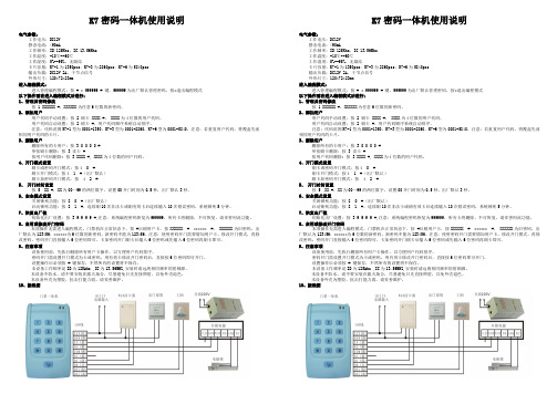
K7密码一体机使用说明电气参数:工作电压:DC12V静态电流:<90mA工作频率:ID 125Khz,IC 13.56Mhz工作温度:-10℃--60℃工作湿度:5%--95%,无凝结卡片容量:K7-1为1350pcs;K7-3为2860pcs;K7-6为5840pcs输出负载:DC12V 2A,干节点信号外形尺寸:120*72*23mm进入编程模式:进入管理编程模式:按 # * 999999 # 键,999999为出厂默认管理密码,按*退出编程模式以下操作需在进入编程模式后进行:1、管理员密码修改按 1 XXXXXX #,XXXXXX为任意6位数的新密码。
2、添加用户用户代码手动设置:按 2 刷卡 XXXX #。
XXXX为4位数的用户代码。
用户代码自动设置:按 2 刷卡 #,用户代码顺序系统自动排序。
注意:代码范围K7-1型为0001-1350,K7-3型为0001-2860,K7-6型为0001-5840,注意:若重复用户代码,将覆盖先前相同用户代码的卡片。
3、删除用户删除所有的卡用户:按 3 0 0 0 0 #单张刷卡删除:按 3 读卡 #按用户代码删除: 按 3 XXXX #, XXXX为4位数的用户代码。
4、开门模式设置刷卡或密码开门模式:按4 0 #刷卡开门模式:按4 1 #(出厂默认)刷卡加密码开门模式:按 4 2 #5、开门时间设置按 5 XX #,XX为00—99的两位数字,设置00开门时间为0.5秒,出厂默认3秒。
6、安全模式设置关闭锁死功能:按 8 0 #(出厂默认)启动锁死功能:按 8 1 #,连续刷10次非法卡或刷有效卡后连续输入10次错误密码,系统锁死5分钟。
7、恢复出厂值初始化出厂设置:按 3 9 9 9 9 #,注意:系统编程密码恢复为999999,所有卡将删除,不可恢复,请妥善用此功能。
8、启用或修改开门密码本项操作无需进入编程模式,门禁机在正常状态下,按 #后刷用户卡,按XXXXXX # ****** #, XXXXXX为旧密码,出厂默认为123456;******为6位数的新密码,新密码不能为123456。

61064 / 01 ArrayGuía de instalación y usuario3 4Instale el ensamble exteriorInstale el ensamble interior¿Cuál es el diámetro del orifi cio en la puerta?Retire la tapa interior y el paquete de baterías del ensamble interior.Conecte el cable más delgado.Conecte los cables correctamente y instale el ensamble interior.Conecte el cable más grueso.Instale el ensamble exterior y la placa de montaje.¿Cuál es el espesor de la puerta?AA BD C CBFEF2-1/8"54 mm1-1/2"38 mmoEl diámetro es 54 mm (2-1/8").El diámetro es 38 mm (1-1/2").Se requiere “F” para la instalación.Instale “F” en “E”.“F” no se necesita para la instalación.Descarta “F”.abcLMLNCompruebe que la perillaesté en la posición vertical.Retire la tapainterior.Retire elpaquete debaterías.Todavía no instalelas baterías.LPRECAUCIÓN: Manipulelos cables con cuidadopara evitar dañarlos. No tirede ellos ni utilice la fuerza.Asegúrese de que la conexiónsea firme.S (2x)a b cd eTuck cable hereInserte el cable aquíInsérez le câble iciExtienda el cable másgrueso contra elalojamiento interior.Presione el eje de la perilla en lapaleta de torsión.Evite pinzar el exceso de cabledelgado jalándolo lejos de la paletade torsión.Nota : La perilla de giro nopuede girar suavementehasta que después de laetapa 5.paleta detorsióneje de laperillaExtienda el cable más delgadoalrededor de la parte externa delconector cuadrado pertenecienteal cable más grueso.Pase el conector del cablemás delgado por detrás dela placa base (como seindica en la etiqueta delensamble interior).L Asegúrese de que la conexiónsea firme.EKKLQ/R (2x)GabcdeQ/RInserte la llave para probar el pestillo.Si el pestillo no se extiende o retrae consuavidad, ajuste los tornillos (Q/R).Retire la llave cuando haya terminado ycompruebe que el perno de retenciónesté extendido por completo.Los cables van pordebajo del pestillo.Encuentre la placa de montaje(K). Nota: La placa puede estarsituado en la parte posteriordel ensamble interior (L).Conecte loscables a travésdel orificiocentral y luegoempújelos por elorificio lateral.Mantenga paralelo alborde de la puertaAjuste los tornillosen forma uniformeorificiocentralorificiolateralQRoLa puerta es 35 mm (1-3/8")de espesor.La puerta es 44 mm (1-3/4")de espesor.Utilice los tornillos de plata más cortos.Utilice los tornillos de oro más largos.1-3/8"35 mm1-3/4"44 mmFunciones avanzadas©2014 Kwikset CorporationGuía de referenciaSensor de interior-exteriorLa cerradura Kevo cuenta con un sensor que le comunica si su dispositivo se encuentra dentro o fuera de su hogar para ayudar a prevenir que usuarios no autorizados abran la puerta mientras el dispositivo se encuentre en el interior.A partir de la versión de software 1.2.3., cada dispositivo de su sistema Kevo se calibrará automáticamente para habilitar este sensor. Para obtener más información sobre la calibración, consulte /kevo/support.Registro históricoPuede ver el historial de actividades de la cerradura a través de la aplicación Kevo o el portal web: .Notifi cacionesLa aplicación Kevo puede enviar notifi caciones cuando la puerta esté abierta y cerrada a través de los titulares de las llaveselectrónicas. Puede optar por recibir las notifi caciones predeterminadas del sistema o confi gurar las notifi caciones a medida paracontrolar a un usuario o período de tiempo determinado.Código de acceso de la aplicación KevoKevo presenta un código de acceso opcional para mayor seguridad que usted puede habilitar en el interior de la aplicación para usarlo encombinación con la contraseña de la aplicación. Para habilitar el código de acceso, debe ingresarlo cada vez que ingresa a la aplicación. Su función es proteger la cuenta Kevo de cambios no autorizados cuando su teléfono esté desbloqueado.Dispositivos compatibles con KevoTeléfonos inteligentes y dispositivos inteligentesUn teléfono inteligente (una tableta o un dispositivo móvile conectado a Internet) compatible con Kevo debe tener Bluetooth Smart Ready/ Bluetooth 4.0, y se debe instalar la aplicación Kevo específi ca del dispositivo. Averigüe si su dispositivo es compatible en /kevo/devices.Llavero transmisor KevoUn llavero transmisor es un dispositivo Bluetooth que proporciona la misma comodidad de tocar para abrir que un teléfono inteligente.Puede comprar llaveros transmisores adicionales según sea necesario. Puede registrar un máximo de ocho llaveros transmisores en una sola cerradura Kevo. Un solo llavero transmisor puede registrarse en 25 cerraduras Kevo.Nota: Puede elegir usar solamente llaveros transmisores Kevo,solamente dispositivos inteligentes o una combinación de ambos en su sistema Kevo.Llave estándarSiempre tenga acceso a la llave estándar de su cerradura.¿Necesita ayuda?1-800-327-56251-800-327-56251800 623 1180800 736 776/kevo/supportSi tiene preguntas, nuestro equipo de soporte Kevo altamente capac-itado pueden brindarle la ayuda que usted necesita:。

Dimensions are shown: mmSpecifications and dimensions subject to changeT a c t i l e S w i t c h esOrientation and Mounting Style SM Top Gullwing JM Top J Bend ****SAM Right angleSA1M Right angle with front solder padSA2M Right angle with front solder pad and pick & place tab SA3MRight angle with pick & place tabActuatorB0* Soft, flush B1* Soft, 0,64 mm B2* Soft, 2,24 mm P2** Hard, 2,36 mm P3** Hard, 1,12 mm P4** Hard, 3,96 mmS1*** ø0,1” for Press Fit Caps S2*** ø0,14” for Snap Fit Caps (with anti-rotation)3Features/Benefits• Full SMT side-actuated tact switch• SMT top-actuated tact switch with G or J terminations • High shear force with extended bracket • Easy to pick & place with top plate tab • Rubber or hard plastic actuator • Press fit or snap fit caps• RoHS compliant and compatibleTypical Applications • Telecommunications • Computer products • Instrumentation • Power supplySpecificationCONTACT ARRANGEMENT: SPST, N.O.TERMINALS: SMT terminationElectricalCONTACT RATING: 1.0 VA max. @ 32 V AC or DC max.ELECTRICAL & MECHANICAL LIFE: 100,000 make-and-break cycles at full load.DIELECTRIC STRENGTH: 250 Vrms min. @ sea level.CONTACT RESISTANCE: Below 50 mΩ typ. initial @ 2-4 V DC, 100 mA.INSULATION RESISTANCE: 109 Ω min.EnvironmentalOPERATING TEMPERATURES: A g version: -40˚C to 90˚CA u version: -40˚C to 125˚C ProcessSOLDERABILITY: Per MIL-STD-202F method 208D, or E IA RS-186E method 9 (1 hour steam aging).DEGREE OF PROTECTION: IP57; protection against harmful dust deposits, full-scale voltage protection.PackagingSwitches supplied in anti-static tape and reels per EIA 481-2. Tape and cover strip are conductive for use near statically sensitive components.NOTE : Specifications listed above are for switches with standard options.For information on specific and custom switches, consult Customer Service Center.BUTTONTo order buttons in bulk* B0, B1 & B2 available with A, A1 & A3 mounting bracket only.** P2, P3, P4 actuators suitable with A1 & A2 mounting bracket only.*** S1 & S2 available with A1 & A2 mounting bracket only.**** JM available with BO, B1, B2, P2, P3, P4 without mounting bracket.Button Color 90 Black80 Ivory (natural)40 RedSpecifications and dimensions subject to change3,18. * B0, B1 & B2 available with A, A1 & A3 mounting bracket only.** P2, P3, P4 actuators suitable with A1 & A2 mounting bracket only.*** S1 & S2 available with A1 & A2 mounting bracket only.**** JM available with BO, B1, B2, P2, P3, P4 without mounting bracket.Specifications and dimensions subject to changeT a c t i l e S w i t c h e sSpecifications and dimensions subject to changeTactile SwitchesSA3M RIGHT ANGLE WITH PICK & PLACE TAB(.125)3,18(.067)1,71(.114)2,904,61PAD LAYOUTSAM & SA3M MOUNTING BRACKETPAD LAYOUTSA1M & SA2M MOUNTING BRACKET24SCHEMATICDimensions are shown: mmSpecifications and dimensions subject to changeT a c t i l e S w i t c h esBUTTONTo order buttons in bulkMaterials: Nylon Finish: Gloss。

Ins-40077-US TOUCHLOCK K and KP series - ULMountingK75 Screw connector optionNOTE: The unit should be mounted in conjunction with an electrical backbox to achieve the required clearance for the connector .If an adaptor plate (310-750-US) is fitted, the mountings on the backbox can also be used.This keypad is designed to provide a Clock and Data output for Paxton (Net2 / Switch2).This unit is for Indoor use onlyNOTE: Illustrations in this instruction show the standard keypad.The KP series readers will also read Paxton tokens (Hitag2) and EM4100 tokens.Paxton03/14/2012Cable extensionsWiringNet2 control unitSwitch2 control unitStandard Unit - Drill a hole in the surface for the rear data cable. Secure the unit to the surface with three screws as per fitting diagram on page 1. 3 suitable screws and fixings are provided for fitting the unit to a wall. Ensure the data cable has free access at the rear .A choice of black and white covers are also provided. Hook the required cover over the top of the reader , press home at the bottom and secure with the single fixing screw.Screw Terminal Unit - The adapter (310-750-US) is mounted to a standard backbox using the fixing screws provided. The 75mm reader is then mounted onto the adapter using the fitting kit provided with the reader .KP series - When chosing a location for the reader , ensure that it is a least 12 inches from other readers. This will include readers mounted on the other side of the same wall as the radio signal will cause interference and reduce the read range. The reader should not be used on metal surfaces as the reflected signal will also reduce the range.Powering up the keypad will cause all the LEDs to come on. Once the control unit has been configured to accept keypad input (see controller instructions) pressing any key will make the keypad sound a bleep. Check the following FAQ section for assssistance if any problems are encountered.FCC ComplianceClass B digital devices.This equipment has been tested and found to comply with the limits for a Class B digital device, pursuant to Part 15 of theFCC Rules. These limits are designed to provide reasonable protection against harmful interference in a residential installation. This equipment generates, uses and can radiate radio frequency energy and, if not installed and used in accordance with the instructions, may cause harmful interference to radio communications. However , there is no guarantee that interference will not occur in a particular installation. If this equipment does cause harmful interference to radio or television reception, which can be determined by turning the equipment off and on, the user is encouraged to try to correct the interference by one or more of the following measures:-- Reorient or relocate the receiving antenna.-- Increase the separation between the equipment and receiver .-- Connect the equipment into an outlet on a circuit different from that to which the receiver is connected.-- Consult the dealer or an experienced radio/TV technician for help.Class A digital devices.This equipment has been tested and found to comply with the limits for a Class A digital device, pursuant to part 15 of the FCC Rules. These limits are designed to provide reasonable protection against harmful interference when the equipment is operated in a commercial environment. This equipment generates, uses, and can radiate radio energy and, if not installed and used in accordance with the instruction manual, may cause harmful interference to radio communications. Operation of this equipment in a residential area is likely to cause harmful interference in which case the user will be required to correct the interference at his own expense.This device complies with Part 15 of the FCC Rules. Operation is subject to the following two conditions:(1) this device may not cause harmful interference, and (2) this device must accept any interference received, including interference that may cause undesired operation. Changes or modifications not expressly approved by the party responsible for compliance could void the user's authority to operate the equipment.This unit is for Indoor use onlyFollowing the completed installation of this equipment, no further maintenance or testing is required.It is advisable to ensure that any third party backup power supplies or recovery procedures are checked regularly to ensure that the operation of the Paxton system is not compromised.Unit installation / test Maintenance/The use of any add-on, expansion, memory or other module manufactured or supplied by the manufacturer's representative will invalidate the CAN/ULC-S319 certification.For CAN/ULC-S319 installations, terminals, leads and wiring methods must comply with CSA, C22.1, Canadian electrical code, Part 1, safety standards for electrical installations.Product compliance and limitationsTo comply as a UL listed installation, the following conditions must apply:-Server based functions (Antipassback, Time and Attendance, etc) have not been evaluated by UL and cannot be used for UL 294 installations.The use of Wiegand readers and the configuration software has not been evaluated by 'UL' Wiring: - Where an equivalent cable / wire is used it must be ' UL Listed ' All interconnecting devices must be UL Listed.Wiring methods shall be in accordance with the National Electrical Code (ANSI/NFPA70), local codes, and the authorities having jurisdiction.This device complies with Industry Canada licence-exempt RSS standard(s). Operation is subject to the following two conditions: (1) this device may not cause interference, and (2) this device must accept any interference, including interference that may cause undesired operation of the device.。
第一章 K7型GPS测量系统简介 (3)1.1 系统的特色、组成、性能指标及配置 (3)1.1.1 K7型GPS新特色 (3)1.1.2系统组成 (3)1.1.3 K7测量系统的主要技术参数 (3)1.1.4 测量系统的基本配置 (4)1.2 K7型GPS测量系统的硬件 (5)1.2.1 K7型GPS接收机 (5)1.2.2 电池及充电器 (6)1.3 K7型GPS测量系统软件组成 (7)1.4 K7型GPS接收机充电及电源装卸 (7)一、打开K7主机侧面的电池后盖(见图1-2); (7)二、将电池后盖打开后取出锂电池(见图1-3),然后用配套充电器充电。
(7)第二章 K7型GPS测量系统实测 (8)2.1 概述 (8)2.2系统作业模式 (9)2.2.1 静态相对定位模式 (9)一、作业方法: (9)二、定位精度: (9)三、作业要求: (9)四、适用范围: (9)五、作业范围: (9)2.2.2后差分动态相对定位模式 (9)一、作业方法: (9)二、技术指标: (9)三、应用范围: (10)2.3 GPS网的技术设计 (10)2.3.1 测量的精度标准 (10)2.3.2网的图形设计 (11)2. 环形网 (11)3. 星形网 (12)2.3.3基线长度 (13)2.3.4网的基准 (13)2.4 选点与埋石 (13)2.4.1选点 (13)2.4.2 埋石 (14)2.5 K7型GPS测量系统的野外作业 (14)2.5.1 制定观测计划 (14)一、确定工作量 (14)二、采用分区观测 (15)三、选择观测时段 (15)四、确定观测进程及调度 (15)2.5.2安置及启动仪器 (16)2.5.3如何量取天线高即仪器高 (16)2.5.4启动仪器 (17)2.6 K7型接收机使用注意事项 (17)GPS测量应遵循《国家标准GPS测量规范》布网、施测、检核、计算。
(17)第三章K7型GPS测量系统文件及操作 (17)3.1 K7型文件系统简介与文件界面 (18)3.1.1 初始界面 (18)3.1.2 系统界面 (19)3.2 K7型文件系统野外数据采集 (23)3.2.1智能模式采集 (23)一、数据的采集: (23)二、给记录的数据取一个文件名: (24)三、退出数据记录: (25)3.2.2人工模式采集 (25)一、数据的采集: (25)二、给记录的数据取一个文件名: (25)三、退出数据记录: (25)3.2.3节电模式采集 (26)一、数据的采集: (26)第四章 K7内业数据传输 (27)4.1数据传输软件简介和界面 (27)4.1.1 菜单项 (27)四、查看菜单 (29)4.1.2 工具栏 (30)4.1.2 状态栏 (31)4.1.3 程序视窗 (31)4.2如何进行数据传输 (32)四、数据传输 (33)五、断开连接 (33)4.3.2检测注册码 (34)4.3.3设置功能 (35)第五章常见问题及解决方法 (35)第六章 K7后处理差分系统实测 (36)6.1.1 初始界面 (36)6.1.2 后差分野外作业步骤 (37)第七章如何升级主机软件 (39)附录A 有关专业术语注释 (41)附录B 年积日计算表 (43)附录C 联系方式 (45)附录D 全国销售及服务网络列表 (46)第一章 K7型GPS测量系统简介1.1 系统的特色、组成、性能指标及配置1.1.1 K7型GPS新特色K7智能一体化GPS接收机现已问世。
凯迪仕智能锁产品销售手册一、智能锁市场现状随着时代的发展,人们对生活品质的追求越来越高。
传统机械锁,结构简单,容易重码,安全性差。
且携带不便,使用烦琐。
近年来不断涌现的各种密码锁、磁卡锁、感应卡锁、指纹锁等智能锁具,已拥有相当规模的市场容量。
在安全、方便、智能等各方面有绝对优势的智能锁必将逐渐替代机械锁,这已是不可否认的事实。
来自资料搜索网() 海量资料下载目前国内的智能锁市场,经过多年的发展,已开始进入成长期。
去年国内已有过三百个新建房地产楼盘预装智能锁,智能锁已成为中高端楼盘必需卖点。
受此带动,民用零售市场也已启动,如深圳安防市场,超过30%的店铺有智能锁出售,各大建材市场,智能锁已是随处可见。
2009年智能锁中国市场总销量达五十亿,比上年增长130%。
但市场的普及率还是很低,相比国际发达国家,如韩国的智能锁普及率已在68%以上。
预计未来几年将是中国智能锁市场高速发展期,十年内市场容量必突破千亿大关。
在温州,市场上智能锁也已随处可见。
都市花苑新田园等楼盘已率先预装智能锁。
而去年市区开盘的十来个楼盘,大部分都准备安装智能锁,如绿城广场、香缇半岛、京都城等。
温州人消费意识超前,经济实力强,智能锁潜力巨大。
二、产品知识1、指纹锁指纹锁是一种以人体指纹为识别载体和手段的智能锁具,它是计算机信息技术、电子技术、机械技术和现代五金工艺的完美结晶。
指纹锁一般由电子识别与控制、机械联动系统两部分组成。
指纹的唯一性和不可复制性决定了指纹锁是目前所有锁具中最为安全的锁种。
2、关于半导体电容式指纹模块的介绍(1)从光学传感器到电容传感器——指纹采集技术的演进指纹传感器是实现指纹自动采集的关键器件。
最早的指纹识别技术,是以光学传感器为基础的光学识别系统,识别范围仅限于皮肤的表层,通常把它叫做第一代指纹识别技术;而采用了电容传感器技术的第二代指纹识别系统实现了识别范围从表皮到真皮的转换,从而大大提高了识别的准确率和系统的安全性。
#stage-page-metaproperties-ffe1fc1aa015e09df2fef3fbadb00c94#02012023KEMPPI K7 WELDING EQUIPMENTFastMig X IntelligentINTELLIGENT WELDING FOR THE DIVERSE NEEDS OFMULTI-MATERIAL WORKSHOPS2.01.2023FastMig X IntelligentHIGH-CLASS MULTI-PROCESS SOLUTION FORDIVERSE DEMANDING WELDING APPLICATIONSThe Wise software features built into the FastMig X Intelligent setup cover the diverse needs of the most demanding welding tasks. Typical applications include, for example,stainless steel process equipment, boats' and ships' hulls built out of aluminum,and power plant pressure vessels made under strict supervision and obligation to produce detailed quality documentation.The setup is flexible enough to adapt to fast-changing needs and capable enough to meet the ever increasing quality requirements.See intelligent welding at its finest. Learn more by visiting the KEMPPI FASTMIG X FAMILY SITE.KEY APPLICATIONSALUMINUM BOATS PRODUCTION LINES02012023FastMig X Intelligent3402012023BENEFITSFULL RANGE OF OPPORTUNITIES FOR INTELLIGENTWELDINGKemppi FastMig X setup for diverse welding is designed to give superior weldingquality and performance with limitless flexibility in specialized tasks andmaterials. Meeting the diverse needs of any metal fabrication workshop hasnever been this easy: look no further for the perfect MIG/MAG weldingequipment for a wide range of applications, from demanding manual welding toefficient mechanized welding.THE BEST SOLUTION OUT THEREWe have designed the perfect setup for specialized tasks in a variety of weldingconditions. Select from various optional features and modify the FastMig Xsystem to perform precise tasks according to your needs. Thanks to optimizedwelding properties for sheet metal and plates, all positions and materials, mixedgases and CO2the setup meets all productivity and quality requirements. Thissetup will always fulfill your ambitions in welding.MATCHING HIGH PRODUCT QUALITY WITH SUPERIORSERVICEFastMig X is fully compatible with the world's most comprehensive weldingmanagement software, WeldEye. Among other things, it monitors compliance tothe WPS, ensures that welders have appropriate qualifications, and collectsquality documentation.The Kemppi worldwide service network also ensuresimmediate support and consultation. Weld more, produce more, and profit morewith the FastMig X.WELD FASTER, REACH FURTHERMulti-process welding solutions are essential for multi-material workshops. Thissetup, specifically engineered to offer diverse welding options, includes anintelligent collection of device and software component choices. Weld even asmuch as 30 % faster, reach up to distances of 30 m, and benefit from 25%lower heat input. Choose FastMig X for high quality welding with an optimizedproduction flow.02012023FastMig X Intelligent5WHAT'S IN THE SETUP- EQUIPMENTFastMig X 450 Power source Provides 450 A with 60% duty cycle. Suitable forgenerator use.WFX 300 AMC Wire feederFor welding high-strength steels and aluminum with Ø 200/300 mm wire spools. Strong double-skin plastic casing with a reliable DuraTorque wire feed mechanism. Built-in arc voltage measurement.Compatible with the ARC Mobile Control app.Cool X Cooling unitCool X cooling unit for liquid-cooled setups is the ultimate choice providing 1 kW of cooling power with3 liters of cooling liquid.ARC Mobile ControlFor the first time in welding history, you can now control and monitor your welding machine wirelessly via a smartphone or tablet computer. Download theapp from Google Play.6FastMig X Intelligent02012023WHAT'S IN THE SETUP - SOFTWAREWiseFusionA welding function that ensures consistent weld quality in all positions by automatically regulating arc length. Creates and maintains an optimal short-circuit characteristic in pulsed MIG/MAG and spray-arc welding.WisePenetrationA welding function for ensured penetration in synergic MIG/MAG welding. Delivers constant power to the weld pool regardless of changes in welding gun orientation or distance between the welding gunand work piece.WiseThin+Optimized short arc process suitable for welding sheet metals and thicker plates in position welding,even in case of wider gaps and gap variations.Produces a spatterless arc with precise digitalcontrol.MatchLogMatchLog includes Minilog and MatchChannel activation in WFX feeders (Minilog can be used only with MXF feeders). MatchChannel allows changing of the memory channel during welding and Minilog enables to change welding power in the samememory channel.02012023FastMig X Intelligent 7ALTERNATIVE - EQUIPMENT AND SOFTWAREFastMig X 350 Power sourceProvides 350 A with 80% duty cycle. Suitable forgenerator use.FastMig X 350 MV Power sourceProvides 350 A with 80% duty cycle. Multi-voltage power source that connects to 220 V - 230 V and 380 V - 440 V (+/-10 V) 3-phase supply voltages.Suitable for generator use.WFX 200 AMC Wire feederFor welding high-strength steels and aluminum with Ø 200 mm wire spools. Strong double-skin plastic casing with a reliable DuraTorque wire feed mechanism. Built-in arc voltage measurement.Compatible with the ARC Mobile Control app.8FastMig X Intelligent 02012023FastMig X 450 Power sourceProduct code6103450Connection voltage 3~ 50/60 Hz400 V, (-15…+20%)Fuse (delayed)35AMinimum generator power35 kVAOutput 60% ED450 AOutput 100% ED350 AOpen circuit voltage MMA U0 = 70-98 VUav = 50 VOpen circuit voltage MIG/MAG U0 = 80 - 98 VOperating temperature range-20 ... +40 °CExternal dimensions LxWxH590 × 230 × 430 mmDegree of protection IP23SStandards IEC 60974-1, IEC 60974-5, IEC 60974-10WFX 300 AMC Wire feederProduct code6103533Output440 AOutput 60% ED520 AWire feed mechanism DuraTorqueGun connection EuroFiller wire sizes (Ss)0.6 - 1.6 mmFiller wire sizes (Al)0.8 - 2.4 mmFiller wire sizes (Fe)0.6 - 1.6 mmFiller wire sizes (Cored wire)0.8 - 2.0 mmWire feed speed 1 - 25 m/minSoftware WiseFusionWisePenetrationWiseThin+MatchLogSteel Pack (12 pcs)Steel Pack for Wise thin+ (8 pcs)Stainless Pack (12 pcs)Aluminum Pack (12 pcs)Operating temperature range-20 ... +40 °CExternal dimensions LxWxH625 × 243 × 476 mmDegree of protection IP23SStandards IEC 60974-5Wire spool weight, max.20 kgWeight (empty)12.5 kgWire spool diameter, max.300 mm02012023FastMig X Intelligent9Cool X Cooling unitProduct code6068200Cooling liquid - 10 liter can - SP9810765Operating voltage (safety voltage)400 V -15 …+20 %Maximum pressure0.4 MpaExternal dimensions LxWxH570 x 230 x 280 mmWeight (no accessories)11 kgDegree of protection IP23STank volume~3 LEMC class ACooling power 1 kWStorage temperature range-40 …+60 °COperating temperature-20 …+40 °C10FastMig X Intelligent02012023Kemppi is the design leader of the arc welding industry. We are committed to boosting the quality and productivity of welding by continuous development of the welding arc and by working for greener and more equal world. Kemppi supplies sustainable products, digital solutions, and services for professionals from industrial welding companies to single contractors. The usability and reliability of our products is our guiding principle. We operate with a highly skilled partner network covering over 70 countries to make its expertise locally available. Headquartered in Lahti, Finland, Kemppi employs close to 800 professionals in 16 countries and has a revenue of 178 MEUR.。
Specifications and dimensions subject to change Tactile SwitchesElectricalMAXIMUM POWE R: 0.5 VA MAXIMUM VOLTAGE: 32 VDC MINIMUM VOLTAGE: 20 mV MAXIMUM CURRENT DC: 50 mA MINIMUM CURRENT DC: 1 mA DIELECTRIC STRENGTH: ≥ 250 Vrms (1mn)CONTACT RESISTANCE: ≤ 150 mΩINSULATION RESISTANCE:≥ 50 MΩBOUNCE TIME: ≤ 6 msEnvironmentalOPERATING TEMPERATURE: -40˚C to 85˚CSTORAGE TEMPERATURE: -55˚C (10 days) +85˚C (4 days)ProcessSOLDERING: This component is suited to the following methods:– Lead free reflow soldering process in accordance with IEC61760-1.PackagingIn reels of 5,000 pieces.Dimensions of reels according to EIA 481BExternal diameter 180 mmNOTE: Specifications listed above are for switches with standard options.For information on specific and custom switches, consult Customer Service Center. Features• 3.0 x 2.6 mm footprint• Smallest thickness with integratedactuator• Extended life cycles• IP68• Ultra low current capabilitiesTypical Applications• M obile Phones•H earing Aids•M P3 accessories•B luetooth Headset•Automotive keyless entry system•S moke and CO detectors•E-readers•H ome automation remote controlsSpecificationFUNCTION: momentary action, normally openCONTACT ARRANGEMENT: 1 make contact = SPST, N.O.TERMINALS: J lead type for SMTMechanicalTRAVEL (mm): 0.15 ± 0.1Part Number DescriptionFor any part number different from those listed above, please consult your local representative.KMT0 SeriesNano-Miniature SMT Top ActuatedB–9Dimensions are shown: mm21 mar 18T a c t i l e S w i t c h e sKMT0 SeriesMinimum actuator diameter is 1.0 mm. It is recommended to enlarge this diameter to a full flat surface covering the switch.ø 1 mini 1,22,62,33,61,42,43( 0,05 )2,60,3H3,4±0,1RECOMMENDED LAYOUTELECTRICAL DIAGRAM10,06TAPE & REELA ABB2±0,051,75±0,1ø 1±0,13,2±0,10,25±0,12,8±0,05+0,312-0,14±0,050,75±0,15,5±0,05+0,1ø 1,5 03,6±0,11,4DE-REELING DIRECTIONOUT OF THE TAPE21 mar 18DesignationH ±0.07KMT011NGJLHS 0.63KMT021NGJLHS KMT031NGJLHS 0.65KMT071NGJLHS。
Programming and Troubleshooting GuideMastercode 2 Troubleshooting: Installation 10 Troubleshooting: Door Jamming and Door Handing 11 Troubleshooting: Touchscreen 14 Troubleshooting: Smart Home Systems 15 Troubleshooting: Battery 17 Battery FAQ 1862818 Rev 0213 24 5 6 7MastercodeUsing a Mastercode is an optional, added-security measure. It is not enabled by default. A Mastercode isused to add and delete user codes, but it cannot unlock the door (unless the same code is programmedas a user code, though this is not recommended). The Mastercode must be 4-8 digits.62818 Rev 02 1About the MastercodeIf programming is successful, the Checkmark will illuminate and you will hear one beep.If programming is unsuccessful, the “X” pattern will flash three times, and you will hear three beeps. Make sure the Mastercode has not already been programmed. Attempt the procedure again, making sure to enter the same new Mastercode in step 3 and 5.7. Make sure switch #3 is on, and press the Program button once. If youimmediately hear five beeps and see the Checkmark flash five times, the Mastercode is enabled.between 4 and 8 digits during your next attempt. Make sure the lock has room for an additional code. If all user codes are filled, delete a code to make room for this one. Make sure to enter a valid Mastercode in step 3.7. While the door is open and locked, test the user code to make sure it unlocks the door.10. While the door is open and locked, test the user code to makesure it no longer unlocks the door.next attempt.10. W hile the door is open and unlocked, press the Lock symbol. Ifthe latch bolt does not extend to lock, then all codes have been successfully deleted.you will hear three beeps. Make sure the Mastercode has been enabled before trying to disable it. Attempt the procedure again, making sure to enter the same Mastercode in step 4 and 6.8. Make sure switch #3 is on, and press the Program button once. If you don’t immediately hear five beeps and see the Checkmark flash five times, the Mastercode is disabled.Troubleshooting: InstallationIf you encounter any of the problems above, the deadbolt latch may be installed upside down. Remove the interior assembly, mounting plate, and exterior assembly from the door, and look at the latch inside the door hole.If the word “UP” is upside down and at the bottom of the latch, the latchReinstall the latch, making sure the word “UP” faces upward.62818 Rev 022The interior mounting screws are difficult to tighten.The interior and exterior assembly won’t mount parallel to the door edge.The interior assembly does not fit on the mounting plate.Troubleshooting: Door Jamming and Door Handing62818 Rev 02 3The lock jams and the turnpiece does not rotate smoothly.The clutch is disengaged.Remove the battery pack. Remove the interior assembly from the door. Verify that the lock can be operated smoothly with the key while the interior is removed. Attempt to rotate the turnpiece on the interior assembly to the vertical position. If it cannot rotate to the vertical position, the clutch has become disengaged.Place the battery cover onto the interior assembly, making sure to align the turnpiece with the shaft. Rotate the turnpiece 180° clockwise (you will need to use force when rotating the turnpiece, and you will hear itThe handing process may have been executed previously.Follow the instructions inside the Installation and User Guide to perform the manual door handing process The battery level is too low.This is indicated by the Checkmark and Lock symbols flashing simultaneously five times with five beeps. Use a fresh set of batteries, and perform the door handing process again.The hole in the door is misaligned. Disassemble the lock, and reinstall it without the adapter ring on the exterior side of the door.The mounting plate is placing tension on the torque blade.See page 12.The battery level is too low.This is indicated by the Checkmark and Lock symbols flashing simultaneously five times with five beeps. Use a fresh set of batteries, and perform the manual door handing process.The latch and strike are misaligned, causing the latch to bind.Perform the manual door handing process while the door is open. If itis successful only when the door is open, the latch and strike are not aligned as they should be. Ensure door preparation is in accordance with the door drilling instructions, available online.The door handing process does not happenautomatically when the batteries are installed.The touchscreen indicates a failure after the door handing process.The deadbolt latch does not extend or retract on its own during the door handing process.Troubleshooting: TouchscreenScreen activationTo activate the screen, use one of the three options below:1. Touch screen with palm or back of hand until digits illuminate.2. Touch lower left area of screen (where Checkmark is located) untildigits illuminate.3. Touch screen with three or more fingers until digits illuminate.One-second pauseThe lock requires a one-second pause immediately after locking or unlocking before the touchscreen will re-activate. Fully remove hand from screen until the Checkmark or Lock symbol turns off, and then activate the screen again.Touchscreen lockoutIf three incorrect codes were entered within one minute, the touchscreen will lock for 60 seconds.No user codes are programmed.If there are no codes in the lock, the lock symbol will not lock the door. This is indicated by the “X” pattern flashing three times with three beeps. Program at least one user code and test the Lock symbol again.The door handing process was not executed. Perform the manual door handing process, following the instructions inside the Installation and User guide.The battery is too low to lock the door.This is indicated by the Checkmark and Lock symbols flashing simultaneously five times with five beeps. Remove the batteries and replace with a fresh set.The mounting plate is placing tension on the torque blade.See page 12.The clutch is disengaged.See page 12.SecureScreen is enabled.SecureScreen is an added-security feature that displays random digits before you enter a user code to unlock the door. This feature ensures that there are fingerprints on all digits so that codes cannot be identified by examining the touchscreen for fingerprints.If desired, this feature can be disabled by turning switch #4 to the off position.62818 Rev 024The touchscreen is unresponsive.The Lock symbol does not lock the door. Only two digits illuminate on the touchscreen.Troubleshooting: Smart Home SystemsThe lock was not removed completely from another network before being paired with the new network.Follow your smart home system’s instructions to remove (exclude/unpair) the device from any other network. Then, attempt to pair (add/include) the lock again.The lock is not close enough to the controller.Some Z-wave systems require that the lock be within 12" of the controller during the pairing (inclusion/adding) process. If this is the case, remove the lock from the door to perform the pairing process closer to the controller.IMPORTANT: The lock has an anti-tamper alarm that will sound if the interior is disconnect from the exterior while the batteries are installed. Follow steps in order:a. Remove the battery pack from the interior assembly.b. Remove interior assembly from the mounting plate.c. Remove the exterior assembly from the door.d. Connect the cable from the exterior assembly to the interior assembly.e. Reinstall the battery pack.f. Perform the inclusion process while the interior and exterior are connected.62818 Rev 025The lock fails to pair with a Z-wave smart home system.The system needs a repeater or router to reach the lock.Adding repeaters to your system may help communication between your lock and the controller, especially if they are far away from each other.The network configuration changed.If any repeaters or routers in the system were moved since adding the lock to the system, perform the “rediscover” process in your system’s user interface.The lock is in sleep mode.If the lock has been unable to communicate with the system after multiple attempts, it will go into sleep mode. Lock and unlock the doorwith a key so that the lock status transmits to the system. If it still does not communicate, remove (exclude/unpair) the lock from your system. Then, pair (add/include) the lock with your system again. If the problem persists, add a repeater or router between the controller and lock if none presently exist in the system.The light module or switch is not beaming capable.Z-Wave locks: Ensure the light module or switch located between the controller and lock is beaming capable.ZigBee locks: Ensure the router is reachable by both controller and lock.62818 Rev 02I can see the lock in my controller, but I can’t control it from the controller.1. Reboot the lock:a. Remove the battery pack from the lock.b. Press the "Program" button for 5 seconds and then the "A" button for 5 seconds.c. If TS (touchscreen controller) shows low battery trouble for the lock subjected to the firmware update then install new batteries in pack.d. Replace the battery pack into the lock.e.If lock still fails to OTA update firmware, proceed to Step 2.2. Delete, default, and pair lock again:a. Delete the lock from TS (touchscreen controller).b.Perform a factory reset:i. Remove the battery pack from the lock.ii.Press the "Program" button for 5 seconds and then the "A" button for 5 seconds.iii. Press and hold the "Program" button whilereinserting the battery pack. Keep holding the button for 30 seconds until the lock beeps and the status LED flashes red.iv. Press the "Program" button momentarily.v. After several seconds, the lock will flash the statusLED red and green several times and beeps twice (if audio is enabled) to indicate factory reset is complete.c. For model 910 or 914, perform handing on the lock. For model 916, it will automatically perform handing.d. Pair the lock with TS again.e.If lock still fails to OTA update firmware, proceed to Step 3.3. If lock still fails to OTA update firmware after going through steps1 and 2, it is recommended that your MSO/service provider contactKwikset/Weiser for advanced replacement of the lock.The lock fails to update or pair with a service provider's ZigBee smarthome system.Lock fails to OTA (Over the Air) update firmware.Troubleshooting: BatteryThe lock must be replaced. Contact Technical Support.The Wireless Card LEDs are staying on.Remove the battery pack, press and hold the program button for 10 seconds. Replace the battery pack. If the Wireless Card LEDs continue to stay on, contact Technical Support.The smart home system’s user interface falsely reports a low battery.If you receive an alert from your smart home system indicating that the battery is low, confirm this is true at the lock. Turn on switch #1 so that the status LED flashes every six seconds. If the LEDs turn amber or green, followed by a red flash, the battery is low. If the red flash is not seen, the battery is not low. This is an error on the smart home system side that will often be fixed when the lock is manually locked orunlocked.The smart home system controller’scommunication with the lock is draining the battery.Remove the lock from your system. Put a new set of batteries in the lock. Operate the lock in stand-alone mode for a week. If the batteries drain within the week, the problem resides in the lock. If the batteries do not drain, the problem may be the smart home controller. Call Technical Support.The smart home system controller’s ping frequency is too high.Decrease the ping frequency from the controller to the lock to the lowest possible setting.To ensure proper operations post power cycle, allow 30 secondsbetween battery removal and replacement. If the lock still displays low battery behavior and/or fails to join/rejoin a ZigBee network, remove the battery pack, press and hold the program button for 5 seconds thenpress and hold button A for 5 seconds. Replace the battery pack.The lock still shows low battery behavior locally and/or on SmartHome consoleafter fresh batteries were installed:62818 Rev 026The batteries drain within one day.The batteries drain within one week.The batteries drain within a few weeks.Battery FAQHow long will the lock operate on a set of batteries?Based on 10 operations per day, a single, new set of Alkaline batteries will operate the lock for over a year.What type of batteries do you recommend? For best results, use new non-rechargeable Alkaline batteries only.I am planning to be away for several months. Will my lock operate when I get back?When the system is idling, it consumes minimum power (very close to battery shelf life.) With alkaline batteries, the lock should be operable after years of idle. I replaced my batteries less than a year agoand need to replace them again.Check your door alignment. If the deadbolt makes several unsuccessful attempts to lock or unlock the door, it may mean that the door is warpedand the latch does not line up correctly with the strike. Operating thelock excessively reduces battery life. Avoid turning on the keypad light unnecessarily.What settings should I use to get themaximum battery life out of my lock?Set all switches to the OFF position.62818 Rev 027。
1德國凱馳家用高壓清洗機K 5 中文說明書(一) 主機本體與配件名稱1. 快速接頭轉接環2. 高壓管快速接口3. 進水口(含過濾裝置)4. 電源開關ON/OFF5. 大型手提把6. 配件收納網7. 配件收納處8. 主機電源線9.清潔劑吸管附過濾嘴10. 大型滾輪與輪栓 11. 高壓槍把12. 高壓槍把安全鎖 13. 高壓管移除鎖 14. 高壓管 15. 螺旋噴桿16. 高低壓可調噴桿17. 自購水管,主機使用一般/棉質4分水管18.高壓槍把固定架(二) 安全提示使用本產品前,請遵守下列基本安全事項 - 第一次使用前,請務必詳閱本說明書。
- 請了解主機安裝、操作高壓與關閉主機方式。
- 請勿於身體不適時操作主機,以免發生危險。
- 請遵守本說明之配件使用、保養與維修資訊。
(三) 使用前 組件安裝步驟A 、安裝主機滾輪步驟B 、將主機手提把安裝於主機上,槍把固定架安裝於主機側邊步驟C 、安裝配件收納網,將收納網分別掛於兩側勾環內安裝快速進水接頭步驟D 、將高壓管插入噴槍內直到聽到「喀」 的聲音。
安裝後輕拉高壓管確認安裝妥當。
拆除高壓管與噴槍連接:按下高壓管移除鎖將高壓管移除。
步驟E/F 、將高壓管另一端直接插入主機高壓管快速接頭內並聽到「喀」確認已經固定。
移除高壓管時請將高壓快速接頭往外按壓拔除高壓管即可。
2步驟G 、安裝前請確實將槍把安全鎖鎖上。
安裝噴桿,請依照槍桿孔型將噴桿按壓入槍把孔內後逆時針方向鎖緊。
注意:請確認槍桿已確實固定於槍把上,以免造成危險。
步驟H 、使用清潔劑自吸功能。
請先行安裝高低壓可調式噴桿後。
將清潔劑吸管從主機後下方輕拉出,插入清潔劑中。
使用時請將高低壓噴桿調置低壓設定方能進行自吸清潔劑,清潔劑自吸需啟動槍把後1-2分鐘出清潔劑才會噴射出。
注意:請勿使用粉狀或過於濃稠清潔劑(沙拉脫)步驟I 、將大型手提把拉出移動,請確實拉出後聽到「喀」聲音表示固定。
收回時請往下按壓把手縮回把手。