电磁铁-EPM501B说明书2013(中性)
- 格式:pdf
- 大小:57.73 KB
- 文档页数:7

第1篇一、前言电磁兼容(Electromagnetic Compatibility,简称EMC)是指电子产品在正常使用过程中,自身产生的电磁干扰(EMI)不会对其他电子设备造成干扰,同时自身也能够抵抗外界电磁干扰的能力。
随着电子产品的广泛应用,电磁兼容问题日益突出,因此,了解电磁兼容产品及其使用方法至关重要。
本说明书旨在为您提供电磁兼容产品的相关指南。
二、电磁兼容产品概述1. 电磁兼容产品定义电磁兼容产品是指符合电磁兼容性要求,能够在电磁环境中正常运行,不对其他设备产生干扰,同时也能抵抗外界电磁干扰的电子产品。
2. 电磁兼容产品类型(1)滤波器:用于抑制电磁干扰,提高电磁兼容性。
(2)屏蔽材料:用于屏蔽电磁干扰,保护设备免受干扰。
(3)接地材料:用于将设备中的干扰电流引入大地,降低干扰。
(4)电源线滤波器:用于降低电源线中的电磁干扰。
(5)电源线接地线:用于将设备中的干扰电流引入大地。
三、电磁兼容产品选购指南1. 了解产品性能参数在选购电磁兼容产品时,首先要了解产品的性能参数,如滤波器的插入损耗、屏蔽材料的屏蔽效能、接地材料的接地电阻等。
这些参数将直接影响产品的电磁兼容性能。
2. 选择正规厂家生产的产品选购电磁兼容产品时,应选择正规厂家生产的产品,确保产品质量。
正规厂家生产的电磁兼容产品通常具有较高的性能和可靠性。
3. 检查产品认证证书在选购电磁兼容产品时,要检查产品是否有相应的认证证书,如CE认证、RoHS认证等。
这些证书表明产品符合国际标准,具有较高的质量。
4. 注意产品包装和标识选购电磁兼容产品时,要注意产品的包装和标识。
正规厂家生产的产品包装完整,标识清晰,便于识别。
四、电磁兼容产品使用指南1. 滤波器使用指南(1)正确连接滤波器:将滤波器按照产品说明书要求正确连接到电路中。
(2)选择合适的滤波器:根据电路中的干扰频率和功率,选择合适的滤波器。
(3)注意滤波器安装位置:滤波器应安装在干扰源附近,以便有效抑制干扰。
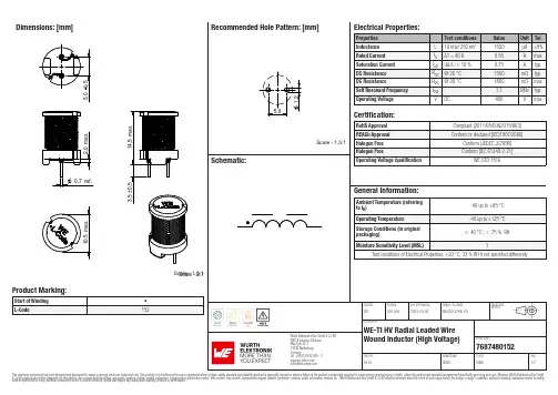
Dimensions: [mm]Scale - 2:1Scale - 1,5:176********768748015276874801527687480152T e m p e r a t u r eT T T 7687480152Cautions and Warnings:The following conditions apply to all goods within the product series of WE-TI-HV ofWürth Elektronik eiSos GmbH & Co. KG:General:•This electronic component is designed and manufactured for use in general electronic equipment.•Würth Elektronik must be asked for written approval (following the PPAP procedure) before incorporating the components into any equipment in fields such as military, aerospace, aviation, nuclear control, submarine, transportation (automotive control, train control, ship control), transportation signal, disaster prevention, medical, public information network, etc. where higher safety and reliability are especially required and/or if there is the possibility of direct damage or human injury.•Electronic components that will be used in safety-critical or high-reliability applications, should be pre-evaluated by the customer. •The component is designed and manufactured to be used within the datasheet specified values. If the usage and operation conditions specified in the datasheet are not met, the wire insulation may be damaged or dissolved.•Do not drop or impact the components, the component may be damaged.•Würth Elektronik products are qualified according to international standards, which are listed in each product reliability report. Würth Elektronik does not warrant any customer qualified product characteristics beyond Würth Elektroniks’ specifications, for its validity and sustainability over time.•The responsibility for the applicability of the customer specific products and use in a particular customer design is always within the authority of the customer. All technical specifications for standard products also apply to customer specific products.Product specific:Soldering:•The solder profile must comply with the technical product specifications. All other profiles will void the warranty.•All other soldering methods are at the customers’ own risk.Cleaning and Washing:•Washing agents used during the production to clean the customer application might damage or change the characteristics of the wire insulation, marking or plating. Washing agents may have a negative effect on the long-term functionality of the product. Potting:•If the product is potted in the customer application, the potting material might shrink or expand during and after hardening. Shrinking could lead to an incomplete seal, allowing contaminants into the core. Expansion could damage the component. We recommend a manual inspection after potting to avoid these effects.Storage Conditions:• A storage of Würth Elektronik products for longer than 12 months is not recommended. Within other effects, the terminals may suffer degradation, resulting in bad solderability. Therefore, all products shall be used within the period of 12 months based on the day of shipment.•Do not expose the components to direct sunlight.•The storage conditions in the original packaging are defined according to DIN EN 61760-2.•The storage conditions stated in the original packaging apply to the storage time and not to the transportation time of the components. Packaging:•The packaging specifications apply only to purchase orders comprising whole packaging units. If the ordered quantity exceeds or is lower than the specified packaging unit, packaging in accordance with the packaging specifications cannot be ensured. Handling:•Violation of the technical product specifications such as exceeding the nominal rated current will void the warranty.•Applying currents with audio-frequency signals may result in audible noise due to the magnetostrictive material properties.•Due to heavy weight of the components, strong forces and high accelerations may have the effect to damage the electrical connection or to harm the circuit board and will void the warranty.•Please be aware that products provided in bulk packaging may get bent and might lead to derivations from the mechanical manufacturing tolerances mentioned in our datasheet, which is not considered to be a material defect.•The temperature rise of the component must be taken into consideration. The operating temperature is comprised of ambient temperature and temperature rise of the component.The operating temperature of the component shall not exceed the maximum temperature specified.These cautions and warnings comply with the state of the scientific and technical knowledge and are believed to be accurate and reliable.However, no responsibility is assumed for inaccuracies or incompleteness.Würth Elektronik eiSos GmbH & Co. KGEMC & Inductive SolutionsMax-Eyth-Str. 174638 WaldenburgGermanyCHECKED REVISION DATE (YYYY-MM-DD)GENERAL TOLERANCE PROJECTIONMETHODTRi001.0002021-03-02DIN ISO 2768-1mDESCRIPTIONWE-TI HV Radial Leaded WireWound Inductor (High Voltage)ORDER CODE7687480152SIZE/TYPE BUSINESS UNIT STATUS PAGEImportant NotesThe following conditions apply to all goods within the product range of Würth Elektronik eiSos GmbH & Co. KG:1. General Customer ResponsibilitySome goods within the product range of Würth Elektronik eiSos GmbH & Co. KG contain statements regarding general suitability for certain application areas. These statements about suitability are based on our knowledge and experience of typical requirements concerning the areas, serve as general guidance and cannot be estimated as binding statements about the suitability for a customer application. The responsibility for the applicability and use in a particular customer design is always solely within the authority of the customer. Due to this fact it is up to the customer to evaluate, where appropriate to investigate and decide whether the device with the specific product characteristics described in the product specification is valid and suitable for the respective customer application or not.2. Customer Responsibility related to Specific, in particular Safety-Relevant ApplicationsIt has to be clearly pointed out that the possibility of a malfunction of electronic components or failure before the end of the usual lifetime cannot be completely eliminated in the current state of the art, even if the products are operated within the range of the specifications.In certain customer applications requiring a very high level of safety and especially in customer applications in which the malfunction or failure of an electronic component could endanger human life or health it must be ensured by most advanced technological aid of suitable design of the customer application that no injury or damage is caused to third parties in the event of malfunction or failure of an electronic component. Therefore, customer is cautioned to verify that data sheets are current before placing orders. The current data sheets can be downloaded at .3. Best Care and AttentionAny product-specific notes, cautions and warnings must be strictly observed. Any disregard will result in the loss of warranty.4. Customer Support for Product SpecificationsSome products within the product range may contain substances which are subject to restrictions in certain jurisdictions in order to serve specific technical requirements. Necessary information is available on request. In this case the field sales engineer or the internal sales person in charge should be contacted who will be happy to support in this matter.5. Product R&DDue to constant product improvement product specifications may change from time to time. As a standard reporting procedure of the Product Change Notification (PCN) according to the JEDEC-Standard inform about minor and major changes. In case of further queries regarding the PCN, the field sales engineer or the internal sales person in charge should be contacted. The basic responsibility of the customer as per Section 1 and 2 remains unaffected.6. Product Life CycleDue to technical progress and economical evaluation we also reserve the right to discontinue production and delivery of products. As a standard reporting procedure of the Product Termination Notification (PTN) according to the JEDEC-Standard we will inform at an early stage about inevitable product discontinuance. According to this we cannot guarantee that all products within our product range will always be available. Therefore it needs to be verified with the field sales engineer or the internal sales person in charge about the current product availability expectancy before or when the product for application design-in disposal is considered. The approach named above does not apply in the case of individual agreements deviating from the foregoing for customer-specific products.7. Property RightsAll the rights for contractual products produced by Würth Elektronik eiSos GmbH & Co. KG on the basis of ideas, development contracts as well as models or templates that are subject to copyright, patent or commercial protection supplied to the customer will remain with Würth Elektronik eiSos GmbH & Co. KG. Würth Elektronik eiSos GmbH & Co. KG does not warrant or represent that any license, either expressed or implied, is granted under any patent right, copyright, mask work right, or other intellectual property right relating to any combination, application, or process in which Würth Elektronik eiSos GmbH & Co. KG components or services are used.8. General Terms and ConditionsUnless otherwise agreed in individual contracts, all orders are subject to the current version of the “General Terms and Conditions of Würth Elektronik eiSos Group”, last version available at .Würth Elektronik eiSos GmbH & Co. KGEMC & Inductive SolutionsMax-Eyth-Str. 174638 WaldenburgGermanyCHECKED REVISION DATE (YYYY-MM-DD)GENERAL TOLERANCE PROJECTIONMETHODTRi001.0002021-03-02DIN ISO 2768-1mDESCRIPTIONWE-TI HV Radial Leaded WireWound Inductor (High Voltage)ORDER CODE7687480152SIZE/TYPE BUSINESS UNIT STATUS PAGE。
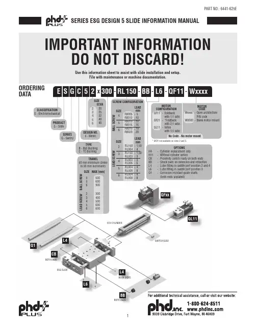
No Code -No motor mountRL 300x -WxxxxQF 511150--SIZE 20253250 mm minimum stroke in 50 mm increments TRAVEL DESIGN NO.5 - MetricSCREW CONFIGURA B A L L S C R E WTIONSIZE 456mm------L E A D S C R E WB A L L SC R E WL E A D S C R E WSIZE 234LEADLEAD mm1.5041.50336RL150 -RL004 -RL150 -RL003 -RL003 -RL006 -564848RL004 -RL008 -RL004 -RL008 -E S PRODUCT S - SlideSERIES G - GantryCLASSIFICATION E - ElectromechanicalG C 2BB TYPE B - Ball Bushing C - TC Bushing 234404056MAX [mm]500600600SIZE 44003300500600900256456-L6-MOTOR CONFIGURATION QF11-Foldbackwith 1:1 ratioQF21-*Foldbackwith 2:1 ratioQL11-Inlinewith 1:1 ratioMOTOR CODEWxxxx -Open architectureP/N codeW0000-Blank motor mountECVA * QF21 not available on sizes 2 and 3.RB005 RB010 RB010 RB016 RB010 RB020 51010161020OPTIONS H4-Cylinder replacement only H11-Without cylinder option CB -Proximity switch ready on both ends BB -Shock pads on extension and retraction L4-Lube fitting in saddle port position 2 and 4L6-Lube fitting in saddle port position 3Q1-Corrosion resistant guide shafts (both ends unplated)BOTH ENDSBOTH ENDSBBQFxxQL11Q1CBL6BOTH SIDESL4L4ORDERING DATAUse this information sheet to assist with slide installation and setup. File with maintenance or machine documentation.IMPORTANT INFORMATIONDO NOT DISCARD!SERIES ESG DESIGN 5 SLIDE INFORMATION MANUALSPECIFICATIONSBALL SCREW SERIES ESG REPEATABILITY1±0.010 mm [±0.0004 in]MAXIMUM BACKLASH 20.18 mm [0.007 in]RATED LIFERefer to Life vs. Thrust Chart FULL TRAVEL TOLERANCE 7+3.5/-0.0 mm [+0.138/-0.000 in]DUTY CYCLE100%OPERATING TEMPERATURE 4 - 65°C [40 - 150°F]LUBRICATION INTERVAL 3Horizontal: 2500 km [100 million in], Vertical: 1500 km [60 million in]SPECIFICATIONSSIZE 456M E C H A N I C SMAXIMUM TRAVELmm [in]500 [19.69]600 [23.62]900 [35.43]DRIVE MECHANISM Ball ScrewSCREW DIAMETERmm 121616SCREW CONFIGURATION -RB005-RB010-RB010-RB016-RB010-RB016SCREW LEADmm/rev 51010161016GUIDE SHAFT DIAMETER mm162025GUIDE SHAFT BEARING TYPE Ball BushingS P E E D 4MAXIMUM SPEED mm/sec [in/sec]500 [19.6]1000 [39.3]1000 [39.3]1600 [63.0]1000 [39.3]1600 [63.0]MAXIMUM RPMrev/min 6000MAXIMUMACCELERATION -QL11mm/sec 2[in/sec 2]19.6 [772]-QFx1mm/sec 2 [in/sec 2]9.8 [386]T H R U S T 4MAXIMUM THRUST N [lbf]1360 [306]680 [153]2430 [546]1520 [342]2430 [546]1520 [342]NOMINAL THRUST 5N [lbf]400 [90]330 [74]1270 [285]975 [219]1270 [285]975 [219]T O R Q U E PERMISSIBLE DRIVE TORQUE 6-QL11Nm [in-lb] 1.2 [10.62] 4.3 [38.06] 4.3 [38.06]-QFx1Nm [in-lb]0.84 [7.43] 3 [26.55] 3 [26.55]NO-LOAD TORQUENm [in-lb]0.15 [1.33]0.40 [3.54]0.60 [5.31]W E I G H TTOTAL @ ZERO STROKE (W OT )kg [lb] 6.21 [13.7]8.56 [18.87]11.19 [24.67]TOTAL LENGTH ADDER (W LT )kg/mm [lb/in]0.010 [0.57]0.132 [0.74]0.0169 [0.92]MOVING @ ZERO STROKE (W OM )kg [lb] 2.45 [5.41] 3.84 [8.47] 4.89 [10.67]MOVING LENGTH ADDER (W LM )kg/mm [lb/in]0.0006 [0.038]0.0010 [0.058]0.0010 [0.058]I N E R T I AACTUATOR @ ZERO STROKE (J O )kg-m 2 [lb-in 2] 3.00 x 10⁻⁶[0.010] 1.50 x 10⁻⁵ [0.051] 1.50 x 10⁻⁵ [0.051]LENGTH ADDER (J L )kg-m 2/mm [lb-in 2/in]9.85 x 10-9 [0.0009] 2.90 x 10⁻⁸ [0.0025]2.90 x 10⁻⁸ [0.0025]MOVING WEIGHT ADDER (J M )kg-m 2/kg [lb-in 2/lb] 6.21 x 10-72.48 x 10-6 2.48 x 10⁻⁶ 6.36 x 10⁻⁶ 2.48 x 10⁻⁶ 6.36 x 10⁻⁶[9.63 x 10⁻⁴][3.85 x 10⁻³][3.85 x 10⁻³][9.86 x 10⁻³][3.85 x 10⁻³][9.86 x 10⁻³]MOTORCONFIGURATION (J Q )-QF11kg-m 2 [lb-in 2] 1.40 x 10⁻⁵ [0.048] 4.71 x 10⁻⁵ [0.161]4.71 x 10⁻⁵ [0.161]-QF21 2.75 x 10⁻⁵ [0.094]8.28 x 10⁻⁵ [0.283]8.28 x 10⁻⁵ [0.283]-QL113.14 x 10-6 [0.011] 6.11 x 10⁻⁶ [0.021]6.11 x 10⁻⁶ [0.021]NOTES:1) UNIDIRECTIONAL2) AXIAL FREE PLAY WHEN DRIVE SHAFT LOCKED3) REFER TO OPERATING INSTRUCTIONS FOR RE-LUBRICATION DETAILS 4) REFER TO PERFORMANCE CHARTS IN CATALOG 5) 2500 km [100 MILLION in] LIFE6) CORRESPONDS TO MAXIMUM THRUST7) FOR HOMING AND INCREASED APPLICATION FLEXIBILITY, INCLUDE EXTRA TRAVEL WHEN NECESSARY 8) ALL DIMENSIONS ARE FOR REFERENCE ONLY UNLESS SPECIFICALLY TOLERANCED. REFER TO ONLINE SIZING SOFTWARE FOR ACTUAL VALUES.SPECIFICATIONSLEAD SCREW SERIES ESG REPEATABILITY 1±0.5 mm [±0.020 in] (Typical)MAXIMUM BACKLASH 20.20 mm [0.008 in]RATED LIFERefer to Online SizingFULL TRAVEL TOLERANCE +3.5/-0.0 mm [+0.138/-0.000 in]MAXIMUM DUTY CYCLE 35%OPERATING TEMPERATURE 4 - 65°C [40 - 150°F]LUBRICATION INTERVAL 3Horizontal: 500 km [20 million in], Vertical: 250 km [10 million in]SPECIFICATIONSSIZE23456M E C H A N I C SMAXIMUM TRAVEL mm [in]300 [11.811]400 [15.70]500 [19.69]600 [23.62]600 [23.62]SCREW DIAMETER mm810121616SCREW CONFIGURATION -RL150-RL004-RL150-RL003-RL003-RL006-RL004-RL008-RL004-RL008SCREW LEADmm/rev 1.541.53364848GUIDE SHAFT DIAMETER mm10 [0.394]12 [0.472]16 [0.630]20 [0.787]25 [0.984]GUIDE SHAFT BEARING TYPE Composite Bushing S P E E D 4MAXIMUM SPEED mm/sec [in/sec]30 [1.2]80 [3.15]30 [1.20]60 [2.40]60 [2.40]120 [4.80]80 [3.15]160 [6.30]80 [3.15]160 [6.30]MAXIMUM RPMrev/min1200MAXIMUM ACCELERATION m/sec 2[in/sec 2]0.3 [11.81]1.0 [39.37]0.3 [11.81] 1.0 [39.37]0.3 [11.81] 1.0 [39.37]0.5 [19.69] 1.0 [39.37]0.5 [19.69] 1.0 [39.37]T H R U S T 4MAXIMUM THRUST N [lbf]300 [67.5]150 [33.7]500 [112]250 [56]800 [180]400 [90]1600 [360]800 [180]1600 [360]800 [180]T O R Q U EPERMISSIBLE DRIVE TORQUE 5-QL11Nm [in-lb]0.5 [4.42]0.7 [6.20] 1.2 [10.62] 4.3 [38.06] 4.3 [38.06]-QFx1Nm [in-lb]0.84 [7.43] 3 [26.55] 3 [26.55]NO-LOAD TORQUENm [in-lb]0.09 [0.80]0.12 [1.00]0.15 [1.33]0.40 [3.54]0.60 [5.31]W E I G H TTOTAL @ ZERO STROKE (W OT )kg [lb] 2.57 [5.66] 3.37 [7.42] 6.13 [13.54]8.45 [18.63]11.08 [24.43]TOTAL LENGTH ADDER (W LT )kg/mm [lb/in]0.003 [0.14]0.004 [0.21]0.010 [0.57]0.0132 [0.74]0.017 [0.92]MOVING @ ZERO STROKE (W OM )kg [lb] 1.07 [2.35] 1.50 [3.31] 2.38 [5.25] 3.73 [8.23] 4.735 [10.43]MOVING LENGTH ADDER (W LM )kg/mm [lb/in]0.0004 [0.021]0.0007 [0.038]0.0007 [0.038]0.0010 [0.058]0.0010 [0.058]I N E R T I AACTUATOR @ ZERO STROKE (J O )kg-m 2[lb-in 2]1.66 x 10⁻⁶[0.006]2.09 x 10⁻⁶[0.007]3.00 x 10⁻⁶[0.010]1.50 x 10⁻⁵[0.051]1.50 x 10⁻⁵ [0.051]LENGTH ADDER (J L ) kg-m 2/mm [lb-in 2/in] 1.59 x 10⁻⁹ [0.00014]4.94 x 10⁻⁹ [0.00043]9.85 x 10⁻⁹ [0.0009] 2.90 x 10⁻⁸ [0.0025] 2.90 x 10⁻⁸ [0.0025]MOVING WEIGHT ADDER (J M )kg-m 2/kg [lb-in 2/lb] 3.8 x 10-81.01 x 10-7 3.8 x 10-87.6 x 10-87.6 x 10⁻⁸ 1.52 x 10⁻⁷ 1.01 x 10-72.03 x 10-7 1.01 x 10⁻⁷ 2.03 x 10⁻⁷[5.89 x 10⁻⁵][1.57 x 10⁻⁴][5.89 x 10⁻⁵][1.18 x 10⁻⁴][1.18 x 10⁻⁴][2.36 x 10⁻⁴][1.57 x 10⁻⁴][3.14 x 10⁻⁴][1.57 x 10⁻⁴][3.14 x 10⁻⁴]MOTORCONFIGURATION (J Q )-QF11kg-m 2 [lb-in 2]2.69 x 10⁻⁵ [0.092] 2.69 x 10⁻⁵ [0.092] 1.40 x 10⁻⁵ [0.048] 4.71 x 10⁻⁵ [0.161] 4.71 x 10⁻⁵ [0.161]-QF21––2.75 x 10⁻⁵ [0.094]8.28 x 10⁻⁵ [0.283]8.28 x 10⁻⁵ [0.283]-QL111.89 x 10-6 [0.006]1.89 x 10⁻⁶ [0.006]3.14 x 10⁻⁶ [0.011]6.11 x 10⁻⁶ [0.021]6.11 x 10⁻⁶ [0.021]NOTES:1) UNIDIRECTIONAL2) VALUES CORRESPOND TO INITIAL (AS SUPPLIED/NEW) CONDITION. DUE TO FRICTIONAL WEAR BACKLASH MAY INCREASE OVER TIME.3) REFER TO OPERATING INSTRUCTIONS FOR RE-LUBRICATION DETAILS 4) REFER TO PERFORMANCE CHARTS IN CATALOG 5) CORRESPONDS TO MAXIMUM THRUSTMOUNTING INFORMATION: SERIES ESG SLIDESSTART-UP PROCEDURE• The ESG Slide should be securely mounted before powering up the electric motor.• Care should be taken to provide adequate space for the slide tool plate to extend.• Make sure that the electric motor and the motor mount kit (inline or fold-back) are securely mounted to the cylinder and fastened with the recommended tightening torques.• The cylinder rod of the ECV is a non-rotating element. When tightening or loosening the threaded joint, use the flats on the rod end to prevent torque transmission into the rod.• DO NOT use the slide in shock or impact load applications (Example: End of travel impact against a fixed stop).• The slide comes with a self aligning rod coupler between the cylinder rod and saddle. This rod coupler prevents internal friction caused by misalignment, provides greater reliability by reducing component wear and simplifying alignment problems.• The maximum input torque and speed should not exceed the values specified in the engineering data on pages 2 and 3.• The slide is designed for use in a clean industrial environment and designed to prevent solid particles from entering the slide.• Do not use the slide in a wash-down environment. Please consult PHD if your application requires wash-down.• The ESG Slide is not field repairable.• After each lubrication interval, inspect shaft couplings, timing belt and screw assembly for excessive backlash. Replace coupling spider or timing belt as necessary.Re-lubricate nut and screw using recommended grease at the following intervalsScrew Type LubricantOrientationHorizontal Vertical -RBxxx (Ball Screw)Castrol Longtime PD2 (NLGI Class 2)100 M in [2500 km]60 M in [1500 km]-RLxxx (Lead Screw)NYE Rheolube 368 AX-120 M in [500 km]10 M in [250 km]PART NO.: 6441-625ESPACE BETWEEN PISTON AND NUTFIGURE CFigure A2RECOMMENDED GREASE: CASTROL LONGTIME PD 2 (NLGI CLASS2)1. Remove the SLOT COVER or LUBE PLUG from the cylinder (Figure A1).• ROTATING (ECVR) UNITS: Fully retract the cylinder and rotate rod clockwise until the LUBE PORT in the piston is accessible. This step may require disengagement of the motor brake or attached load.2. Using grease gun, pump the recommended grease into the LUBE PORT in the BALL NUT (Figure B). Be sure to lubricate the indicated LUBE PORT in the BALL NUT, not extraneous geometry in piston (Figure C).3. Pump the grease until it fully fills the piston assembly.4. Cycle the cylinder at low speeds or by hand keeping any contaminant from entering the tube, then repeat step 3.5. Reinstall the SLOT COVER or LUBE PLUG.RECOMMENDED GREASE: NYE RHEOLUBE 368 AX-11. Remove the SLOT COVER or the LUBE PLUG from the cylinder (Figure A1).• NON-ROTATING (ECVA) UNITS: Fully retract the cylinder and remove the CAP END FHCS in the anti-rotation key. (FIGURE A1)2. ROTATING (ECVR) UNITS: Fully retract the cylinder and rotate the rod clockwise until the LUBE PORT in piston is accessible. (FIGURE A2) Thisstep may require disengagement of the motor brake or attached load.3. Using grease gun, pump the recommended grease into LUBE PORT in the PISTON (Figure A2). Be sure to lubricate the indicated LUBE PORT inthe PISTON.4. Pump the grease until it fully fills the piston assembly.5. For Lead Screw units with 200 mm of travel or more, fully extend the cylinder and lube the screw as shown in (FIGURE B2).6. Cycle the cylinder at low speeds or by hand keeping any contaminant from entering the tube, then repeat step 3.7. Reinstall the SLOT COVER or LUBE PLUG.MAINTENANCE & OPTIONS: SERIES ESG SLIDESSHOCK PADS BOTH DIRECTIONSThis option provides urethane shock pads on retraction and extension for crash protection, eliminating metal-to-metal contact as the saddle reaches physical end of travel. This -BB option does not affect the overall slide length.CYLINDER REPLACEMENT ONLY (WITHOUT SLIDE)H11SLIDE REPLACEMENT ONLY (WITHOUT CYLINDER)500x -511010--4--This option provides complete cylinder replacement motormounting and is included/excluded based on ordering specifications. If motor mounting is desired, full unit description is required.This option provides the slide mechanism only without cylinder or motor mounting. Included with option -H11 is all the hardware required for mounting standard PHD Series ECV Cylinders or pneumatic standard VDMA/ISO cylinders to the slide. A self-aligning rod coupling is also provided, making it easy to attach the appropriate VDMA/ISO cylinder. (No extra rod extension required.)11--NOTES:1) LOCK SCREW TORQUE IS 30 in-lb [3.39 Nm].SIZE B C 2 5.5173 5.59439539639PART NO.: 6441-625EMOTOR CODEYour Motor, Your Way customizable motor mounting is generated by PHD’s extensive motor database at www.config.. The user may select their compatible motor of choice from the pre-populated motor database. In the event the chosen motor is not in the database, they may enter necessary motor features to generate the PHD motor code.The tailored motor mounting components are included with the specified driver and shipped in kit form.Extremely hard corrosion-resistant coating on the guide shafts for use in applications where moisture may corrode untreated hardened and ground shafts. End faces of the shafts remain uncoated. Consult PHD for fully coated shafts.LUBE FITTING IN SADDLE PORT POSITION 2 AND 4Lube fittings provide an easy efficient method for lubricating the bearings and shafts for extended life beyond the normal catalog specifications. Periodic lubrication (every 25 million inches of travel [635 km]) is recommended for applications where heat, dust, orother conditions will dry out the bearings and shafts. PHD suggests a lightweight oil.NOTE: *SEE CATALOG DIMENSIONSLUBE FITTING IN SADDLE PORT POSITION 3CORROSION RESISTANTGUIDE SHAFTSPROXIMITY SWITCH READY BOTH ENDSThis option provides targets in the slide saddle for use with 8 mm inductive proximity switches. The end plates of the slide come standard with provisions for mounting the 8 mm proximity switches on both ends. Proximity switches must be ordered separately.SIZEA B C D 220.53427.57.5314.528329414.52837.59514.528438614.528518ASSEMBLY INSTRUCTIONS(Please use Loctite 248 or equivalent on all fasteners)1.Mount the coupling hub half 5 on the ECV cylinder shaft. Dimensions in Figures D & E are factory suggestions and may not work in every combination. Ensure maximum coupling engagement on each shaft while retaining full spider engagement. Avoid axial loading either shaft.2.Mount the spider 7 to the coupling hub 5.(continued on next page)Figure D Figure E DESCRIPTIONQTY TORQUE in-lb [Nm]SIZE 2SIZE 3SIZE 4SIZE 5SIZE 61Coupling Housing 1----------2Motor Mounting Plate1----------3Brite Zinc Plate Metric Fasteners 426[2.9]26[2.9]50[5.5]50[5.5]50[5.5]4Brite Zinc Plate Metric Fasteners 426[2.9]26[2.9]100[11]100[11]100[11]5Coupling Hub 16[0.72]6[0.72]18[2]18[2]18[2]6Coupling Hub 16[0.72]6[0.72]18[2]18[2]18[2]7Coupling Spider 1----------8Hole Plug 2----------9Motor Screw4See note belowNOTE: The torque on these screws will depend on the screw sizes on your motor.Standard Assembly ESG Size Dimension L in [mm]20.118[3]30.118[3]40.197[5]50.295[7.5]60.295[7.5]Assembly with “F” Type Mount ESG Size Dimension M in [mm]20.197[5]30.197[5]40.276[7]50.374[9.5]60.374[9.5]INLINE MOTOR MOUNTING WITH 1:1 DRIVE RATIO3. Mount the other coupling hub 6 on the spider 7. Loosen the cap screw on coupling hub 6.4. Using the four cap screws 4, fasten the housing 1 to the cylinder. If an “F” type foot mounting bracket option is being used, mount thebracket between the cylinder and the housing 1 as shown in Figure E. Align the cap screw on coupling hub 6 with the hole in the housing 1.5. Mount the motor mounting plate 2 to the housing using the four fasteners 3, and tighten to the recommended torque.6. Insert the motor carefully through the motor mounting plate 2 such that the motor shaft enters the hole in the coupling hub 6. You may haveto apply some force to fully insert the motor shaft in the coupling hub.7. With the motor flush to the motor mounting plate, use the mounting screws 9 to fasten the motor to the mounting plate 2.8. To tighten the cap screw on coupling hub 6, align the head of the cap screw with the hole in the housing 1 as shown in Figure F. If you havelost alignment, realign by either pushing or pulling the cylinder rod or by rotating the motor shaft. Tighten to the recommended torque.9. Plug the two holes on the coupling housing using the plastic plugs 8.Figure F(continued on next page)FOLDBACK MOTOR MOUNTING WITH 1:1 DRIVE RATIO FOLDBACK MOTOR MOUNTING WITH 2:1 DRIVE RATIODESCRIPTIONQTY TORQUE in-lb [Nm]ECV20ECV25ECV32ECV40ECV501Motor Mounting Plate 1----------2Drive Cover1----------3Brite Zinc Metric Fasteners 460[7]60[7]60[7]100[11]100[11]4Brite Zinc DIN 7984 Metric Fastener 4100[11]100[11]100[11]100[11]230[26]5Metric Dowel Pin 2----------6Pulley 1----------7Pulley 1----------8Timing Belt1----------9Metric Socket Set Screw 1----15[1.5]27[3]27[3]10Metric Socket Set Screw 1----See note 1 below11Motor Screw 4----12Motor Adaptor Pulley 1See note 4-13Cylinder Adaptor Pulley144[5]44[5]-NOTE:1) The torque on these screws will depend on the screw sizes on your motor.2) The key shown with the cylinder side pulley will be factory fitted on the cylinder shaft.3) The key shown with the motor side pulley to be used from the customer’s motor.4) The torque on this adaptor will depend on the shaft size of the motor. Ø 5 mm shaft = 44 [5]Ø 6 mm to Ø 6.35 mm shaft = 70 [8] Ø 8 mm shaft = 130 [15]ASSEMBLY INSTRUCTIONSUse Loctite 248 or equivalent on all fasteners (excluding Pulley Adapters).Torque to recommended values.1. Attach Motor Mounting Plate 7 to actuator and secure with supplied Fasteners 4.2. Mount motor [not shown] to Motor plate using supplied Fasteners 11.3. Attach Pulleys 6 and 7 to motor and actuator shafts.SIZES 2 & 3a. Insert Pulley Adapter 12 into Pulley 7 and slide over motor shaft.b. Maintain clearance between Pulley 7 and Motor Mounting Plate 1 as shown in fig H .c. Torque Pulley Adapter 7 to recommended value. Ensure pulley is protected while torqueing.d. Place Timing Belt 8 around Pulley 6.e. Insert Pulley Adapter 13 into Pulley 6.f. Slide Pulley Adapter 13 on actuator shaft while also sliding Timing Belt 8 around Pulley 7 as shown in figure I . Maintain clearance between Pulley 6 and Motor Mounting Plate 1 as shown figure H .g. Torque Pulley Adapter 7 to recommended value.ESG Size Dimension N in [mm]20.041[1.0]30.053[1.3]40.067[1.7]50.047[1.2]60.047[1.2]ASSEMBLY INSTRUCTIONSSIZES 4 - 6a. Slide Pulley 7 over motor shaft while insuring proper placement of key in keyway or Set Screw(s) 10 over flat(s)on motor shaft.b. Maintain clearance between Pulley 7 and Motor Mounting Plate 1 as shown in fig H.c. Torque Set Screw(s) 10 to recommended value. There may be multiple Set Screws 10 in Pulley 7.d. Rotate the actuator shaft so the key faces Pulley 7.e. Place Timing Belt 8 around Pulley 6.f. Slide Pulley 6 over actuator shaft while also sliding Timing Belt 8 around Pulley 7 as shown in figure I. Ensure properplacement of key in keyway.g. H. The hub on Pulley 7 should contact theh.4. Verify Pulley 65. Assemble Dowel Pins6. Place Drive Cover 2NOTE: Drive Cover 2。
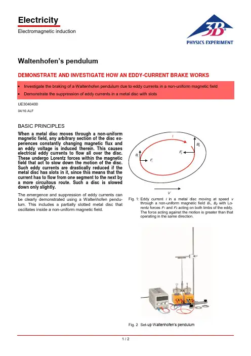
ElectricityElectromagnetic induction1 / 2Waltenhofen’s pendulumDEMONSTRATE AND INVESTIGATE HOW AN EDDY-CURRENT BRAKE WORKSUE304040004/16 ALFBASIC PRINCIPLESWhen a metal disc moves through a non-uniform magnetic field, any arbitrary section of the disc ex-periences constantly changing magnetic flux and an eddy voltage is induced therein. This causes electrical eddy currents to flow all over the disc. These undergo Lorentz forces within the magnetic field that act to slow down the motion of the disc. Such eddy currents are drastically reduced if the metal disc has slots in it, since this means that the current has to flow from one segment to the next by a more circuitous route. Such a disc is slowed down only slightly.The emergence and suppression of eddy currents can be clearly demonstrated using a Waltenhofen pendu-lum. This includes a partially slotted metal disc thatoscillates inside a non-uniform magnetic field.VFig. 1: Eddy current I in a metal disc moving at speed v through anon-uniform magnetic field B 1, B 2 with Lo-rentz forces F 1 and F 2 acting on both limbs of the eddy. The force acting against the motion is greater than that operating in the same direction.Fig. 2 Set-up Waltenhofen’s pendulumUE3040400 3B SCIENTIFIC® PHYSICS EXPERIMENT3B Scientific GmbH, Rudorffweg 8, 21031 Hamburg, Germany, © Copyright 2016 3B Scientific GmbHLIST OF APPARATUS1 Waltenhofen’s pendulum 1000993 (U8497500) 1 Stand base, 150mm 1002835 (U13270) 1 Stand rod, 750mm 1002935 (U15003) 1 Universal clamp1002830 (U13255) 1 Horseshoe magnet 1000979 (U8497215) 1 Pair of pole pieces 1000978 (U8497200) 1 Pair of clamps1000977 (U8497181) 2 Coils with 1200 turns each1000989 (U8497440)1 DC power supply unit 20 V, 5 A @230 V1003312 (U33020-230) or1 DC power supply unit 20 V, 5 A @115 V 1003311 (U33020-115) 1 Set of 15 safety connecting leads 1002843 (U138021)SET-UP∙Set up an electromagnet consisting of a horseshoe magnet, two coils with 1200 windings each and two pole pieces.∙ Connect the coils in series to the DC power supply unit.∙ Firmly attach the aluminium disc to the slotted area inside the pendulum rod.∙Mount the stand rod in the stand base. Use the universal clamp to attach the magnetised rod to the stand rod and suspend the Waltenhofen pendulum from it.∙Arrange the apparatus in such a way that the sec-tion of the aluminium disc without any slots can os-cillate freely between the tips of the pole pieces and the pendulum can come to a state of rest between these pole pieces.∙Select the smallest possible distance between the pole pieces before attaching them, making sure that this does not obstruct the motion of the pendulum.EXPERIMENT PROCEDURE∙ Gradually increase the current passing through the electromagnet in stages.∙ Displace the pendulum from its state of rest and observe its oscillations.∙ Firmly attach the aluminium disc to the area without slots and repeat the procedure.SAMPLE MEASUREMENTSTable 1: Number of oscillations of the aluminium disc in the magnetic field after being deflected from its state of rest. The pole pieces are at a distance of 8mm and the deflection is approx. 7cm.EVALUATIONWhen the side of the metal disc without slots moves through the non-uniform magnetic field, its oscillation is damped. The damping increases with the magnitude of the magnetic field. Eddy currents are induced within the disc and the non-uniform magnetic field exerts a force on the eddy currents that opposes their motion (c.f. Lenz’s Law).If the slotted side of the metal disc moves through the non-uniform magnetic field, the damping of the motion is only slight since it is much more difficult for the eddy currents to form.RESULTSEddy currents are induced in a metal disc which moves within a non-uniform magnetic field. This non-uniform magnetic field exerts a force on the eddy currents that op poses their motion (c.f. Lenz’s Law).In the slotted aluminium disc, it is difficult for eddy cur-rents to form.。

In This Section…Overview............................................................................K-2–K-3Insulating Piercing ConnectorsSplices..........................................................................K-4–K-5Ring Terminals......................................................................K-6Fork Terminals......................................................................K-7Disconnects..........................................................................K-7Taps.....................................................................................K-8Washers...............................................................................K-8Magnet Wire Ordering Information........................................K-8Manual Installation Tools............................................................K-9Battery-Powered Crimping Tool................................................K-10Air Hydraulic Tools..........................................................K-11–K-13Cross Reference.......................................................................K-14InsulationPiercing ConnectorsInsulation Piercing ConnectorsUnited States Tel:901.252.8000800.816.7809Fax:901.252.1354Technical Services Tel:888.862.3289OverviewThe tough, high-temperature insulation on magnet wire used by electrical motor and transformer manufacturers creates problems in splicing and terminating. The durability of magnet wire insulation has made dip-soldering or brazing extremely difficult without stripping the insulation. Another splicing and terminating challenge involves the use of aluminum for magnet applications. A manufacturer connecting aluminum magnet wire to copper is faced with the problem of the different coefficients of thermal expansion of the two metals, galvanic corrosion, cold flow, and the rapid formation of oxide film on the wire surface.T&B offers a solution for a highly reliable connection method for magnetwire. It eliminates welding, no longer requires removal of insulation, and it can be installed in seconds. No special operator skills are needed. The connector and matching tooling do the entire job. To meet the essential requirements of magnet wire connections, T&B offers the insulation piercing Dragon Tooth ®compression connector.Splice, tap and terminate magnet wire quickly and easily!Dragon Tooth ®Magnet Wire ConnectorsThomas & Betts Dragon Tooth ®connectors and installing tools are designed to splice, tap,and terminate magnet wire from 32 AWG to 460,000 CMA copper and from 20 AWG to 460,000 CMA aluminum conductors in motor and transformer applications. Dragon Tooth ®Magnet Wire Connectors penetrate the insulation and oxide layers to make electrical contact on magnet wiring. The result is permanent, low-resistance electrical connections,capable of maintaining contact integrity throughout the life of the connection.•Designed to penetrate magnet wire insulation during application,eliminating the need for stripping, brazing, welding, or other methods of joining magnet wire •Can be installed in seconds•Requires minimal training for installation•Made of copper alloy, tin plated, with teeth on the inner surface •Splices and taps have an open side enabling easy access to wire and making internal coil tapping possible•For aluminum to copper, aluminum to aluminum, or copper to copper magnet wire connections•Supplied with bolt holes to accommodate No. 6 through 1⁄2" studs and includes male and female .250 x .032" disconnects•Splices and fork terminals accommodate wire sizes 24 AWG to 12AWG in a variety of combinations, including combining magnet wire with stripped wire lead. For solid or stranded wire #20 to #4/0 AWG •Larger connectors accommodate circular mil range from 50,000 to 460,000 cm•Connector and matching tooling do the entire jobI n s u l a t i o n P i e r c i n g C o n n e c t o r sTransformer manufacturers depend on Dragon Tooth ®connectorsfor reliable magnet wire applications.Typical ApplicationsParallel SpliceTapTerminationSpliceK-2United States Tel:901.252.8000800.816.7809Fax:901.252.1354Technical Services Tel:888.862.3289OverviewDragon Tooth ®connectors transform the perpendicular compression force, which would normally contribute to conductor creep, into distributive forces that effectively resist cold flow, as indicated by the illustration below .These connectors are made of copper alloy, tin plated, with a number of teeth on the inner surface. When compressed onto an insulated magnet wire, the sharp,hardened teeth penetrate both the insulation and oxide and bite into the conductor.An electrically sound, low-resistance connection is established as a result of the combination of high pressures at the edges of the teeth, and the sliding action between the teeth and the conductor. The open barrel design permits midspansplicing and tapping.How to Select a ConnectorDetermine total circular mil area (CMA). All wires to be installed in a connector barrel including stripped, stranded wire. For example, two #6 AWG = 52480CMA.Refer to Circular Mil column of chart and find the connector series corresponding to the total CMA. For example, 204XXX.Next, refer to either Round Wire column or Rectangular Wire column, depending on the type you are using, and check for any limitations, (such as max. wire width/height). If there are limitations, you may have to make a selection from the next larger size.Select the tool and die appropriate for the application.Insulation Piercing Connectors1234Dragon Tooth ®connectors transform the perpendicular compression force,which would normally contribute to conductor creep, into distributive forces that effectively resist cold flow.These connectors are made of copper alloy, tin plated, with a number of teeth on the inner surface. When the connector is compressed onto an insulated magnet wire, the sharp, hardened teeth penetrate the insulation and the oxide and bite into the conductor. An electrically sound, low-resis t ance connection is established as a result of the combination of high pressures at the tip and edges of the teeth, and the sliding action between the teeth and the conductor.For wire sizes and combinations other than shown, contact Thomas & Betts Technical Services at 800-888-0211, ext. 8324.For square or rectangular wire:Thickness x Width x 1.273 x 106= CMAFor round wire:Diameter 2x 106= CMA(or see chart on p. K-8)Formula for Calculating Circular Mil Area (CMA)K-3United States Tel:901.252.8000800.816.7809Fax:901.252.1354Technical Services Tel:888.862.3289Insulating Piercing ConnectorsSplices•Penetrate all standard copper and aluminum magnet wire insulations•Perfect for heavy Formvar, poly-thermaleze,polyester, and polyurethane insulationsROUND WIRE RECTANGULAR DIMENSIONS (IN.)CIRCULAR RANGE (AWG)WIRE RANGE (IN.)PKG.CAT NO.A B C D*MIL AREAMIN. MAX.THICKNESSWIDTHQTY.214420.43.25.22.135–21 (4) - 13 (2)––1000220004.17.11.08.03468 – 1,72432 - 24**––†8400†220001.34.17.14.091,277 – 4,20526 - 17**.02 - .04.02 - .09†3000†220002-TB .34.25.18.092,985 – 6,68724 - 14**.02 - .05.02 - .10†3000†220006.47.25.19.095,162 – 12,33016 - 12.05 - .08.05 - .16†2500†22L004.15.11.09.03128 – 2,02832 - 24**––100022L001.32.16.16.10808 – 5,16226 - 17**.02 - .04.02 - .10100022L002.32.25.19.102,048 – 9,11024 - 15**.02 - .05.02 - .11100022L006.44.25.22.132,580 – 12,33016 - 12.05 - .08.05 - .16100022L008.70.50.35.1312,960 – 30,55018 - 14.04 - .06.06 - .3810022L009.70.55.46.2036,120 – 86,00016 - 5.08 - .18.08 - .3810022L010.70.78.71.2269,750 – 173,090 (f)–.10 - .23 (GU) .10 - .18 (AL).30 - .63210214S .63.38.37.174,110 – 20,76014(a) - 10.08 - .09.08 - .182********S .69.53.53.2510,380 – 52,48012(b) - 4(e).10 - .16.10 - .26100204210SH .69.53 1.05.4820,760 – 104,96012(c) - 2(d).10 - .16.10 - .2610022L009H .70.55.93.3772,000 – 132,00016 - 5.08 - .18.08 - .38100220015 1.50.88.77(e)50,000 – 115,00010 - 6.100 - .175.300 - .62550220019 1.50 .88 .85(e)110,000 – 175,000 6 - 2.175 - .250.300 - .62525220023 1.75.88.93(e)165,000 – 230,000 2 - 1/0.250 - .325.300 - .62525314118S .63.38.30.143,260 – 12,33015 - 13.05 - .06.05 - .182******** 3.13 .88 .77(e)50,000 – 115,00010 - 6.100 - .175.300 - .62525220020 3.13.88.85(e)110,000 – 175,000 6 - 2.175 - .250.300 - .62525220024 3.63.88.93(e)165,000 – 230,000 2 - 1/0.250 - .325.300 - .62525BCADFor special insulations, consult Technical Services.*Reference dimension. See installing die illustration for gauging.** Not recommended for aluminum magnet wire finer than 21 gauge. (a) Four wires max. (b) Six wires max. (c) Six wires max.each barrel (d) Conductors heavier than 6 AWG require special dies. Contact Thomas & Betts for assistance.(e) Crimping dies may not bottom. Connector height will depend on number and size of wires in barrel. Pump must deliver 9800 psi minimum. (f) Copper CMA, aluminum CMA=52,136–124,561.† On a reel(a) This space may be used for terminal tongue insert, stripped stranded copper wire, stripped copper magnet wire, or left empty.NOTE:Wire sizes and combinations shown have been tested to and meet or exceed Thomas & Betts specifications. Connectors may be suitable for other wire sizes or combinations. Thomas & Betts sells these connectors with the understanding that the user will perform necessary tests to determine their suitability for the intended purpose.I n s u l a t i o n P i e r c i n g C o n n e c t o r sSplices for copper and aluminum magnet wire!123456789123456789K-4United States Tel:901.252.8000800.816.7809Fax:901.252.1354Technical Services Tel:888.862.3289Insulating Piercing ConnectorsSee note (a).BECABD ECA(a) This space may be used for terminal tongue insert, stripped stranded copper wire, stripped copper magnet wire, or left empty.NOTE:Wire sizes and combinations shown have been tested to and meet or exceed Thomas & Betts specifications.Connectors may be suitable for other wire sizes or combinations. Thomas & Betts sells these connectors with the understanding that the user will perform necessary tests to determine their suitability for the intended purpose.Insulation Piercing ConnectorsSplices (continued)101110111110Lower Half .10 - .25.10 - .92Upper Half .25 max 1.03 max.Lower Half .08 - .15.08 - .49Upper Half .25 max .75 max.For Conn 210214MT For Conn204210MTROUND WIRERECTANGULAR STUD DIMENSIONS (IN.)CIRCULAR RANGEWIRE RANGE (IN.)PKG.CAT. NO.SIZEABCDEMIL AREA(AWG)THICKNESS WIDTHQTY.210214MT –.63.63.75.25.1920,000 – 105,000 5 - 13250210MT141/4 1.00 1.44.81–.08 5 - 1325210MT383/8 1.00 1.44.81–.08 5 - 1325204210MT –.69.941.03.25.2590,000 – 215,000 3 - 10100204MT141/4 1.00 1.44.91–.10 3 - 1025204MT383/81.00 1.44.91–.103 - 1025K-5United States Tel:901.252.8000800.816.7809Fax:901.252.1354Technical Services Tel:888.862.3289Insulating Piercing Connectors ROUND WIRERECTANGULARSTUD DIMENSIONS (IN.)CIRCULAR RANGEWIRE RANGE (IN.)PKG.CAT. NO.SIZEABCD*E*MIL AREA(AWG)THICKNESS WIDTHQTY.31412510.38.56 1.22.41.143,260 - 12,33015 - 13.05 - .06.05 - .182503141231⁄4".38.56 1.41.41.143,260 - 12,33015 - 13.05 - .06.05 - .182502102198.38.56 1.22.41.174,110 - 20,76014(a) - 10.08 - .09.08 - .1825021021710.38.56 1.22.41.174,110 - 20,76014(a) - 10.08 - .09.08 - .182502102161⁄4".38.56 1.41.41.174,110 - 20,76014(a) - 10.08 - .09.08 - .1825020421710.53.61 1.58.50.2510,380 - 52,48012(b) - 4(c).10 - .16.10 - .261002042121⁄4".53.61 1.58.50.2510,380 - 52,48012(b) - 4(c).10 - .16.10 - .26100210214-11⁄4".38.56 1.41.69.174,110 - 20,76014(a) - 10.08 - .09.08 - .182********-25⁄16".38.56 1.41.69.174,110 - 20,76014(a) - 10.08 - .09.08 - .182********-33⁄8".38.56 1.41.69.174,110 - 20,76014(a) - 10.08 - .09.08 - .182********-11⁄4".53.61 1.58.81.2510,380 - 52,48012(b) - 4(c).10 - .16.10 - .26100204210-25⁄16".53.61 1.58.81.2510,380 - 52,48012(b) - 4(c).10 - .16.10 - .26100204210-33⁄8".53.61 1.58.81.2510,380 - 52,48012(b) - 4(c).10 - .16.10 - .26100204210-51⁄2".53.61 1.58.81.2510,380 - 52,48012(b) - 4(c).10 - .16.10 - .26100204210-1H 1⁄4".53.61 1.58.81.4720,760 - 104,96012(b) - 4(c).10 - .16.10 - .26100204210-3H 3⁄8".53.61 1.58.81.4720,760 - 104,96012(b) - 4(c).10 - .16.10 - .261002200173⁄8".88 1.50 2.76 1.06(d)50,000 - 115,000.100 - .175–.300 - .625252200181⁄2".88 1.50 2.76 1.06(d)50,000 - 115,000.100 - .175–.300 - .625252200213⁄8".88 1.50 2.76 1.06(d)110,000 - 175,000–.175 - .250.300 - .625252200221⁄2".88 1.50 2.76 1.06(d)110,000 - 175,000–.175 - .250.300 - .625252200253⁄8".88 1.50 2.76 1.06(d)110,000 - 230,000- .175 - .325.300 - .625252200261⁄2".88 1.50 2.76 1.06(d)110,000 - 230,000- .175 - .325.300 - .6252522R061**6.16.32.78.30.10404 - 410015 - 24.02 - .05.02 - .10100022R081**8.16.32.78.30.10404 - 410015 - 24.02 - .05.02 - .10100022R101**10.16.32.78.30.10404 - 410015 - 24.02 - .05.02 - .10100022R0868.25.45.91.30.132,580 - 12,33012 - 16.05 - .08.05 - .16100022R10610.25.45.91.30.132,580 - 12,33012 - 16.05 - .08.05 - .16100022R1461⁄4".25.45.95.42.132,580 - 12,33012 - 16.05 - .08.05 - .16100022L010*BDCAE*Reference dimension. See installing die illustration for gauging. (a) Four wires max. (b) Six wires max. (c) Conductors heavier than 6 AWG require special dies. Contact Thomas & Betts for assistance. (d) Crimping dies may not bottom.Connector height will depend on number and size of wires in barrel. Pump must deliver 9800 psi minimum.NOTE:Wire sizes and combinations shown have been tested to and meet or exceed Thomas & Betts specifications.Connectors may be suitable for other wire sizes or combinations. Thomas & Betts sells these connectors with the understanding that the user will perform necessary tests to determine their suitability for the intended purpose.**22-24 AWG and equivalent rectangular c.m.a., copper only.Ring TerminalsSecure connections easily!1234561112234556I n s u l a t i o n P i e r c i n g C o n n e c t o r sK-6United States Tel:901.252.8000800.816.7809Fax:901.252.1354Technical Services Tel:888.862.3289Insulating Piercing ConnectorsConnectors for every application!Durable and convenient!Fork TerminalsDisconnectsBDCAEBDCAEROUND WIRERECTANGULAR STUD DIMENSIONS (IN.)CIRCULAR RANGEWIRE RANGE (IN.)PKG.CAT. NO.SIZEABCD*E*MIL AREA(AWG)THICKNESS WIDTHQTY.22F061**6.16.32.78.30.10404 - 410015 - 24.02 - .05.02 - .10100022F081**8.16.32.78.30.10404 - 410015 - 24.02 - .05.02 - .10100022F101**10.16.32.78.30.10404 - 410015 - 24.02 - .05.02 - .10100022F0666.25.45.91.30.132,580 - 12,33012 - 16.05 - .08.05 - .16100022F0868.25.45.91.30.132,580 - 12,33012 - 16.05 - .08.05 - .16100022F10610.25.45.91.30.132,580 - 12,33012 - 16.05 - .08.05 - .161000210219F 6.25.45.91.30.132,580 - 12,33012 - 16.05 - .08.05 - .161000210217F 8.25.45.91.30.132,580 - 12,33012 - 16.05 - .08.05 - .161000210216F10.25.45.91.30.132,580 - 12,33012 - 16.05 - .08.05 - .161000ROUND WIRERECTANGULAR TAB DIMENSIONS (IN.)CIRCULAR RANGEWIRE RANGE (IN.)PKG.CAT. NO.SIZEABCD*E*MIL AREA(AWG)THICKNESS WIDTHQTY.22LM01**.250 x .032.16.32.76.25.10404 - 410015 - 24.02 - .05.02 - .10100022LM06.250 x .032.25.45.91.25.132,580 - 12,33012 - 16.05 - .08.05 - .16100022LF01**.250 x .032.16.32.79.25.10404 - 410015 - 24.02 - .05.02 - .10100022LF06.250 x .032.25.45.91.25.132,580 - 12,33012 - 16.05 - .08 .05 - .161000*Reference dimension. See installing die illustration for gauging. (a) Four wires max. (b) Six wires max. (c) Conductors heavier than 6 AWG require special dies. Contact Thomas & Betts for assistance. (d) Crimping dies may not bottom.Connector height will depend on number and size of wires in barrel.NOTE:Wire sizes and combinations shown have been tested to and meet or exceed Thomas & Betts specifications.Connectors may be suitable for other wire sizes or combinations. Thomas & Betts sells these connectors with the understanding that the user will perform necessary tests to determine their suitability for the intended purpose.**22-24 AWG and equivalent rectangular c.m.a., copper only.12121212Insulation Piercing ConnectorsK-7United States Tel:901.252.8000800.816.7809Fax:901.252.1354Technical Services Tel:888.862.3289Insulating Piercing Connectors WashersTeeth on the transition washersTapsQuick and easy connections!ConductorsBCASTUD DIMENSIONS (IN.)CAT. NO.SIZE (IN.)ABCAdditional Magnet Wire Ordering Information1. For wire sizes and combinations other than shown,consult factory.2. Maximum of two layers of conductors in each connector.3. Consult factory for gauging other than shown.4. When terminating wires with an AWG size difference of four or more, samples should be tested in completed e c t o r sManual Installation ToolsCrimp with comfort!Ergonomic Manual Installation Tools•Fixed die tool •Incorporates the ergonomically designed Comfort Crimp ®tool handles,which distribute the force more evenly across the hand •Shure-Stake ®mechanism ensures a complete crimp cycle before the tool releases•Rubberisedthermoplastic handles combine maximumERG1806Battery-Powered Crimping Tools •Interchangeable dies can be quickly changed to crimp non-insulated and insulated terminals up to 6 AWG •Dies are the same as our hand tools—crimps will be exactly the same between Sta-Kon ®hand tools such as our ERG-2001 and the new BAT22-6•360° rotating head gives the user the added flexibility when crimping hard-to-reach connections•Short cycle time equates to crimping times of less than two seconds•Quick, lightweight, and maneuverable•NiCd battery operation provides long-lasting battery life to complete up to 150 crimps on a single charge•Extra battery and charger are included with the tool, ensuring round-the-clock operation •Battery charger provides full battery life in under an hour •Linear crimping motion gives a symmetric, high-quality crimp every timeBattery-Powered Crimping Tool —BAT22-611⁄2tons of grip that weighs less than three pounds!Crimping Force —2,900 lbs. max.Wire Crimping Range —Up to 6 AWG Crimp Cycle Time —2 seconds Power Supply —9.6V NiCd battery Recharging Time —1 hourCrimps per Charge —150Dimensions —25.4" (645 mm) Length 3.1" (79 mm) Width 2.1" (53 mm) Height Tool Weight (With Battery) —23⁄4lbs.CAT. NO. DESCRIPTION PKG. QTY.BAT22-6Battery Crimping Tool 1.5 Ton with 120 VAC Charger 1Crimp Dies*DIE180122 F,L,R-1 Series 1DIE180222L0021DIE180422L0041DIE180622 F,L,R-6 Series1Tool purchase includes crimping tool, two 9V batteries, charger, and case.*Dies sold separately.Easy to rotate with your wrist—delivers fast and effective crimping power.. . . . . . . . . . . . . . . . . . Specifications . . . . . . . . . . . . . . . . . .T&B’s newest battery-powered tool is fast and portable for making high-volume and difficult-to-reach terminal installations in a snap. The BAT22-6 delivers 1.5 tons of crimping force with an easy, pushbutton trigger. The lightweight, ergonomic design minimizes the risk of repetitive motion injuries that can occur with traditional hand crimping tools. And at less than three pounds, one-hand operation is easy while still packing enough power to crimp up to 6 AWG terminals in seconds.Included Accessories•Sturdy, plastic carrying case for portability •Two 9.6V NiCd batteries and battery charger •Sturdy tray for convenient storage of crimp diesUses the exact dies of theComfort Crimp line of ergonomic tools for Sta-Kon, Spec-Kon, and Dragon Tooth.I n s u l a t i o n P i e r c i n g C o n n e c t o r sK-10United States Tel:901.252.8000800.816.7809Fax:901.252.1354Technical Services Tel:888.862.3289Air Hydraulic ToolsPneumatic power!Continuous reel crimping!Perfect for high-speed installation!Installing Dies for BAIR22-6and PAIR22-6PAIR22-6 — Heavy-Duty Portable Air Crimp Tool•Installs Dragon Tooth ®terminals •Hand actuated•Delivers 1.25 tons of crimping force at 100 psi • 3 interchangeable dies can crimp the 22xxx1, 22xxx2, and 22xxx6 series terminalsAuto-Feed Tool for Magnet Wire Connectors on Strip•Foot pedal contains T&B Shure-Stake ®control mechanism, which ensures a full compression each time •Insulation piercing connectors are fed on a continuous reel-mounted strip •Dies are self-contained •Includes foot valve, hoses, and air treatment system •Pneumatic bench-mounted foot-operated tool for crimping copper or aluminum magnet wire and copper lead wire, not solder dipped or bondedBAIR22-6 — Heavy-Duty Bench-Top Air Crimp Tool•Bench mounted for stability and operator control •Compact size, all-metallic construction •Delivers 1.8 tons of crimping force at 100 psi •Heavy-duty and installs wide range of Dragon Tooth connectors PAIR 22-6CAT. NO.DESCRIPTIONPAIR22-6Open “C” Yoke; Hand ActuatedCAT. NO.DESCRIPTIONBAIR22-6Equipped with Shure-Stake ®Mechanism, Ensuring Full Crimp Cycle Before ReleaseCAT. NO.CONNECTORQUANTITY PER REELWEIGHT WIDTHDEPTHHEIGHT13676A 2200049,00019 lbs.5"14"11"136782200013,00028 lbs.6"18"14"136792200023,00028 lbs.6"18"14"136962200062,50032 lbs.6"18"16"BAIR22-6CAT. NO.DESCRIPTIONPKG. QTY.Crimp Dies*DIE180122 F,L,R-1 Series 1DIE180222L0021DIE180422L0041DIE180622 F,L,R-6 Series 1. . . . . . . Specifications . . . . . . . .Height —12"Operating Pressure —85–100 psi Base —8" Square Weight —17 lbs.. . . . . . . . . . . . . . . Specifications . . . . . . . . . . . . . .Overall Length — 14"Diameter —21⁄4"Operating Pressure —90–100 psi Weight —2.5 lbs.Insulation Piercing ConnectorsUnited States Technical ServicesAir Hydraulic Tools 6-Ton Hydraulic Head•Lightweight design—weighs less than 7 lbs. including dies •Includes steel carrying caseRugged and portable!CAT. NO.DESCRIPTIONPKG. QTY13100ARemote 14-Ton Hydraulic Head (Dies Ordered Separately)1See die chart on page K-14for complete listing of dies and connectors used with 13100A.Die Release KnobRetainer PinCAT. NO.DESCRIPTIONTBM6HThe TBM6H Remote Hydraulic Crimping Head is a lightweight but powerful compression tool. The TBM6H operates from any 10,000 psi hydraulic pump.See die chart on page K-14for complete listing of dies and connectors used with TBM6H.. . . . . . . . . . . . . . . . . . Specifications . . . . . . . . . . . . . . . . . .CAT. NO.DESCRIPTIONPKG. QTY.1340012-Ton Hydraulic Head (Dies Ordered Separately)1See die chart on page K-14for complete listing of dies and connectors used with 13400.Output — 12 tons (nominal)Hydraulic Operating Pressure — 10,000 psi (max.)Length (with coupling)— 141⁄2"Width — 31⁄4"Weight (without dies) — 15 lbs.. . . . . . . . . . . . . . . . . . Specifications . . . . . . . . . . . . . . . . . .Output Force — 6 tons nominalOperating Pressure — 10,000 psi nominal (safety bypass on pump set at 9800 psi)Tool Weight — 61⁄2lbs. (without dies)Tool Dimensions — 131⁄2" long, 31⁄2" wide •Tool carrying case included •Dies are ordered as a set (2 pieces)•Upper and lower dies are identical. . . . . . . . . . . . . . . . . . Specifications . . . . . . . . . . . . . . . . . .Lightweight design!14-Ton Hydraulic Head•14 tons output (nominal)•10,000 psi max. hydraulic operating pressure •Weighs 10 lbs.Powerful and reliable!12-Ton Hydraulic Head•12 tons output (nominal)•10,000 psi max. hydraulic operating pressure •Weighs 15 lbs.I n s u l a t i o n P i e r c i n g C o n n e c t o r sOutput — 14 tons (nominal)Hydraulic Operating Pressure — 10,000 psi (max.)Length (With Coupling)— 111⁄2in.Width — 21⁄2"Height — 41⁄4"Piston Diameter — 1.812"Piston Stroke — 1.5" max.Weight (Without Dies)— 10 lbs.Air Hydraulic Tools15-Ton Hydraulic Head•Longer, slimmer profile enables easier access into tight spaces •Wider jaw opening eases crimping of larger connectors •Head made of forged steel and insulated with rubber boot •Steel carrying case is included•Longer, slimmer profile enables easier access into tight spaces Crimp larger connectors easily!CAT. NO.DESCRIPTIONPKG. QTYTBM15IInsulated 15-Ton Hydraulic Tool; Carrying Case Included 1See die chart on page K-14for complete listing of dies and connectors used with TBM15I.15500-TB AdapterCAT. NO.DESCRIPTION13810Electric hydraulic pump, 10000 psi with Shure-Stake mechanism feature; this is a heavy-duty OEM pump with high flow rate; 115V, 60Hz, 11⁄2HP, 23A; requires hand or foot control.You may also need…13611Hand Switch for 1381013612Foot Switch for 1381013613High Pressure, Steel Reinforced Hydraulic Hose; 6 ft.13614High Pressure, Steel Reinforced Hydraulic Hose; 10 ft.13619High Pressure, Plastic Hydraulic Hose; 10 ft.13600This electric hydraulic pump is for use with all T&B hydraulicheads—consists of pump with pressure gauge and Pioneer type male coupler; add suffix WG to eliminate gauge; output pressure 9800 psi; order switch and hose separately.You may also need…13620Hand Switch—10 ft.13589A Foot Switch—10 ft.1361910-ft. Non-Metallic Hose 1361820-ft. Non-Metallic HoseA remote control switch is required. Order Cat. No. 13620 for hand operation or Cat. No. 13589A for foot operation.All pumps are supplied with a metal carrying case.13610AShure-Stake ®electric hydraulic pump has same features as 13600, but includes the Shure-Stake ®control mechanism; prevents under crimping; (pump pressure must reach 9,800 psi before recycling); requires hand or foot control; order switch and hose separately.You may also need…13611Hand Switch—10 ft.13612Foot Switch—10 ft.13797In-line hydraulic pressure inspection gauge with male and femalepioneer-type coupler.A remote control switch is required to operate this unit. Use either a #13611 (hand) or #13612 (foot) switch.1381013610AElectric Hydraulic Pump•Up to 10,000 psi output pressure •Durable construction •Hand or foot actuatedOutput Force — 15 tons nominal Operating Pressure — 10,000 psi nominal Cylinder — 2" dia.Tool Weight — 161⁄2lbs. (without dies)Installs — 8 AWG – 1500 MCM Copper; 10 AWG – 1000 MCM Aluminum. . . . . . . . . . . . . . . . . . Specifications . . . . . . . . . . . . . . . . . .Insulation Piercing ConnectorsUnited States Technical ServicesCross ReferenceAn easy-to-use reference guide for tools and connectors!AUTOFEED TOOL MANUALBATT 22-6. BAIR 22-6, PAIR 22-6FOR STRIP TBM6H13100A13400TBM15ICONNECTORDIES204210MT –––––13682–204210S ––––13671B 13671A 13671B with 15500TB 204210SH ––––13673B 1367313673B with 15500TB 204210-1––––13671B 13671A 13671B with 15500TB 204210-1H ––––13673B 1367313673B with 15500TB 204210-2––––13671B 13671A 13671B with 15500TB 204210-3––––13671B 13671A 13671B with 15500TB 204210-3H ––––13673B 1367313673B with 15500TB 204210-5––––13671B 13671A 13671B with 15500TB 204212––––13671B 1367113671B with 15500TB 204217––––13671B 13671A 13671B with 15500TB204MT14–––––––204MT38–––––––204T14––––13689B –13689B with 15500TB 204T38––––13689B –13689B with 15500TB 210214MT ––––13681B 1368113681B with 15500TB 210214S ––––13670B 13670A 13670B with 15500TB 210214-2––––13670B 13670A 13670B with 15500TB 210214-3––––13670B 13670A 13670B with 15500TB 210216, 210216F ––––13670B 13670A 13670B with 15500TB 210217, 210217F ––––13670B 13670A 13670B with 15500TB 210219, 210219F ––––13670B 13670A 13670B with 15500TB210MT14–––––––210MT38–––––––214420ERG811/WT811DIE 811–––––220001––13678––––220002-TB ––13679––––220004––13676A ––––220005––13690––––220006––13696––––220015––––13713–137********––––13713–137********––––13713–137********––––13713–137********––––13713–137********––––13713–137********––––13713–137********––––13713–137********––––13713–137********––––13713–137********––––13713–137********––––13713–1371322F061ERG1801DIE1801–––––22F066ERG1806DIE1806–––––22F081ERG1801DIE1801–––––22F086ERG1806DIE1806–––––22F101ERG1801DIE1801–––––22F106ERG1806DIE1806–––––22L001ERG1801DIE1801–––––22L002ERG1802DIE1802–––––22L004ERG1804DIE1804–––––22L006ERG1806DIE1806–––––22L008–––6TON-MW-0813683B 1368313683B with 15500TB 22L009–––6TON-MW-0913684B 1368413684B with 15500TB 22L009H ––––13686B 1368613686B with 15500TB22LF01ERG1801DIE1801–––––22LF06ERG1806DIE1806–––––22LM01ERG1801DIE1801–––––22LM06ERG1806DIE1806–––––22R061ERG1801DIE1801–––––22R106ERG1806DIE1806–––––22R146ERG1806DIE1806–––––314118S ––––13685B 1368513685B with 15500TB 314123––––13685B 1368513685B with 15500TB 314125––––13685B 1368513685B with 15500TB22L010––––13690BI n s u l a t i o n P i e r c i n g C o n n e c t o r sNOTE:Dies that fit 13100A also work in TBM15 with use of adapter 15500TB.。


e-mail:**************For latest product manuals: Shop online at User’sGuideEP510, IP510, EP511, IP511 SERIES ELECTROPNEUMATIC CONVERTERSThe information contained in this document is believed to be correct, but OMEGA accepts no liability for any errors it contains, and reserves the right to alter specifications without notice.Servicing North America:U.S.A.Omega Engineering, Inc.Headquarters:Toll-Free: 1-800-826-6342 (USA & Canada only)Customer Service: 1-800-622-2378 (USA & Canada only) Engineering Service: 1-800-872-9436 (USA & Canada only) Tel: (203) 359-1660 Fax: (203) 359-7700 e-mail:**************For Other Locations Visit /worldwide***********************California Proposition 65WARNING: Cancer and Reproductive Harm !AIR CONNECTIONSSUPPLYConnect air supply to 1/4 NPT port marked "IN." If the above specifications are not met, possibility of internal clogging exists. Also see MAINTENANCE section.OUTPUTConnect output to 1/4 NPT port marked "OUT.”GAUGEThe plugged 1/8 NPT port in the base of the transducer is internally connected with the "OUT" port. A pressure gauge can be attached to this port to monitor output pressure.WARNINGIn order to get optimal service from this transducer and ensure warranty coverage the following MUST be followed:ŸThe supply air quality to this instrument must be instrument quality air as defined by ISA Standard 57.0.01-1996.1. Dew point not higher than 35˚F.2. No particulates larger than 3 microns in size.3. Maximum oil content of 1 ppm.ŸNo mechanical adjustments or calibrations are necessary or allowed. All calibration MUST be done with electrical potentiometers on the enclosed circuit board only. See “CALIBRATION” section of instructions for more information.3M4109/0719 IP510, EP510, IP511, EP511 SERIESA 4MOUNTINGGENERALNEMA 1 and NEMA 4X transducers can be mounted in any position.DIRECT MOUNTING PIPEŸAny NEMA 1 transducers may be supported by its own plumbing for air supply and output. NEMA 4X transducers may also be supported using 1/2" explosion proof conduit in the electrical port.PANELŸNEMA 1 transducers may be mounted to a panel with two No. 10-32 screws using threaded holes in the back of a transducer or with two to four No. 8-32 screws using threaded holes in the bottom of a transducer.ŸNEMA 4X transducers may be mounted to a panel with three No. 10-32 screws using threaded holes in the back of a transducer or with four No. 8-32 screws using threaded holes in the bottom of a transducer. In the case of back-mounting, if the panel extends towards the screw-on cover, a 3/16-inch-thick spacer MUST be used between the back of the transducer and the panel in order for the panel to clear the transducer's screw-on cover.EP510 AND IP510WE I V E D I S W E I V T N O RF WE I V P O T BOTTOM VIEW Drawings and dimensions are for reference only.5DIRECTIONS 1.Remove the cover (see WARNING above).2. Bring wiring to the terminal block, located on the circuit board, through 1/2 NPT electrical conduit connection. 18 A.W.G. is recommended; 14 A.W.G. is the maximum wire size. Connect wires to the terminal block per TABLE 2. Care must be exercised to prevent damage to delicate internal parts when inserting wiring through the 1/2” NPT conduit opening.3. An internal grounding screw is provided on all units to facilitate separate ground when required. An external grounding lug is also provided on NEMA 4X enclosures.4.Reinstall the cover tightly using all o-rings and locking devices to insure compliance with Agency Approvals.ELECTRICAL CONNECTIONSPRECAUTIONS TO BE OBSERVED DURING INSTALLATIONThe Transducers were tested at the EMC Test Centre, Dunfermline, Fife, KY11 5LB to the Electromagnetic Compatibility Directive effective January 1, 1996. The relevant EMC specifications tested were the following: EN 50081-1 (1992) and EN 50082-1 (1992). A Technical Construction File, Serial #107 was written and Certificate of Conformity issued by a Competent Body.EN 50081-1 (1992): Test results confirmed that no precautions need to be observed during installation regarding electro-magnetic emissions from the IP510A Transducers.EN 50082-1 (1992): The following precautions should be taken during installation to maintain the advertised accuracy specifications for the Transducers. The input wiring to the transducer should be isolated from other high voltage transient wiring. The momentary switching on and off of nearby relays, motors, or other high capacitive or inductive loads can have a minor effect on the terminal based linearity specification (1.0% of span, standard range models). Any change in output pressure is minimal and momentary, and is considered to be within its performance capabilities. Use of a ferrite bead collar on the input wires entering the transducer is recommended shouldinstallation next to high electromagnetic interference be necessary.WARNING1.Remove the cover to gain access to the “SPAN”, (marked S), “FINE ZERO”, (marked Z) and the “DAMPING”, (3/4 turn low profile ) potentiometers. The unmarked pot “COURSE ZERO”, is used only for major calibration range changes. This adjustment should only be attempted by factory trained personnel. For NEMA 1 enclosure, just slide open the access door on the top of the cover.2.Set electrical input signal to 0% (e.g. 4 mA or 0 VDC ).3. FORWARD ACTING UNITS: Using "FINE ZERO" potentiometer, adjust output pressure to 0% output (e.g. 3 psi).4.Set electrical input signal to 100% (e.g. 20 mA or 10 VDC).5. FORWARD ACTING UNITS: Using "SPAN" potentiometer, adjust output pressure to 100% output (e.g. 15 psi).6. Repeat steps 2 through 5 until output pressures are properly set.NOTE: Under certain circumstances, output pressure may exhibit cycling action. To eliminate this condition, use the “DAMPING”potentiometer.7. Reinstall cover using original screws and gaskets, if equipped.MAINTENANCEWhen used properly, these transducers should provide more than one million cycles without failure. If a situation should occur in which the transducer's behavior is abnormal, the cause is usually related to a pneumatic problem.ELECTRICAL MAINTENANCEAn electrical problem must be isolated by a skilled technician. The power source and all wiring should be checked first. Circuit board failures are very rare, and can be confirmed by the following method. Loosen the screws, or posts that hold the circuit board in place. Unplug the blue connector from the circuit board, and insert two small pieces of wire into the connector.IMPORTANT: Connect a current source with the polarity as follows. Positive to the (RED) coil wire and Negative to the (BROWN) coil wire of 10 mA to the connector, which powers the yellow coil. With supply pressure on, the unit should produce an output pressure equivalent to 80% or more of the maximum output pressure. If there is little or no output, then the unit is clogged. Should it produce an adequate output pressure, then the circuit board is the primary suspect. The unit must be returned to the factory for repair. PNEUMATIC MAINTENANCEAll 510 and 511 Series transducers also have an internal orifice filter, but if contaminates do invade the transducer, they can clog the internal orifice and block the flow, or jam open the internal supply valve. The problem can be corrected through replacement of the orifice (see TABLE 5: KITS) or by cleaning the internal supply valve, or both.6REPLACING ORIFICE:This can be accomplished without removing the unit from its mounting or plumbing.1. Turn off supply pressure and unscrew the brass orifice assembly located on the side of the housing with the gauge port. NOTE: Small sealing o-ring may remain inside of the housing. If it does, remove it with a paper clip or some other small probe. The replacement assembly will contain this o-ring.2. Install the new orifice assembly making sure the o-ring is seated on the end of the screw.CLEANING INTERNAL SUPPLY VALVE:1. Turn off the supply pressure.2. Use a 9/16" socket or wrench to unscrew the brass plug in the bottom of the transducer.NOTE: Take care not to lose the supply valve spring which is retained by the bottom plug.3. Clean out any dirt or debris and reassemble, making sure the stem of the supply valve is nested in the supply valve spring.AGENCY APPROVALS, SPECIAL NOTES, AND CAUTIONSINTRINSIC SAFETYAll 510 and 511 Series transducers are rated intrinsically safe by both FM and CSA for:CLASS I, DIVISION 1, GROUPS A,B,C,D HAZARDOUS LOCATIONS.Proper FM-approved intrinsically-safe wiring requires external FACTORY MUTUAL RESEARCH CORPORATION ENTITY-APPROVED SINGLE-CHANNEL barriers to be selected, based upon MAXIMUM ENTITY PARAMETERS of 510 and 511 Series transducers:ENTITY PARAMETERS:Vmax = 28 V, Imax = 150 mA, Ci = 0.22uF, Li = 0 mH.Voc and Isc of a barrier shall not exceed Vmax and Imax of the transducer.(Li + Lwiring) and (Ci + Cwiring) shall not exceed La and Ca of a barrier.NOTICE: For proper FM and CSA approved intrinsically-safe wiring, request Drawing Number 990-439-000 from the Factory.NONINCENDIVEAll 510 and 511 Series transducers are approved as NONINCENDIVE by FM and approved as suitable by CSA for: CLASS I, DIVISION 2, GROUP A, B, C, D HAZARDOUS LOCATIONS.A barrier is not necessary when these transducers are in these locations.ENCLOSURESCompliance with NEMA 4X and CSA ENC4 enclosure ratings require that the screw-on cover has the O-ring installed. In case of a need for replacement parts, see TABLE 3.78EXPLOSION & DUST-IGNITION PROOF CERTIFICATIONS FACTORY MUTUAL and CANADIAN STANDARDS ASSOCIATIONEXPLOSION PROOF FOR CLASS I, DIV 1, GROUP B, C, D.DUST-IGNITION PROOF FOR CLASS II, DIV 1, GROUP E, F, G.SUITABLE FOR CLASS III LOCATIONS.EP511 AND IP51110Where Do I Find Everything I Need for Process Measurement and Control?OMEGA…Of Course!Shop online at TEMPERATUREThermocouple, RTD & Thermistor Probes, Connectors, Panels & AssembliesWire: Thermocouple, RTD & ThermistorCalibrators & Ice Point ReferencesRecorders, Controllers & Process MonitorsInfrared PyrometersPRESSURE, STRAIN AND FORCETransducers & Strain GagesLoad Cells & Pressure GagesDisplacement TransducersInstrumentation & AccessoriesFLOW/LEVELRotameters, Gas Mass Flowmeters & Flow ComputersAir Velocity IndicatorsTurbine/Paddlewheel SystemsTotalizers & Batch ControllerspH/CONDUCTIVITYpH Electrodes, Testers & AccessoriesBenchtop/Laboratory MetersControllers, Calibrators, Simulators & PumpsIndustrial pH & Conductivity EquipmentDATA ACQUISITIONCommunications-Based Acquisition SystemsData Logging SystemsWireless Sensors, Transmitters, & ReceiversSignal ConditionersData Acquisition SoftwareHEATERSHeating CableCartridge & Strip HeatersImmersion & Band HeatersFlexible HeatersLaboratory HeatersENVIRONMENTALMONITORING AND CONTROLMetering & Control InstrumentationRefractometersPumps & TubingAir, Soil & Water MonitorsIndustrial Water & Wastewater TreatmentpH, Conductivity & Dissolved Oxygen InstrumentsM4109/0719OMEGA’s policy is to make running changes, not model changes, whenever an improvement is possible. This affords our customers the latest in technology and engineering.OMEGA is a registered trademark of OMEGA ENGINEERING, INC.© Copyright 2017 OMEGA ENGINEERING, INC. All rights reserved. This document may not be copied, photocopied, reproduced, translated, or reduced to any electronic medium or machine-readable form, in whole or in part, without the prior written consent of OMEGA ENGINEERING, INC.FOR WARRANTY RETURNS, please have thefollowing information available BEFORE contactingOMEGA:1. P urchase Order number under which the productwas PURCHASED,2. M odel and serial number of the product underwarranty, and3. Repair instructions and/or specific problemsrelative to the product.FOR NON-WARRANTY REPAIRS, consult OMEGA for current repair charges. Have the following information available BEFORE contacting OMEGA:1. Purchase Order number to cover the COST of the repair,2. Model and serial number of the product, and 3. Repair instructions and/or specific problems relative to the product.RETURN REQUESTS/INQUIRIESWARRANTY/DISCLAIMEROMEGA ENGINEERING, INC. warrants this unit to be free of defects in materials and workmanship for a period of 13 months from date of purchase. OMEGA's WARRANTY adds an additional one (1) month grace period to the normal one (1) year product warranty to cover handling and shipping time. This ensures that OMEGA's customers receive maximum coverage on each product.If the unit malfunctions, it must be returned to the factory for evaluation. OMEGA's Customer Service Department will issue an Authorized Return (AR) number immediately upon phone or written request. Upon examination by OMEGA, if the unit is found to be defective, it will be repaired or replaced at no charge. OMEGA's WARRANTY does not apply to defects resulting from any action of the purchaser, including but not limited to mishandling, improper interfacing, operation outside of design limits, improper repair, or unauthorized modification. This WARRANTY is VOID if the unit shows evidence of having been tampered with or shows evidence of having been damaged as a result of excessive corrosion; or current, heat, moisture or vibration; improper specification; misapplication; misuse or other operating conditions outside of OMEGA's control. Components in which wear is not warranted, include but are not limited to contact points, fuses, and triacs.OMEGA is pleased to offer suggestions on the use of its various products. However, OMEGA neither assumes responsibility for any omissions or errors nor assumes liability for any damages that result from the use of its products in accordance with information provided by OMEGA, either verbal or written. OMEGA warrants only that the parts manufactured by the company will be as specified and free of defects. OMEGA MAKES NO OTHER WARRANTIES OR REPRESENTATIONS OF ANY KIND WHATSOEVER, EXPRESSED OR IMPLIED, EXCEPT THAT OF TITLE, AND ALL IMPLIED WARRANTIES INCLUDING ANY WARRANTY OF MERCHANTABILITY AND FITNESS FOR A PARTICULAR PURPOSE ARE HEREBY DISCLAIMED. LIMITATION OF LIABILITY: The remedies of purchaser set forth herein are exclusive, and the total liability of OMEGA with respect to this order, whether based on contract, warranty, negligence, indemnification, strict liability or otherwise, shall not exceed the purchase price of the component upon which liability is based. In no event shall OMEGA be liable for consequential, incidental or special damages.CONDITIONS: Equipment sold by OMEGA is not intended to be used, nor shall it be used: (1) as a “Basic Component” under 10 CFR 21 (NRC), used in or with any nuclear installation or activity; or (2) in medical applications or used on humans. Should any Product(s) be used in or with any nuclear installation or activity, medical application, used on humans, or misused in any way, OMEGA assumes no responsibility as set forth in our basic WARRANTY/DISCLAIMER language, and, additionally, purchaser will indemnify OMEGA and hold OMEGA harmless from any liability or damage whatsoever arising out of the use of the Product(s) in such a manner.Direct all warranty and repair requests/inquiries to the OMEGA Customer Service Department. BEFORE RETURNING ANY PRODUCT(S) TO OMEGA, PURCHASER MUST OBTAIN AN AUTHORIZED RETURN (AR) NUMBER FROM OMEGA'S CUSTOMER SERVICE DEPARTMENT (IN ORDER TO AVOID PROCESSING DELAYS). The assigned AR number should then be marked on the outside of the return package and on any correspondence.The purchaser is responsible for shipping charges, freight, insurance and proper packaging to prevent breakage in transit.。
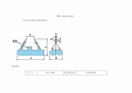
.目录Index1、基本原理和使用条件Basic principle and operating conditions2、产品型号及含义Models and contents3、用途及使用范围Usage and applicable range4、结构及特点Structure and characteristic5、电气性能Electrical property6、型号、技术参数与外形尺寸图Models, technical data, and overall dimension drawing 7、使用注意事项Cautions8、保养及维修Maintenance and service1.基本原理和使用条件 Basic principle and operating conditions1.1 基本原理 Basic principle电磁铁工作时,电源及控制设备向电磁铁供给直流电,电磁铁内部产生强大的磁场,通过壳体磁路和工作气隙对被吸物产生强大磁力而达到搬运物料的目的。
When electromagnet works, the power source and the controlling device supply direct current to the electromagnet. A strong magnetic field will be generated inside the electromagnet, the magnetic field gives enough strong magnetic force on the material through the shell magnetic circuit and the operating clearance to lift the bulk material .1.2 使用条件 using conditions1.2.1 使用地点的海拔高度不超过2000m。
Performance, Reliability, and Servicew w w. E l e ct r ic a l P a rt Ma nu al s . c o2GE Type IP Transformers ...performance, reliability, and service lifeChoosing a brand of dry-type core and coil transformer for your electrical equipment is an important decision. You need a transformer that will perform to your customers' expectations and last longer than the equipment itself. That's why original equipment manufacturers have turned to GE specialty transformers since 1928. From its manufacturing plant in Fort Wayne, Indiana, GE supplies small core and coil transformers that are designed for peak performance, reliability, and service life.Type IP core and coil transformers are made from high quality, grainoriented electrical steel and magnetic wire using GE proprietary processes. Coils are automatically wound by numerically-controlled machines and core and coil assemblies are vacuum impregnated to ensure long lifeand protect the insulation system. All products are assembled by a skilled workforce that averages over 20 years experience; every transformer is proudly tagged with the assembler's name. Each unit is 100% tested per NEMA and ANSI standards using a custom-made automated test equipment system. It's no wonder that in survey after survey, people equate the GE name with quality.In an increasingly competitive world market, it is essential to have equipment designed for world-class quality requirements and systems integration. That's why in addition to complete UL listing and CSA certification on all Type IP ratings, GE has a library of ratings that comply with nondomestic standards. Consult your local GE sales office for availability.And because system compatibility is important in today's complex control schemes, Type IP appearance and performance characteristics are the perfect link in an integrated control system that utilizes GE world-class circuit breakers and controls. New features include:•Top-mounted primary and secondary fuse blocks. The new designs meet all UL and CSA requirements for control transformer protection including the recently adopted UL 508 and 845 standards. The new integral fuse blocks allow panel builders to save valuable panel space and haveflexibility to provide several secondary fuse options. Additionally, the primary fuse block accepts Type CC current-limiting fuses for the best protection available against short circuit faults.•Easy-to-read labels. New designs feature easy-to-read computer-generated labels that clearly display the wiring diagram and voltage ratings.•Cleaner looks. The terminal boards, clamps, and insulation material now have a neater, streamlined construction to improve the overall appearance of your equipment.•"Jumper links." Now standard for all units.•"Quick connect" spade terminals. Available as an option for several ratings.w w w. E l e ct r ic a l P a rt Ma nu al s . c oType IP transformers are core and coil units designed for use in machine tool, industrial control, panelboard, and general purpose applications. Several types of terminations are available to simplify installation. These include low profile terminal boards, primary and secondary leads out, coil face terminations, integral fuse, and spade type terminals. Topmounted terminal boards are also offered for complex multiple primaries, secondaries and other special applications. Consult your local GE Electrical Distribution & Control sales office for complete technical applications data.Standards-Type IP units conform to ANSI C89.2. They are UL Listed under UL-506, File E2739 and CSA certified under C22.2, Number 66, File 3272.Insulation classes-Generally 150 VA and below are 105°C insulation class, 55°C rise. 200 VA and above are 185°C (NEMA), 180°C (UL) insulation class, 115°C rise. Maximum surface temperature is 65°C.Frequency -60 Hertz is standard, 50 Hertz is available as an option.Voltage regulation-All designs 2.0 kVA and below are compensated for voltage drop. Generally this compensation ranges from 7% in the smallest rating to 3% for the 2 kV A . Regulation curves meeting NEMA ST-1 for machine tool applications are available upon request. All machine tool designs meet or exceed the regulation requirements of NMTBA.Series-multiple connections -Transformers rated 240 I 480V, or 120 /240V primary may be series-multiple connected. Those with 120/240V secondaries may be connected for 120V, 240V, or 240/120V three-wire. Overcurrent protection-Type IP transformers are low impedance transformers and should be protected for overcurrent in the equipment application. Optional Type IP constructions provide for integral primary and/ o r secondary fusing. Mounting dimensions -Type IP transformers are light-weight, small and designed for minimum mounting dimensions. Mountings will interchange with many competitive units. Units can be provided with mounting dimensions to meet unique customer requirements.3w w w. E l e ct r ic a l P a rt Ma nu al s . c oOrdering specialty transformers from GE has never been simpler. You'll avoid using manufacturer's reps and other methods that could slow down your order. Simply choose the appropriate transformer catalog number for your application from the rating tables on the next two pages. Then phone in your order to your local GE authorized electrical distributor. State the GE catalog numbers, quantities, and ship dates required. If a model is not in distributor stock, your GE distributor can call our National Service Center for immediateordering. Our modern on-line order/ship/bill system will confirm availability and lead time. If your application requires a transformer that is not within the rating tables presented here, contact the nearest GE Electrical Distribution & Control sales office. A GE sales engineer will help you obtain technical information, drawings and pricing data.Machine Tool ApplicationsSingle-PhaseOutput CharacteristicsRatedwith 90% Rated PrimaryFrame Amps Voltage AppliedkVASizeat Load Amps at 20% PF120 vSec 100 V inrushSec 90 V inrushCatalog Number with Tern"'� ina I B o a r d s 220/440,230/460,240/480 Volts Primary-110, 115, 120 Volts Secondary -60 Hertz.050 611 .42 1.6 2.1 9T58B42.075 612 .63 2.7 3.69T58B43100 811 .83 4.2 5.99T58B44.150 813 1.25 6.4 9.49T58B45.200 814 1.67 8.6 11.59T58B46 250 815 2.08 9.814.3 9T58B47 .300 817 2.50 13.8 21.09T58B48 .375 817 3.12 17.5 26.0 9T58B49 .500 1016 4.16 19.829.09T58B50 .750 1216 6.25 34.0 50.0 9T58B51 1.0 1219 8.33 46.0 72.0 9T58B52 1.5 141612.573.0 118.0 9T58B53 2.0 1419 16.6 103.0 175 0 9158854 3.0142225.0"150.0250.09T58855230/460/575 Volts Primary -115/95 Volts Secondary-50/60 Hertz).050 613 .43 2.0 2.9 9T58B62 .075 811.65 3.0 4.1 9T58B63 .100813.87 3.8 5.4 9T58B64 .150 8151.30 7.3 10.7 9T58B65 .200 8151.74 7.6 10.8 9T58B66 .250 8172.17 8.3 12.2 9T58B67 .3001016 2.61 10.4 14.9 9T58868 .37510163.26 14.0 21.0 9T58B69 .500 10164.35 17.4 27.0 9T58B70 .750 1219 6.5 43.0 74.0 9T58B71 1.0 1416 8.7 51.7 82.6 9T58B72 1.51419 13.0 75.4 124.0 9T58B73 2.0142217.4 153.0 233.0 9T58B74 3.0 142226.1 219.0 352.09T58B75208/277/380 Volts Primary-115/95 Volts Secondary-50/60 Hertz.050613 .43 2.0 2.99T58B82 .075 811.65 3.0 4.1 9T58B83 .100813.87 3.8 5.49T58B84 .150 8151.30 7.3 10.7 9T58B85 .200 8151.74 7.6 10.8 9T58B86 .250 8172.17 8.3 12.2 9T58B87 .300 1016 2.61 10.4 14.9 9T58B88 .3751016 3.26 14.0 21.0 9T58B89 .50010164.35 17.4 27.0 9T58B90 .750 1219 6.5 43.0 74.0 9T58B91 1.0 1416 8.7 51.7 82.6 9T58B92 1.5 1419 13.0 75.4 124.0 9T58893 2.0 1422 17.4 153.0 233.0 9T58B94 3.0142226.1219.0352.09T58B95t For transformer with terminal boards and two-fuse secondary kit. add -G5suffix. For transformer with terminals on coil, add -G8 suffix.C>l At 50 Hertz ratings. Do not operate transformer above rated voltages. '3' Fuses not included.Terminalson Coilw w w. E l e ct r ic a l P a rt Ma nu al s . c omGeneral Purpose Applications(Meds Machine Tool Regnlation Requirements) Single-Phase, All Copper, 55"C RiseOutput CharacteristicsRatedwith 90% Rated PrimaryFrame Amps Voltage Applied kVASizeat Load Amps at 20% PF120 vSec 100 V inrushSec 90 V inrushCatalog Number with Terminal Boards220/440,230/460,240/480 Volts Primary-110, 115,120 Volts Secondary-60 Hertz050 611 .42 1.6 2.1 9T58B142 .075 612 .63 2.7 3.6 9T58B143 .100 613 .83 4.2 5.9 9T58B144 150 811 1.25 6.4 9.4 9T58B3138 200 813 1.67 8.6 11.5 9T58B146 .250 814 2.08 9.8 14.3 9T58B3135 .300 815 2.50 13.8 21.0 9T58B3331 .375 817 3.12 17.5 26.0 9T58B3332 .500 1016 4.16 19.8 29.0 9T58B3301 .750 1216 6.25 34.0 50.0 9T58B3302 1.0 1219 8.33 46.0 72.0 9T58B3303 1.5 1416 12.50 73.0 118.0 9T58B3304 2.0141916.60103.0175.09T58B3172Single-Phase, Integral Fuse Block (fuse Not Included) CDOutput CharacteristicsRatedwith 90% Rated PrimaryFrame Amps Voltage Applied kVASizeat 120 vLoad Amps at 20% PFSec 100 V inrushSec 90 V inrush480 Volts Primary -120 Volts Secondary-60 Hertz.050 611 .42 1.6 .075 612 .63 2.7 .100 613 .83 4.2 .150 811 1.25 6.4 .200 813 1.67 8.6 .250 814 2.08 9.8 .300 815 2.50 13.8 .500 1016 4.16 19.8 .750 1216 6.25 34.0 1.012198.3346.0240 Volts Primary -120 Volts Secondary-60 Hertz .050 611 .42 1.6 .075 612 .63 2.7 .100 613 .83 4.2 .150 811 1.25 6.4 .200 813 1.67 8.6 .250 814 2.08 9.8 .300 815 2.50 13.8 .500 1016 4.16 19.8 .750 1216 6.25 34.0 1.012198.3346.0208 Volts Primary-120 Volts Secondary-60 Hertz.050 611.42 .075 612 .63.100 613 .83 .150 8111.25 .200 813 1.67 .250 8142.08 .300 815 2.50.500 1016 4.16 .750 12166.25 1.01219 8.33:c Fuses not included. IntegralFuse Block1.62.74.2 6.4 8.6 9.813.8 19.8 34.046.02.13.6 5.99.411.5 14.3 21.0 29.0 50.0 72.02.13.65.9 9.4 11.5 14.3 21.029.0 50.072.02.13.65.99.411.5 14.3 21.0 29.050.072.0CatalogNumber withIntegral Primary and SecondaryFuse Block9T58B500G 409T58B502G40 9T58B503G409T58B504G 409T58B505G409T58B506G40 9T58B507G40 9T58B509G 409T58B907G409T58B908G409T58B560G40 9T58B562G409T58B563G409T58B564G40 9T58B565G 409T58B566G409T58B567G40 9T58B569G409T58B903G 40 9T58B904G409T58B510G40 9T58B512G40 9T58B513G40 9T58B514G40 9T58B515G 40 9T58B516G40 9T58B517G40 9T58B519G 40 9T58B901G40 9T58B902G40Control Power ApplicationsSingle-PhaseCatalog NumberkVAFrame SizeTerminal BoardWith Primary andSecondary Leads Out240/480 Volts Primary -120/240 Volts Secondary-60 Hertz.025 609 9T58B28009T58B1800 .050 611 9T58B28029T58B1802 .075 612 9T58B28039T58B1803 .100 811 9T58B28049T58B1804 .150 813 9T58B2805 9T58B1805 .200 814 9T58B2806 9T58B1806 .250 815 9T58B28079T58B1807.300 815 9T58B2808 9T58B1808 .375 8179T58B28099T58B1809 .500 1016 9T58B2810 9T58B1810 .750 1216 9T58B2811 9T58B1811 1.0 1219 9T58B2812 9T58B1812 1.5 14169T58B2813 9T58B1813 2.0 1419 9T58B2814 9T58B1814 3.01422 9T58B28159T58B1815 600 Volts Primary-120/240 Volts Secondary-60 Hertz.100 8119T58B2824 9T58B1824 .200 814 9T58B2826 9T58B1826 .300 815 9T58B2828 9T58B1828 .5001016 9T58B2830 9T58B1830 1.01219 9T58B2832 9T58B1832 2.01419 9T58B2834 9T58B1834 3.01422 9T58B28359T58B1835120/240 Volts Primary -120/240 Volts Secondary-60 Hertz.100811 9T58B2907 9T58B1907 .200 814 9T58B2909 9T58B1909 .300815 9T58B2911 9T58B1911 .5001016 9T58B2913 9T58B1913 .7501216 9T58B2914 9T58B1914 1.01219 9T58B2915 9T58B1915 2.01419 9T58B2917 9T58B1917 3.014229T58B29189T58B1918120/240 Volts Primary -12/24 Volts Secondary-60 Hertz.050611 9T58B2873 9T58B1873 .075 612 9T58B2874 9T58B1874 .100811 9T58B2875 9T58B1875 .150813 9T58B2876 9T58B1876 .200 814 9T58B2877 9T58B1877 .250 815 9T58B2878 9T58B1878 .300815 9T58B2879 9T58B1879 .500 1016 9T58B2881 9T58B1881 .7501216 9T58B2882 9T58B1882 1.012199T58B28839T58B1883240/480 Volts Primary -120/240 Volts Secondary-50/60 Hertz.500 1016 9T58B2930 9T58B1930 .750 1219 9T58B2931 9T58B1931 1.01416 9T58B2932 9T58B1932 1.5 1419 9T58B2933 9T58B1933 2.0 1422 9T58B2934 9T58B1934 3.014229T58B29359T58B1935380/400/416 Volts Primary -115/230 Volts Secondary-50/60 Hertz.500 1016 .750 1219 1.0 1416 1.5 1419 2.0 1422 3.01422., Fusing not available.Primaryand Secondary Leads Out9T58B2978 9T58B1978 9T58B2979 9T58B1979 9T58B2980 9T58B1980 9T58B2981 9T58B1981 9T58B2982 9T58B1982 9T58B29839T58B19835w ww. E l e ct r ic al P a rt Ma nu al s . c om!JimrmsionsTerminal Boards.., 0.EzA max T 8 maxcl LSideTopMaximum 8 terminals on 600-800 frames. Maximum 12 terminals on1000-1400 frames.All terminals use 8-32 screws.Terminals on CoilSideTopTypical G8 construction using coil face terminations.Primary and Secondary Leads OutTopStandard lead length is 10".Mounting Dimensions (For All Terminal Configurations)6'f," x 'I'' 600-800 frametor #10 mounting hardware 5f,6' x 'h6' 1000-1400 frame for 'I•" mounting hardwareFrame 611 612 613 811 813 814 815 817 1016 1216 1219 1416 1419 1422SideDepth "E" 23/16 23/a 211/16 23/16 211/16 215/16 33/16 311/16 35f,6 35/16 41/16 35/16 41/16 513/16 Width "F"21(, 21(, 21(2 31/a 31/a 31/a 31/a 31/a 31/2 4 4 51(, 51/2 51(,kVA Frame Depth "A "Width "8"0.050 611 43/a 31/16 0.075 612 45/a 31/16 0.100 613 47/a 31/16 0.150 811 43/a 313/16 0.200 813 47/a 313/16 0.250 814 51/a 313/16 0.300 815 53/a 313/16 0.375 817 57/a 313/16 0.500 1016 61/>6 413/16 0.750 1216 61/16 51/2 1.0 1219 613/16 51(, 1.51416 61/16 7 2.0 1419 613/16 7 3.0142289/167kVAFrameDepth "A"Width "8"0.050 611 37/16 31/16 0.075 612 311/16 31/16 0.100 613 315/16 31/16 0.150 811 313/16 313/16 0.200 813 45/16 313/16 0.250 814 49/16 313/16 0.300 815 413/16 313/16 0.375 817 55/16 313/16 0.500 1016 5'/• 43/• 0.750 1216 6 51(, 1.0 1219 6'1• 51/21.5 1416 61/• 72.0 1419 7 73.0142283/•7kVA Frame Depth "A"Width "8"0.050 611 31/• 31/16 0.075 612 31/2 31/16 0.100 613 3'1• 31/16 0.150 811 31/• 313/16 0.200 813 3'1• 313/16 0.250 814 4 313j,6 0.300 815 41/• 313/16 0.375 817 4'1• 313/16 0.500 1016 5 4'/• 0.750 1216 51/• 51(, 1.0 1219 6 51(, 1.5 1416 5'/• 7 2.0 1419 61(, 7 3.0 142281/27Upon request, Type IP transformers can be supplied to meet special mountingdimensions and configuration requirements.Height "C"Weight lbs.25/a 2.5 25/a 3 25/a 3.5 31/• 4.1 31/• 5.5 31/• 6.3 31/• 7.0 31/• 8.3 315/16 11.5 49/16 15.5 49/16 18.5 57/a 27.5 57/a 33.5 57/a45.0Height "C"Weight lbs.25/a 2.5 25/a 3.0 25/a 3.5 31/• 4.1 31/• 5.5 31/• 6.3 31/• 7.0 31/• 8.3 315/16 11.5 49/16 15.5 49/16 18.5 57/a 27.5 57/a 33.5 5'/a45.0Height "C "Weight lbs.25/a 2.5 25/a 3.0 25/a 3.5 31/• 4.1 31/• 5.5 3'1• 6.3 31/• 7.0 31/• 8.3 315/16 11.5 49/16 15.5 49/16 18.5 57/a 27.5 57/a 33.5 57/a45.0w ww. E l e ct r ic a l P a rt Ma nu al s . c omIntegral Fuse ConfigurationDepth Wid t h Height VA Frame "A " "B " "C " "H"50 6113'j , 31/16 41'/" 75 612 3'j , 31/16 4 7/s 100 811 3'/2 313/16 45/s 7/s 150 813 33/4313/16 45/a 7/s 200 814 4 313/16 45/s 7/s 250 815 4'/• 313/16 45/a 7/a 300 817 4'/, 313/16 45/s '/e 5001016411/1649/165'/•7/sConsult local GE sales office for sizes not listed.Note:Primary fuseholder Bussman BC6032�P, USD CC60030, or Gould 30322R two�pole for 600 volt class CC fuses Secondary fuse holder for type FRN fuses rated 0�30 ampsMounting Dimensions3J,s" x 7/,6" 600 framefor #10 mounting hardwareFrame Depth E Width "F"•;,," x W' 800� 1000 frame for #10 mounting hardware611 612 811813 814 815 817 1016113/16 21/2 21/1621/2 231/s 2'j, 31/s 2'/•3'/s 3 31/s 3 31/e 3'/•31/2Flange "G "3/a5j,6 5j,ss;,,Consult local GE sales office for sizes not listed.BottomFuse and Spade Terminal Options___1 c ITmax1+--9T58P4 fuse mount 250 volts, 15 amps max for any 1/4" dia x 11/4" longfuse packageC3_jLm �xIr+--Spade terminalsC2+-ICImax+9T58P5 fuse mount 250 volts, 30 amps max for any 'hs'' dia x 2" longfuse packageFrameC1 600 '/2 800 7j,6 1000 '/• 1200 3/161400N /AC2 C3 7/a 1/s 13/16 l j ,s 11;,6N /A 9/16 N /A 3/sN /AWeight "j""K "lbs. 1'/16 '/e 2.5 11/16 '/e3.0 'I • 14.1 'I • 15.5 'I •16.3 'I • 17.0 1/4 18.3 1 1'/•11.57w w w. E l e ct r ic a l P a rt Ma nu al s . c omG E A -1 054BA 0589A Full Line of GE Specialty Transformers ...General Purpose TransformersGE enclosed general purpose transformers are used in matching loadvoltage requirements to distribution voltages. They are rated 600 volts and below, and up to 1500 kva for supplying appliance, lighting, and powerloads from electrical distribution systems. GE general purpose transformers are UL listed and CSA certified (unless otherwise specified). In addition, each transformer meets the requirements of ANSI C89.2 and NEMA ST-20.Power Conditioning EquipmentGE offers a full range of products to safeguard sensitive equipmentagainst the damaging effects of voltage dips, surges, and static interference. Products include Guard I'" and Guard II'" noise isolation transformers,Stabilitron'" voltage stabilizers, and line conditioners that provide both voltage regulation and excellent noise attenuation.Uni-Center'" Integral Distribution CentersGE Uni-Center'" integral distribution centers provide a single integrated unit for transforming and switching power from primary feeders atutility voltage levels to in-plant utilization voltage requirements. Ratings are available from 112.5 to 1000 kva, 1.2 kv class and 112.5 to 500 kva,5.0-15.0 kv class. Uni-Center'" integral distribution centers are available inindoor and outdoor NEMA 3R enclosures.Volt-Pac® Variable AutotransformersVolt-Pac® autotransformers offer continuously adjustable voltage with no wave-form distortion over ranges of 0-100% or 0-117% of line voltage. Suitable for many electronic and electrical applications, its simple operationis based on autotransformer action. Available models include manual, automatic or motor-operated designs, and are either cased or uncased.Core and Coil TransformersGE offers a complete line of low and medium voltage core and coil transformers up to 500 kva and 15 kv for a wide range of power and control applications. Installation flexibility is provided by a choice of mounting types. Units are available for mounting either integrally within equipment cabinets or separately in individual enclosures. Cast coil construction is available for some ratings.GE Electrical Distribution & ControlGeneral Electric Company41 Woodford Avenue, Plainville, CT 06062 © 1989 General Electric Companyw w w. E l e ct r ic al P a rt Ma nu al s . c om。
ElettrologiaInduzione elettromagnetica1 / 2Pendolo di WaltenhofenDIMOSTRAZIONE E ANALISI DEL FUNZIONAMENTO DI UN FRENO A CORRENTE DI FOUCAULT.UE3040400 04/16 ALFBASI GENERALISe un disco di metallo si muove in un campo magnetico disomogeneo, in qualsiasi sezione del disco il flusso magnetico varia costantemente e sulla circonferenza della sezione viene indotta una tensione ad anello. Pertanto, nel disco di metallo scorrono prevalentemente correnti di Foucault elettriche. Nel campo magnetico queste vengono sottoposte a forze di Lorentz che inibiscono il movimento del disco nel loro complesso. Le correnti di Foucault vengono ridotte drasticamente se il disco di metallo viene intagliato, in modo che la corrente possa fluire da una sezione all'altra solo per vie traverse. In questo caso, il movimento del disco viene inibito solo minimamente.La comparsa e l'inibizione delle correnti di Foucault possono essere dimostrate in maniera efficace con un pendolo di Waltenhofen. Si tratta di un disco di metallo parzialmente intagliato che oscilla in un campomagnetico disomogeneo.VFig. 1: Corrente di Foucault/in un disco di metallo spostato ad una velocità v in un campo magnetico disomogeneo B 1, B 2 e con forze di Lorentz F 1 e F 2 su entrambe le diramazioni della corrente di Foucault. La forza rivolta contro il movimento è superiore alla forza in direzione di movimento.Fig. 2: Montaggio pendolo di WaltenhofenUE3040400 3B SCIENTIFIC® PHYSICS EXPERIMENT3B Scientific GmbH, Rudorffweg 8, 21031 Amburgo, Germania, © Copyright 2016 3B Scientific GmbHELENCO DEGLI STRUMENTI1 Pendolo di Waltenhofen 1000993 (U8497500) 1 Base di supporto 150 mm 1002835 (U13270) 1 Asta di supporto, 750 mm 1002935 (U15003) 1 Manicotto universale 1002830 (U13255) 1 Nucleo a U1000979 (U8497215) 1 Coppia di espansioni polari 1000978 (U8497200) 1 Staffe di bloccaggio, 1 coppia 1000977 (U8497181) 2 Bobine, 1200 spire1000989 (U8497440)1 Alimentatore CC 20 V, 5 A @230 V1003312 (U33020-230) o1 Alimentatore CC 20 V, 5 A @115 V 1003311 (U33020-115) 1 Set di 15 cavi di sicurezza per esperimenti 1002843 (U138021)MONTAGGIO∙ Costruire un elettromagnete dal nucleo a U, due bobine con 1200 spire e due espansioni polari. ∙ Collegare le bobine in serie all'alimentatore CC. ∙ Bloccare innanzitutto il disco di alluminio alla superficie intagliata nell'asta del pendolo.∙Montare l'asta di supporto sulla base di supporto, fissare l'asta magnetica all'asta di supporto utilizzando il manicotto universale e agganciarvi il pendolo di Waltenhofen.∙Orientare la struttura in modo che la parte non intagliata del disco di alluminio possa oscillare liberamente tra le punte dell'espansione polare e il pendolo trovi la propria posizione di riposo tra le espansioni polari.∙Scegliere la distanza inferiore delle espansioni polari, senza ostacolare il movimento del pendolo, quindi fissare le espansioni polari.ESECUZIONE∙ Aumentare gradualmente la corrente attraverso l'elettromagnete.∙ Fare uscire il pendolo dalla posizione di riposo e osservare le oscillazioni.∙ Bloccare il disco di alluminio sulla superficie non intagliata e ripetere gli esperimenti.ESEMPIO DI MISURAZIONETab. 1: numero di oscillazioni del disco di alluminio nel campo magnetico dopo la deviazione dalla posizione di riposo ad una distanza delle espansioni polari di 8 mm e con una deviazione di circa 7 cmANALISIQuando il lato non intagliato del disco di metallo oscilla nel campo magnetico disomogeneo, le oscillazioni vengono smorzate. L’intensità dello smorzamento è proporzionale alle dimensioni del campo magnetico. Le correnti di Foucault vengono indotte all’interno del disco di metallo. Su queste correnti, il campo magnetico disomogeneo nel suo complesso esercita una forza contro il movimento (cfr. legge di Lenz).Quando il lato intagliato del disco di metallo oscilla nel campo magnetico disomogeneo, lo smorzamento è solo minimo, in quanto qui le correnti di Foucault possono formarsi solo in maniera ridotta.RISULTATOIn un disco di metallo che si sposta attraverso un campo magnetico disomogeneo vengono indotte correnti di Foucault. Su queste correnti, il campo magnetico disomogeneo nel suo complesso esercita una forza contro il movimento (cfr. legge di Lenz). Nel disco di alluminio intagliato possono formarsi correnti di Foucault solo in maniera ridotta.。
目录1. 使用注意事项-----------------------------------------------------------------------------------12.使用环境要求-----------------------------------------------------------------------------------23.结构及工作原理-------------------------------------------------------------------------------34.安装----------------------------------------------------------------------------------------------55.调试、试运行----------------------------------------------------------------------------------126.运行注意事项----------------------------------------------------------------------------------157.设备保养、维护--------------------------------------------------------------------------------168.参数页、附图----------------------------------------------------------------------------------171、使用注意事项1.除铁器工作时,附近都有强大的磁场,所以在其周围不得放置仪器仪表等,工作人员不得持锐利铁件靠近,以防伤人事故发生。
2.不能携带磁存储传媒物如U盘、存折、信用卡等接近设备,因为磁场会抹掉其上信息,使其无法使用。
阅读索引READING INDEX1. 操作者人身安全类注意事项说明NOTICE ITEM OF OPERATERS PERSONALSAFETY--------------------------------------------------------------------------------------12.结构原理STRUCTURE AND PRINCIPLE---------------------------------------------23.安装INSTALLATION------------------------------------------------------------------------54.调试、试运行DEBUGGING AND TRYING RUN----------------------------------------95.运行注意事项NOTICE ITEM OF RUNNING-------------------------------------------136.设备保养、维护MAINTENANCE OF EQUIPMENTS---------------------------------157.参数页、附图ATTACHED PAGES AND ATTACHED DRAWING------------------161.操作者人身安全类注意事项说明NOTICE ITEM OF OPERATERS PERSONALSAFETY高梯度磁过滤器四周会有部分弱磁场。
特此制订如下安全守则:1)磁场会使心脏起博器受到影响。
带有心脏起搏器的人应在确知磁场对起搏器无影响的前提下才能接近设备。
如果情况不明,应在磁场完全消失后再接近设备。
2) 请不要在磁场附近使用铁制工具或器件,特别是带尖角的器具。
3)请不要携带磁存储传媒物如计算机磁盘、磁带及信用卡等接近设备,因为磁场会抹掉其上信息,使其无法使用。