静电纺丝_最终版
- 格式:ppt
- 大小:1.85 MB
- 文档页数:30
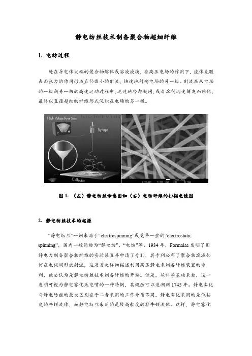
静电纺丝技术制备聚合物超细纤维1.电纺过程处在导电体尖端的聚合物熔体或溶液液滴,在高压电场的作用下,流体克服表面张力的作用形成直径微小的射流,快速地射向电场的另一极。
射流在从电场的一极向另一极的高速运动过程中,迅速地冷却凝固,或者溶剂迅速挥发而固化,最终以直径超细的纤维形式沉积在电场的另一极。
图1. (左)静电纺丝示意图和(右)电纺纤维的扫描电镜图2.静电纺丝技术的起源“静电纺丝”一词来源于“electrospinning”或更早一些的“electrostatic spinning”,国内一般简称为“静电纺”、“电纺”等。
1934年,Formalas发明了用静电力制备聚合物纤维的实验装置并申请了专利,其专利公布了聚合物溶液如何在电极间形成射流,这是首次详细描述利用高压静电来制备纤维装置的专利,被公认为是静电纺丝技术制备纤维的开端。
但是,从科学基础来看,这一发明可视为静电雾化或电喷的一种特例,其概念可以追溯到1745年。
静电雾化与静电纺丝的最大区别在于二者采用的工作介质不同,静电雾化采用的是低粘度的牛顿流体,而静电纺丝采用的是较高粘度的非牛顿流体。
这样,静电雾化技术的研究也为静电纺丝体系提供了一定的理论依据和基础。
对静电纺丝过程的深入研究涉及到静电学、电流体力学、流变学、空气动力学等领域。
20世纪30年代到80年代期间,静电纺丝技术发展较为缓慢,科研人员大多集中在静电纺丝装置的研究上,发布了一系列的专利,但是尚未引起广泛的关注。
进入90年代,美国阿克隆大学Reneker研究小组对静电纺丝工艺和应用展开了深入和广泛的研究。
特别是近年来,随着纳米技术的发展,静电纺丝技术获得了快速发展,世界各国的科研界和工业界都对此技术表现出了极大的兴趣。
此段时期,静电纺丝技术的发展大致经历了四个阶段:1)第一阶段主要研究不同聚合物的可纺性和纺丝过程中工艺参数对纤维直径及性能的影响以及工艺参数的优化等;2)第二阶段主要研究静电纺纳米纤维成分的多样化及结构的精细调控;3)第三个阶段主要研究静电纺纤维在能源、环境、生物医学、光电等领域的应用;4)第四阶段主要研究静电纺纤维的批量化制造问题。
静电纺丝技术静电纺丝技术是利用高压静电作用使聚合物溶液或熔体带电并发生形变,在喷头末端处形成悬垂的锥状液滴,当液滴表面静电斥力大于其表面张力时,液滴表面就会喷射出高速飞行的射流,并在较短的时间内经电场力拉伸、溶剂挥发、聚合物固化形成纤维。
所获得的静电纺纤维直径小、比表面积大,同时纤维膜还具有孔径小、孔隙率高、孔道连通性好等优势,在过滤、传感、医疗卫生以及自清洁等领域具有广泛的应用。
1静电纺丝的起源与发展静电纺丝起源于200多年前人们对静电雾化过程的研究。
1745年,Bose通过对毛细管末端的水表面施加高电势,发现其表面将会有微细射流喷出,从而形成高度分散的气溶胶,并得出该现象是由液体表面的机械压力与电场力失衡所引起的。
1882年,Rayleigh指出当带电液滴表面的电荷斥力超过其表面张力时,就会在其表面形成微小的射流,并对该现象进行理论分析总结,得到射流形成的临界条件。
1902年,Cooley与Morton申请了第一个利用电荷对不同挥发性液体进行分散的专利。
随后Zeleny研究了毛细管端口处液体在高压静电作用下的分裂现象,通过观察总结出几种不同的射流形成模型,认为当液滴内压力与外界施加压力相等时,液滴将处于不稳定状态。
基于上述的基础研究,1929年,Hagiwara公开了一种以人造蚕丝胶体溶液为原料,通过高压静电制备人造蚕丝的专利。
1934年,Formhals设计了一种利用静电斥力来生产聚合物纤维的装置并申请了专利,该专利首次详细介绍了聚合物在高压电场作用下形成射流的原因,这被认为是静电纺丝技术制备纤维的开端。
从此,静电纺丝技术成为了一种制备超细纤维的有效可行方法。
1966年,Simons发明了一种生产静电纺纤维的装置,获得了具有不同堆积形态的纤维膜。
20世纪60年代,Taylor在研究电场力诱导液滴分裂的过程中发现,随着电压升高,带电液体会在毛细管末端逐渐形成一个半球形状的悬垂液滴,当液滴表面电荷斥力与聚合物溶液表面张力达到平衡时,带电液滴会变成圆锥形;当电荷斥力超过表面张力时,就会从圆锥形聚合物液滴表面喷射出液体射流。
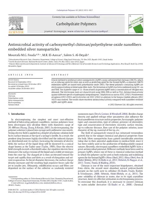
Carbohydrate Polymers 92 (2013) 1012–1017Contents lists available at SciVerse ScienceDirectCarbohydratePolymersj o u r n a l h o m e p a g e :w w w.e l s e v i e r.c o m /l o c a t e /c a r b p olAntimicrobial activity of carboxymethyl chitosan/polyethylene oxide nanofibers embedded silver nanoparticlesMoustafa M.G.Fouda a ,b ,∗,M.R.El-Aassar c ,Salem S.Al-Deyab aaPetrochemical Research Chair,Chemistry Department,College of Science,King Saud University,P.O.Box 2455,Riyadh 11451,Saudi Arabia bTextile Research Division,National Research Center,Dokki,Cairo,P.O.Box 12622,Giza 12522,Egypt cPolymer Materials Research Department,Institute of Advanced Technology and New Material,City of Scientific Research and Technology Applications,New Borg El-Arab City 21934,Alexandria,Egypta r t i c l ei n f oArticle history:Received 22September 2012Received in revised form 10October 2012Accepted 19October 2012Available online 26 October 2012Keywords:ChitosanPolyethylene oxide Silver nanoparticles Electrospinning Antimicrobiala b s t r a c tA facile method to synthesize silver nanoparticles (AgNPs)using carboxymethyl chitosan (CMCTS),which act as reducing agent for silver ions as well as protecting agent for the formed AgNPs,is reported.CMCTS embedded AgNPs are mixed with polyethylene oxide (PEO).The blend polymers containing AgNPs are electrospun resulting in blend nano-fiber mats.The formation of AgNPs has been confirmed using UV–vis and TEM.The diameter range of 12–18nm of well-dispersed AgNPs with a concentration of 100ppm was obtained.The electrospun mats are characterized using SEM,EDX as well as TGA.Antimicrobial activity against different species of pathogenic/nonpathogenic;Staphylococcus aureus ATCC 25923,Pseudomonas aeruginosa ATCC 27853and Escherichia coli ATCC 25922in addition to the fungus Candida albicans ATCC 10231was studied.The results show excellent antimicrobial activity compared with nanofibers without AgNPs and AgNPs alone.© 2012 Elsevier Ltd. All rights reserved.1.IntroductionIn electrospinning,the simplest and most cost-effective method of fabricating polymer nanofibres,various polymers have been electrospun into ultrafine fibers with diameters range of 20–400nm (Huang,Zhang,&Kotaki,2003).In electrospinning,the polymer solution is placed into syringe with millimeter size nozzle.Strong electric field is applied on a droplet of polymer solution held by its surface tension at the tip of a syringe’s needle.As a result,the pendent drop becomes highly electrified and the induced charges are distributed over its surface.Increasing the intensity of electric field,the surface of the liquid drop will be distorted to a conical shape known as the Taylor cone (Taylor,1969).Once the electric field strength exceeds a threshold value,the repulsive electric force dominates the surface tension of the liquid and a stable jet emerges from the cone tip.The charged jet is then accelerated toward the target and rapidly thins and dries as a result of elongation and sol-vent evaporation.As the jet diameter decreases,the surface charge density increases and the resulting high repulsive forces split the jet to smaller jets.Ultimately,solidification occurs and fibers are deposited on the surface of the collector as randomly oriented∗Corresponding author at:Petrochemical Research Chair,Chemistry Department,College of Science,King Saud University,P.O.Box 2455,Riyadh 11451,Saudi Arabia.E-mail addresses:m gaballa@ ,mmfoudah@.sa (M.M.G.Fouda).nonwoven mats (Derch,Greiner,&Wendorff,2004).Besides charge density and applied voltage other parameters also influence the final nanofibrous structure and its properties,for example:polymer types and concentration,type of solvent,presence of electrolyte,type and concentration of electrolyte,viscosity,surface tension,tip-to-collector distance,flow rate of the polymer solution,inner diameter of the tip,material of the tip,etc.The field of nanoparticle research has witnessed tremendous growth due to the unique chemical and physical properties from the bulk.Silver nanoparticles have gained considerable attention today due to their potential applications in medical field,since it has been widely used in the production of biodegradable surgical sutures.Recently,electrospun nanofibers embedded AgNPs have a great antimicrobial potential.Different methods have been used to prepare AgNPs,where one of these is chemical reduction method in which the polymer can be used as both reducing and stabilizing agents for the formed AgNPs (Abou-Okeil,2012;Abou-Okeil,Amr,&Abdel-Mohdy,2012;El-Rafie et al.,2011;Hebeish,El-Naggar,et al.,2011;Textor,Fouda,&Mahltig,2010).Chitosan is one of the most important biopolymers,obtained from chitin,the second most abundant natural polysaccharide present on the earth next to cellulose (El-Shafei,Fouda,Knittel,&Schollmeyer,2008;Hebeish,Abdel-Mohdy,et al.,2011).The poor solubility of chitosan in water,due to its rigid crystalline structure,limits its effective utilization in electrospinning process.To overcome this drawback,it is necessary to convert chitosan to water-soluble derivative (El-Shafei et al.,2008).Chemical0144-8617/$–see front matter © 2012 Elsevier Ltd. All rights reserved./10.1016/j.carbpol.2012.10.047M.M.G.Fouda et al./Carbohydrate Polymers92 (2013) 1012–10171013Fig.1.Schematic diagram of the typical electrospinning setup.modification is anticipated to be quite promising.Carboxymethy-lation is one of the chemical methods to prepare water-soluble chi-tosan.This reaction takes place preferentially either at C-6hydroxyl groups or at the NH2-group resulting in N/O–carboxymethyl chi-tosan(CMCTS).Both products are water-soluble and contain an amino group either as the primary(NH2)or as secondary amine (NH CH2COOH).Polyethylene oxide(PEO)is one of the few biodegradable syn-thetic polymers approved for internal use in food,cosmetics, personal care products,and pharmaceutical.PEO is an effective ion conductive polymer(Morgado et al.,1999).Therefore,it is added in order to enhance the spinnability of the modified natural polymer.The objective of this research work is to synthesize well-stabilized AgNPs using CMCTS followed by electrospinning of CMCTS–AgNPs/PEO solution.The structure,morphology and the antimicrobial activity of the resulted nanofiber mats are character-ized.2.Experimental2.1.MaterialsPolyethylene oxide(PEO)(≥95%,average Mw124–186kg/mol) was obtained from Scientific Polymer Products,Inc.Silver nitrate (AgNO3)(99.998%)was purchased from Aldrich,Germany.Chi-tosan,DDA95%was obtained from Aldrich Chemical Co.,Germany. All other solvents and reagents were used as received without any further purification.2.2.Synthesis of carboxymethyl chitosan(CMCTS)The experimental technique adopted for carboxymethylation of chitosan was as follows:certain volume of sodium hydroxide solution(30%,w/v)was added to16g chitosan suspended in iso-propyl alcohol.The mixture was left under stirring for30min at room temperature.To this mixture34g of monochloroacetic acid was added and the content of theflask was subjected to continuous stirring for3h.At the end,the excess alkali was neutralized using glacial acetic acid and chitosan was precipitated by adding acetone. Finally,modified chitosan wasfiltered and washed with isopropyl alcohol/water(70:30)several times and dried at60◦C(El-Shafei et al.,2008).Thefinal product was soluble in water.2.3.Synthesis of silver nanoparticles(AgNPs)Silver nanoparticles(AgNPs)were prepared according to the procedure described by El-Rafie et al.(2011)and can be summa-rized as follows:0.5g of CMCTS is dissolved in100ml of distilled water,the temperature of the reaction is raised to60◦C and the pH is adjusted to11.5by using10M NaOH.1ml of AgNO3(1.7M) is added dropwise to the previous solution under continuous stir-ring for almost1h.The formation of silver nanoparticles solution was observed by monitoring the color change(visually,when the color of the solution started to change from its original color to the different degrees of the yellow color,then the reduction reac-tion started to work and silver nanoparticles started to seed).The AgNPs formed are characterized by(UV–vis),transmission electron microscope(TEM).2.4.Electrospinning of CMCTS–AgNPs/PEO solution2g of CMCTS is added to CMCTS solution containing sil-ver nanoparticles(0.5wt%)while stirring.To this solution,PEO (5wt%)is added slowly under continuous stirring till homogeneity occurs.Electrospinning of the prepared blend polymers solution containing AgNPs was carried out using two different methods; typical electrospinning technique and Nanospider technology as a modified electrospinning technique.A schematic diagram of the complete electrospinning apparatus is shown in Fig.1.It consisted of a syringe and stainless needle,a grounded electrode,an iron plate covered by aluminum foil as a collector,and an adjustable high voltage supply.2.5.Testing and analysisUV–vis spectrum was used to prove the formation of AgNPs (Hebeish,El-Naggar,et al.,2011).Particle shapes and sizes of AgNPs were obtained by transmission electron microscope(TEM); JEOL-JEM-1230.Scanning electron microscope(SEM)(JEOL GSM-6610LV)and(JEOL GSM-7600F)field emission scanning electron microscope were used to study the surface characteristics of elec-trospun nanofibers.Specimen in the form offilms was mounted on the specimen stabs and coated with thinfilm of gold by the sputtering method.The micrograph was taken at magnifica-tion of1000×using(KV)accelerating voltage.FT-IR spectra were obtained using FT-IR spectrometer,Bruker,TENSOR Series FT-IR1014M.M.G.Fouda et al./Carbohydrate Polymers 92 (2013) 1012–1017Fig.2.Solid state 13C NMR spectrum typical for O -carboxymethyl chitosan.Spectrometer,Germany,connected to a PC,and the data were analyzed by IR Solution software,where analytical methods are standard in OPUS TM software.2.6.Antimicrobial evaluation of electrospun nanofibersIn order to evaluate the antimicrobial properties of electrospun nanofiber mats with/without AgNPs against microbial pathogens and to compare this effect with the commonly used antibiotics in addition to AgNPs alone as +ve control,the zone of inhibition test was performed against the gram positive bacterium Staphylococ-cus aureus ATCC 25923,the gram negative bacteria Pseudomonas aeruginosa ATCC 27853and Escherichia coli ATCC 25922in addi-tion to the fungus Candida albicans ATCC 10231.To perform the test,several colonies of each strain,obtained from a fresh cul-ture in blood agar plate,were suspended in 5ml of Mueller-Hinton broth to achieve turbidity equal to the 0.5Mac-Farland standards.The suspensions were inoculated with sterile swabs onto 150mm diameter Mueller-Hinton agar plates and after the agar surfaces were allowed to dry,tested disks were applied on each plate.Plates were incubated at 37◦C for 24h and the zones of inhibition (IZ)were measured.Same was performed for the Candida except that it was inoculated in Sabouraud dextrose agar medium and incu-bated for 2–3days at 37◦C.The antimicrobial agents tested in this study were CMCTS–PEO nano-fiber incorporated with silver nano-particles (CMCTS–AgNPs/PEO),the antibiotic Amikacin (AK),ampicillin/clavulinic acid (AMC),100ppm AgNPs solution (10L per disk)as a positive control,in addition to negative controls as empty disks of CMCTS–PEO nano-fibers.3.Results and discussion3.1.Characterization of (CMCTS)by solid state 13C NMRCarboxymethylation of chitosan (CTS)is achieved with monochloroacetic acid and sodium hydroxide.According to El-Shafei et al.(2008)this reaction takes place preferentially either at C-6hydroxyl groups or at the NH 2-group resulting in N/O–carboxymethyl chitosan (CMCTS).The solid state 13C NMR spectrum for a typical N-carboxymethyl chitosan shows sig-nals attributed to the N-carboxymethyl substituent,at 47.7and 168.7ppm,for N CH 2and COOH,respectively (El-Shafei et al.,2008).But in case of our results,the solid state 13C NMR described in Fig.2shows signals at 73and 175ppm which attributed to O CH 2and COOH respectively.This downfield shift of thecarbon indicates the formation of O -carboxymethyl chitosan.The formation of this product agrees with the higher reactivity of hydroxyl group of C 6in this heterogeneous reaction.The N -carboxymethyl substituent is not present because of the absence of peaks at 47and 168ppm for N CH 2and COOH respectively.3.2.Characterization of the synthesized silver nanoparticles (AgNPs)In this research work,CMCTS was used as reducing and as stabi-lizing agent too.The formation of AgNPs could be visualized from changes in the color of the solutions from colorless to light yellow.The reduction of Ag +could occur via the reduction effect of CMCTS at 60◦C and pH 11.5for 30min.Fig.3shows the UV–visible absorp-tion spectra of AgNPs.The surface plasmon absorption bands are centered around 409nm (El-Rafie et al.,2011).The absorption band at 405nm becomes stronger and narrower which means higher conversion of Ag +to Ag 0with smaller nanoparticles size.Fig.4a and b shows the TEM image and the histogram of the size and size distribution of the AgNPs.Results revealed that the size range of prepared AgNPs was between 12and 18nm.3.3.Morphology of the CMCTS–AgNPs/PEO-electrospun nanofibersThe performance and morphology of the electrospun fiber were affected by the electrospinning process parameters.In the present study,two different electrospinning setups were used.In the first setup,a typical electrospinning setup was used (Fig.1)alongwithFig.3.UV–vis spectra of silver nanoparticles embedded in CMCTS.M.M.G.Fouda et al./Carbohydrate Polymers92 (2013) 1012–10171015Fig.4.(a and b)TEM image and the histogram of the size and size distribution of the AgNPs.Nanospider technology.Both electrospinning setup and Nanospi-der are used in order to prepare nanofiber mats,but,Nanospider is used in large scale/sample production of the selected and best nanofiber mats from the results obtained,in addition,no differ-ence in morphology of the resulted mats for both techniques is observed.Generally,the electrospun mat is opaque due to light scattering from thefibrous structure.The obtainedfibers(Fig.5a and b)had cylindrical morphology and nofiber bundles,indicat-ing that applied parameters were adequate for the formation of fibers and proper evaporation of the solvent.On the other hand, the presence of AgNPs in CMCTS has little effect on the electrospun fiber morphology.Thefiber diameter ranged from50to300nm. In addition,after the encapsulation of AgNPs into CMCTS–PEO nanofiber,thefiber diameter decreases compared tofibers consist-ing of CMCTS–PEO without AgNPs,due to the high conductivity, which plays a key role in decreasing of thefiber diameter during electrospinning(Sheikh et al.,2010).The presence of AgNPs results in high electric charge and subsequently high conductivity of the polymer solution which leads to high charge values during elec-trospinning process and possibly forming thinnerfiber diameter (Nirmala et al.,2010;Nirmala,Navamathavan,Kang,El-Newehy, &Kim,2011;Nirmala,Park,et al.,2011).At the same timethe Fig.5.SEM images of electrospun nanofibers containing AgNPs;(a)CMCTS;(b)CMCTS–Ag,(c)CMCTS/PEO–Ag and(d)CMCTS/PEO–Ag(EDX).1016M.M.G.Fouda et al./Carbohydrate Polymers 92 (2013) 1012–1017Fig.6.FT-IR spectra of electrospun nanofibers;(a)PEO and (b)PEO–AgNPs.fibrous structure assures much more loading of AgNPs into the fibers.EDX was used to analyze the elemental constitution of solid samples.Elementary analysis of CMCTS–PEO/silver nanocompos-ite was carried out by using SEM–EDX.Fig.5c displays a spectrum of CMCTS–PEO/silver nanocomposite obtained by elemental micro-probe analysis of EDX.The results show that carbon,oxygen,and Ag were the principal element of CMCTS–PEO/silver nanocomposite.EDX analysis,as a result,provides direct evidence that AgNPs are embedded in the CMCTS–PEO composite.The quantitative analysis of CMCTS–PEO/silver nanocomposite is presented in Table 1.At the same time,Fig.5a and b shows SEM images of CMCTS–PEO/AgNPs nanofibers,which revealed that the AgNPs were evenly distributed in the CMCTS–PEO ultrafine fibers with an average size less than 12–18nm.This suggested that the AgNPs were well stabilized by CMCTS during the preparation of AgNPs.Table 1Stoichiometric ratio of CMCTS–AgNPs.ElementWeight%Atomic%(PEO)/Ag C K 83.9088.17O K 14.8111.68Ag L1.290.15Total100.003.4.FT-IR spectra of electrospun nanofibersFT-IR spectra of electrospun CMCTS–PEO and CMCTS–AgNPs/PEO are shown in Fig.6.The frequencies and assignments for the pristine PEO are indicated asfollows:Fig.7.Diameter inhibition zone (cm)of electrospun nanofibers against Staphylococcus aureus (Sa),Pseudomonas aeruginosa (ps)and Escherichia coli (Ec).M.M.G.Fouda et al./Carbohydrate Polymers92 (2013) 1012–101710172882cm−1due to the CH2group stretching vibration,1097cm−1 and841cm−1due to the C O C asymmetric stretch and bending vibrations.On the other hand,for the electrospun CMCTS–AgNPs nanofiber shows the same characteristic bands,in which the intensity of the bands at2882cm−1and at841cm−1was increased due to the CH2and C O C stretching vibration upon the presence of AgNPs.3.5.Antimicrobial of electrospun nanofibersFig.7shows chart of inhibition zone of the tested antimicrobial samples and the corresponding plates(a,b,c).Results illustrated that S.aureus was the most sensitive microbe against antimicro-bial disk(AMC),CMCTS–PEO–AgNPs nanofiber,and AgNPs solution with inhibition zone30,22and15millimeters(mm)respectively.C.albicans was the least sensitive against all tested antimicrobial agents with IZ of0mm,except for CMCTS–PEO–AgNPs that showed IZ of12mm.It was found that the CMCTS–PEO–AgNPs nanofibers were the most effective silver containing material with IZs of20, 18,15and12against S.aureus,P.aeruginosa,E.coli and C.albicans, respectively.In contrast,the AgNPs showed the least antimicro-bial activity among silver containing nanofibers with IZ of13,7, 6and0mm against S.aureus,P.aeruginosa,E.coli and C.albicans, respectively.It was observed that CMCTS–PEO–AgNPs nanofibers are the most effective silver containing material against all tested microbes.Also,it was found that CMCTS–PEO–AgNPs nanofiber was more than twofold strength of the positive control(AgNPs).How-ever,its efficacy was less than any of the tested antibiotics,but this can be compensated with the less hazardous effect of antibi-otics and the less chance of resistance development compared with silver nanoparticles.4.ConclusionSilver nanoparticles(AgNPs)have been successfully prepared using carboxymethyl chitosan(CMCTS)which acts as both reduc-ing and stabilizing agent for the formed AgNPs.CMCTS–AgNPs with polyethylene oxide(PEO)are well mixed together and subjected to electrospinning process.The resulted nanofiber mats’embedded AgNPs are characterized using different analytical tools.The pres-ence of silver ions in the polymer structure was found to be strongly affecting the electrospun nanofibers diameters due to enhance-ment of electrical conductivity of the nanofibers.The obtained results indicated that the number of Ag+ions that were converted into Ag0increased with increasing the aging time.Antimicrobial activity of the prepared sample was evaluated against different types of microorganisms.It was observed that CMCTS–PEO–AgNPs nanofibers are the most effective silver containing material against all tested microbes.Also,it was found that CMCTS–PEO–AgNPs nanofiber was more than twofold strength of the positive con-trol(AgNPs).Finally,the prepared CMCTS–AgNPs/PEO nanofibers matrix could be properly employed as recommended candidate for many biological applications such as prolonged antimicrobial wound dressing materials.AcknowledgementThe authors extend their appreciation to the Deanship of Scien-tific Research at King Saud University for funding this work through research group no.RGP-VPP-201.ReferencesAbou-Okeil,A.(2012).Ag nanoparticles growing onto cotton fabric using chitosan as a template.Journal of Natural Fibers,9,61–72.Abou-Okeil,A.,Amr,A.,&Abdel-Mohdy,F.A.(2012).Investigation of silver nanopar-ticles synthesis using aminated-beta-cyclodextrin.Carbohydrate Polymers,89, 1–6.Derch,R.,Greiner,A.,&Wendorff,J.H.(Eds.).(2004).Polymer nanofibers prepared by electrospinning.Dekker encyclopedia of nanoscience and nanotechnology.New York:CRC.El-Rafie,M.H.,El-Naggar,M.E.,Ramadan,M.A.,Fouda,M.M.G.,Al-Deyab,S.S., &Hebeish,A.(2011).Environmental synthesis of silver nanoparticles using hydroxypropyl starch and their characterization.Carbohydrate Polymers,86(2), 630–635.El-Shafei,A.M.,Fouda,M.M.G.,Knittel,D.,&Schollmeyer,E.(2008).Antibacte-rial activity of cationically modified cotton fabric with carboxymethyl chitosan.Journal of Applied Polymer Science,110(3),1289–1296.Hebeish,A.,Abdel-Mohdy,F.A.,Fouda,M.M.G.,Elsaid,Z.,Essam,S.,Tammam,G.H.,et al.(2011).Green synthesis of easy care and antimicrobial cotton fabrics.Carbohydrate Polymers,86(4),1684–1691.Hebeish,A.,El-Naggar,M.E.,Fouda,M.M.G.,Ramadan,M.A.,Al-Deyab,S.S.,& El-Rafie,M.H.(2011).Highly effective antibacterial textiles containing green synthesized silver nanoparticles.Carbohydrate Polymers,86(2),936–940. Huang,Z.M.,Zhang,Y.Z.,&Kotaki,M.(2003).A review on polymer nanofibers by electrospinning and their applications in posites Science and Technology,63(15),2223–2253.Morgado,J.,Friend,R.H.,Cacialli,F.,Chuah,B.S.,Moratti,S.C.,&Holmes,A.B.(1999).Journal of Applied Physics,86,6392.Nirmala,R.,Nam,K.T.,Park,S.J.,Shin,Y.S.,Navamathavan,R.,&Kim,H.Y.(2010).Formation of high aspect ratio polyamide-6nanofibers via electrically induced double layer during electrospinning.Applied Surface Science,256,6318–6323. Nirmala,R.,Navamathavan,R.,Kang,H.-S.,El-Newehy,M.H.,&Kim,H.Y.(2011).Preparation of polyamide-6/chitosan composite nanofibers by a single solvent system via electrospinning for biomedical applications.Colloids and Surfaces B: Biointerfaces,83,173–178.Nirmala,R.,Park,H.-M.,Navamathavan,R.,Kang,H.-S.,El-Newehy,M.H.,&Kim,H.Y.(2011).Lecithin blended polyamide-6high aspect ratio nanofibers scaf-folds via electrospinning for human osteoblast cell culture.Materials Science and Engineering C,31,486–493.Sheikh, F. A.,Barakat,N. A.M.,Kanjwal,M. A.,Jeon,S.H.,Kang,H.S.,& Kim,H.Y.(2010).Self synthesize of silver nanoparticles in/on polyurethane nanofibers:Nano-biotechnological approach.Journal of Applied Polymer Science, 115,3189–3198.Taylor,G.I.(1969).Proceedings of the Royal Society of London,313,453.Textor,T.,Fouda,M.M.G.,&Mahltig,B.(2010).Deposition of durable thin silver layers onto polyamides employing a heterogeneous Tollens’reaction.Applied Surface Science,256(8),2337–2342.。

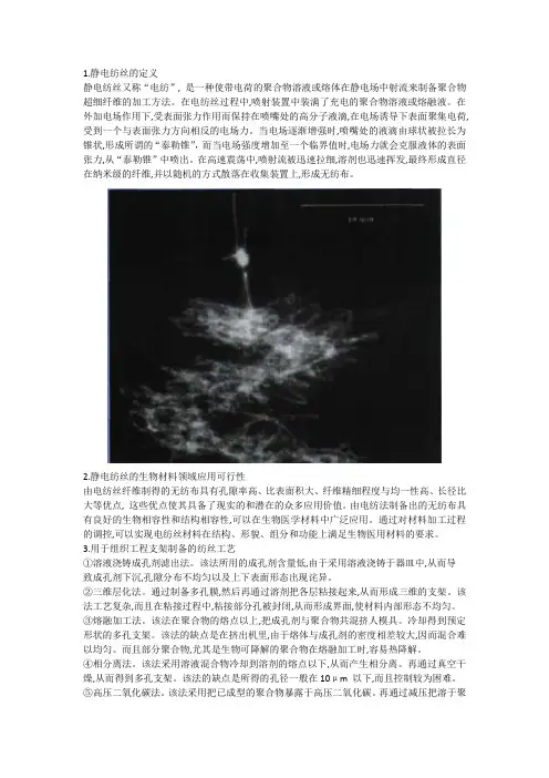
1.静电纺丝的定义静电纺丝又称“电纺”, 是一种使带电荷的聚合物溶液或熔体在静电场中射流来制备聚合物超细纤维的加工方法。
在电纺丝过程中,喷射装置中装满了充电的聚合物溶液或熔融液。
在外加电场作用下,受表面张力作用而保持在喷嘴处的高分子液滴,在电场诱导下表面聚集电荷, 受到一个与表面张力方向相反的电场力。
当电场逐渐增强时,喷嘴处的液滴由球状被拉长为锥状,形成所谓的“泰勒锥”,而当电场强度增加至一个临界值时,电场力就会克服液体的表面张力,从“泰勒锥”中喷出。
在高速震荡中,喷射流被迅速拉细,溶剂也迅速挥发,最终形成直径在纳米级的纤维,并以随机的方式散落在收集装置上,形成无纺布。
2.静电纺丝的生物材料领域应用可行性由电纺丝纤维制得的无纺布具有孔隙率高、比表面积大、纤维精细程度与均一性高、长径比大等优点, 这些优点使其具备了现实的和潜在的众多应用价值。
由电纺法制备出的无纺布具有良好的生物相容性和结构相容性,可以在生物医学材料中广泛应用。
通过对材料加工过程的调控,可以实现电纺丝材料在结构、形貌、组分和功能上满足生物医用材料的要求。
3.用于组织工程支架制备的纺丝工艺①溶液浇铸成孔剂滤出法。
该法所用的成孔剂含量低,由于采用溶液浇铸于器皿中,从而导致成孔剂下沉,孔隙分布不均匀以及上下表面形态出现诧异。
②三维层化法。
通过制备多孔膜,然后再通过溶剂把各层粘接起来,从而形成三维的支架。
该法工艺复杂,而且在粘接过程中,粘接部分孔被封闭,从而形成界面,使材料内部形态不均匀。
③熔融加工法。
该法在聚合物的熔点以上,把成孔剂与聚合物共混挤人模具。
冷却得到预定形状的多孔支架。
该法的缺点是在挤出机里,由于熔体与成孔剂的密度相差较大,因而混合难以均匀。
而且部分聚合物,尤其是生物可降解的聚合物在熔融加工时,容易热降解。
④相分离法。
该法采用溶液混合物冷却到溶剂的熔点以下,从而产生相分离。
再通过真空干燥,从而得到多孔支架。
该法的缺点是所得的孔径一般在10μm 以下,而且控制较为困难。

第1篇一、实验目的1. 熟悉静电纺丝法的原理和操作步骤。
2. 掌握利用静电纺丝法制备纳米纤维的方法。
3. 分析不同参数对纳米纤维形态和性能的影响。
二、实验原理静电纺丝法是一种常用的制备纳米纤维的技术,利用高压电场使高分子溶液或熔体在喷丝头处形成细小的液滴,液滴在电场力、表面张力以及惯性力的共同作用下,拉伸形成纳米纤维。
通过控制实验参数,可以制备出具有不同直径、形态和性能的纳米纤维。
三、实验材料与设备材料:1. 聚乙烯醇(PVA)粉末2. 乙醇3. 纳米氧化锌(ZnO)设备:1. 静电纺丝机2. 电子天平3. 真空干燥箱4. 扫描电子显微镜(SEM)5. 透射电子显微镜(TEM)6. X射线衍射仪(XRD)四、实验步骤1. 配制PVA溶液:称取一定量的PVA粉末,加入适量乙醇溶解,搅拌均匀。
2. 配制纳米氧化锌溶液:称取一定量的纳米氧化锌,加入适量乙醇溶解,搅拌均匀。
3. 混合溶液:将PVA溶液和纳米氧化锌溶液按照一定比例混合均匀。
4. 静电纺丝:将混合溶液注入静电纺丝机,设置合适的电压、喷头与收集器距离等参数,进行静电纺丝。
5. 收集纳米纤维:将静电纺丝制备的纳米纤维收集在铝箔上,干燥。
6. 纳米纤维表征:利用SEM、TEM、XRD等手段对纳米纤维进行表征。
五、实验结果与分析1. SEM分析:从SEM图像可以看出,纳米纤维呈细长条状,直径在100-200nm之间,表面光滑。
2. TEM分析:从TEM图像可以看出,纳米纤维具有明显的纳米级特征,直径在30-50nm之间。
3. XRD分析:从XRD图谱可以看出,纳米纤维具有较好的结晶度,表明纳米氧化锌在纳米纤维中均匀分散。
六、讨论1. 实验结果表明,通过静电纺丝法制备的纳米纤维具有较好的结晶度和均匀的分散性,表明纳米氧化锌在纳米纤维中均匀分散。
2. 实验过程中,电压、喷头与收集器距离等参数对纳米纤维的直径和形态有较大影响。
适当提高电压和缩短喷头与收集器距离,可以制备出更细、更均匀的纳米纤维。

静电纺丝工艺
一、溶液制备
静电纺丝工艺的第一步是制备纺丝溶液。
这一过程涉及到将聚合物溶解在适当的溶剂中,形成均一的溶液。
为了获得最佳的纺丝效果,需要控制溶液的粘度、浓度以及溶剂的蒸发速率。
通常,聚合物在溶剂中的溶解度越高,溶液的粘度越低,越有利于纺丝。
二、静电纺丝
在制备好纺丝溶液后,通过静电纺丝设备进行纺丝。
静电纺丝过程中,高压电场施加在喷嘴和收集器之间,使得溶液形成细流并射出。
在电场的作用下,细流会逐渐拉伸、细化,最终形成纤维。
这一过程中,可以通过调整电场强度、溶液流量以及喷嘴到收集器的距离等参数来控制纤维的形貌和直径。
三、收集与处理
纺出的纤维会落在收集器上,形成非织造布状的纤维膜。
为了获得实用的纤维材料,通常需要对收集到的纤维进行后处理。
这包括洗涤以去除残留的溶剂和杂质,以及热处理或化学处理以改善纤维的性能。
四、应用与性能测试
静电纺丝工艺制备的纤维材料在许多领域都有广泛的应用,如过滤、增强、生物医学等。
对于不同的应用,纤维材料的性能要求也不同。
因此,需要对制备的纤维材料进行性能测试,以满足实际需求。
常见的性能测试包括纤维直径、形貌、力学性能、热性能、电性能等。
总之,静电纺丝工艺是一种简单、环保的制备纤维材料的方法。
通过合理的工艺参数选择和控制,可以制备出具有优异性能的纤维材料,满足各种应用需求。
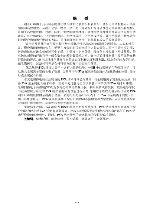
摘要纳米纤维由于具有极小的直径以及极大比表面积和表面积~体积比的结构特点,其表面能和活性增大,从而在化学、物理(热、光、电磁等)等许多性能方面表现出特异性,可用于高性能吸附、过滤、防护、生物医用等材料。
聚合物纳米纤维的制备方法有静电纺丝法、复合纺丝法、分子喷丝板法、生物合成法、化学合成法等,静电纺丝是一种高效低耗的聚合物纳米纤维制备方法,是目前研究的热点,而且具有较大的发展前景。
静电纺丝是基于高压静电场下导电流体产生高速喷射的原理发展而来,其基本过程是:聚合物溶液或熔体在几千至几万伏的高压静电场下克服表面张力而产生带电喷射流,溶液或熔体射流在喷射过程中干燥,并保持一定电荷量,最终落在接收极上形成纤维。
静电纺丝制得的纤维直径一般在数十纳米到数微米之间。
静电纺的纤维制品主要呈无纺布状纤维毡的形式,静电纺纤维毡具有很高的比表面积和表面积体积比,以及良好的力学性能,在生物医学、过滤材料和复合材料等方面有广阔的应用前景。
聚乙烯醇(PV A)纤维大分子中含有大量的羟基,—OH中的氧原子含有孤对电子,可以进入金属离子空的价电子轨道,金属离子与PV A配位体通过杂化轨道形成配位键,进而形成金属配合纤维。
本文选用静电纺丝法制备的PV A纳米纤维毡为基体,与金属铜离子发生配位反应,制备PV A基金属配合纳米纤维.实验中通过静电纺丝法制备不同浓度的PV A纳米纤维膜,采用扫描电子显微镜(SEM)观察电纺纤维的微观形貌,利用旋转式粘度仪、数显电导率仪与液滴性状分析仪对PV A纺丝液的流变性能进行研究,采用原子吸收光谱分析仪研究PV A 纳米纤维膜吸附的金属离子含量,采用红外光谱(FT-IR)分析了PV A与金属离子的配合作用。
同时也测定了PV A及其金属离子配合纤维的动态接触角和力学性能,以研究金属配合对纳米纤维导电性、亲水性和力学性能的影响。
实验结果表明,PV A浓度为10%的静电纺纳米纤维最佳;PV A纳米纤维与金属离子配合的能力较常规PV A纤维有显著提高。
静电纺丝1原理静电纺丝是一种特殊的纤维制造工艺,聚合物溶液或熔体在强电场中进行喷射纺丝。
在电场作用下,针头处的液滴会由球形变为圆锥形(即“泰勒锥”),并从圆锥尖端延展得到纤维细丝。
这种方式可以生产出纳米级直径的聚合物细丝。
2静电纺丝影响因素1,聚合物的分子量,分子量分布和分子结构(分支,线性等)2,溶液性质(浓度,粘度,电导率,表面张力,液体流量等)3,电动势大小4,毛细管和收集屏幕之间的距离5,环境参数(温度,湿度和室内空气流速)6,收集装置的运动规律7,喷丝口针头形状3静电纺丝技术的发展静电纺丝技术的起源“静电纺丝”一词来源于“electrospinning”或更早一些的“electrostatic spinning”,国内一般简称为“静电纺”、“电纺”等。
1934年,Formalas发明了用静电力制备聚合物纤维的实验装置并申请了专利,其专利公布了聚合物溶液如何在电极间形成射流,这是首次详细描述利用高压静电来制备纤维装置的专利,被公认为是静电纺丝技术制备纤维的开端。
但是,从科学基础来看,这一发明可视为静电雾化或电喷的一种特例,其概念可以追溯到1745年。
静电雾化与静电纺丝的最大区别在于二者采用的工作介质不同,静电雾化采用的是低粘度的牛顿流体,而静电纺丝采用的是较高粘度的非牛顿流体。
这样,静电雾化技术的研究也为静电纺丝体系提供了一定的理论依据和基础。
对静电纺丝过程的深入研究涉及到静电学、电流体力学、流变学、空气动力学等领域。
20世纪30年代到80年代期间,静电纺丝技术发展较为缓慢,科研人员大多集中在静电纺丝装置的研究上,发布了一系列的专利,但是尚未引起广泛的关注。
进入90年代,美国阿克隆大学Reneker研究小组对静电纺丝工艺和应用展开了深入和广泛的研究。
特别是近年来,随着纳米技术的发展,静电纺丝技术获得了快速发展,世界各国的科研界和工业界都对此技术表现出了极大的兴趣。
此段时期,静电纺丝技术的发展大致经历了四个阶段:第一阶段主要研究不同聚合物的可纺性和纺丝过程中工艺参数对纤维直径及性能的影响以及工艺参数的优化等;第二阶段主要研究静电纺纳米纤维成分的多样化及结构的精细调控;第三个阶段主要研究静电纺纤维在能源、环境、生物医学、光电等领域的应用;第四阶段主要研究静电纺纤维的批量化制造问题。
静电纺丝法一、简介静电纺丝法是一种制备纳米级纤维的方法,也称为电纺法、电喷雾法。
该方法利用高压电场将聚合物液体或溶液中的高分子物质拉伸成极细的纤维,形成具有高比表面积和大孔隙度的纳米级材料。
静电纺丝法被广泛应用于生物医学、环境保护、能源储存等领域。
二、原理静电纺丝法基于高压电场作用下的毛细流动现象。
在高压电场作用下,聚合物液体或溶液中的高分子物质被拉伸成极细的纤维,并在空气中自由落体形成非常薄的纤维网。
这些纤维网具有非常大的比表面积和孔隙度,能够提供更多活性位点和更好的传质性能。
三、设备静电纺丝法主要包括以下设备:高压发生器、聚合物溶液输送系统、旋转收集器等。
其中,高压发生器是实现静电场作用下毛细流动现象必不可少的设备,聚合物溶液输送系统用于将聚合物液体或溶液输送到高压发生器中,旋转收集器用于收集纤维网。
四、操作步骤1. 准备聚合物溶液:将所需的聚合物溶解在适量的有机溶剂中,制备成所需浓度的聚合物溶液。
2. 调整高压发生器:根据聚合物溶液的性质和所需纤维尺寸调整高压发生器的参数。
3. 开始静电纺丝:将调整好的聚合物溶液输送到高压发生器中,启动高压发生器,使其产生静电场作用下毛细流动现象。
4. 收集纤维网:将旋转收集器放置在高压发生器下方,收集从高压发生器中产生的纤维网。
五、应用领域1. 生物医学:静电纺丝法可以制备出具有良好组织相容性和可控释放性能的纳米级支架材料,有望应用于组织工程、药物传递等领域。
2. 环境保护:静电纺丝法可以制备出具有高比表面积和孔隙度的纳米级吸附材料,用于处理水污染、空气污染等环境问题。
3. 能源储存:静电纺丝法可以制备出具有高比表面积和导电性能的纳米级电极材料,用于制备超级电容器、锂离子电池等能源储存器件。
六、优缺点1. 优点:静电纺丝法制备的纳米级材料具有高比表面积和孔隙度,能够提供更多活性位点和更好的传质性能;制备过程简单,操作易于掌握。
2. 缺点:静电纺丝法需要高压发生器作为设备支持,设备成本较高;由于聚合物溶液中的高分子物质容易受到氧化、水解等因素的影响,其稳定性较差。