微波传感器-CSD3技术说明书
- 格式:pdf
- 大小:125.48 KB
- 文档页数:2

版本变更记录版本号日期描述V1.0 2020年11月03日EG4003数据手册初稿目录1. 特性 (1)2. 描述 (1)3. 应用领域 (1)4. 引脚 (2)4.1 引脚定义 (2)4.2 引脚描述 (2)5. 结构框图 (3)6. 典型应用电路 (3)6.1 EG4003典型应用电路图 (3)6.2 EG4003控制继电器应用电路图 (4)6.3 EG4003可重复触发+光敏电阻应用电路图 (4)6.4 EG4003可重复触发+光敏电阻微波方案应用电路图 (5)7. 电气特性 (5)7.1 极限参数 (5)7.2 典型参数 (6)8. 应用设计 (7)8.1 振荡器工作频率计算 (7)8.2 触发延时时间定时器和触发封锁时间定时器 (7)8.3 A端重复和不可重复触发功能 (8)8.4 Vc触发禁止端 (8)8.5 第一级运放增益设定 (9)9. 封装尺寸 (10)9.1 SOP8封装尺寸 (10)9.2 DFN8封装尺寸 (11)EG4003芯片数据手册V1.01. 特性⏹8引脚微波、红外感应专用芯片,外围电路简单,成本低⏹静态功耗小,3V工作电源时功耗小于45uA, 5V工作电源时功耗小于75uA,非常适合电池供电系统应用⏹高输入阻抗运算放大器,可与多种传感器匹配,进行信号与处理⏹双向鉴幅器,可有效抑制干扰⏹内置参考电压,供内部比较器和运放的参考电压⏹内设延时时间定时器和封锁时间定时器,改变振荡器频率即可设定定时延时时间⏹外围元器件少,只需配置第一级运放的增益和振荡器的RC器件即能可靠工作⏹工作电源+3V~+6V⏹封装形式: SOP8、DFN82. 描述EG4003是一款专为微波、红外信号放大及处理输出的数模混合专用芯片,内部集成了运算放大器、双门限电压比较器、参考电压源、延时时间定时器和封锁时间定时器及状态控制器等,专用于防盗报警系统、人体门控制装置、照明控制开关等场合。
EG4003电源工作电压为+3V~+6V,采用 COMS工艺数模混合相结合的集成电路,8个引脚数封装设计,降低了外围电路元件数和整体成本,节省了PCB板空间。

OS100 SERIES Mini-Infrared Transmitter e-mail:**************For latest product manuals: Shop online at User’s G ui d e***********************Servicing North America:U.S.A. Omega Engineering, Inc.Headquarters: Toll-Free: 1-800-826-6342 (USA & Canada only)Customer Service: 1-800-622-2378 (USA & Canada only)Engineering Service: 1-800-872-9436 (USA & Canada only)Tel: (203) 359-1660 Fax: (203) 359-7700e-mail:**************For Other Locations Visit /worldwideThe information contained in this document is believed to be correct, but OMEGA accepts no liability for any errors it contains, and reserves the right to alter specifications without notice.Table of ContentsSection ...................................................................PageSafety Warnings and IEC Symbols (iii)Caution and Safety Information (iii)Section 1 Introduction ....................................................................1-1Section 2Installation ......................................................................1-12.1 Unpacking and Inspection ......................................1-12.2 Electrical Connection ..............................................2-1Section 3Operation ........................................................................3-13.1 Main Board ................................................................3-13.2 Ambient Temperature ..............................................3-23.3 Atmospheric Quality ................................................3-33.4 Measuring Temperature ..........................................3-33.5 Alarm Setting ............................................................3-43.6 Adding Extension Cable...........................................3-4Section 4 Laser Sight Accessory ...................................................4-14.1 Warning and Cautions .............................................4-14.2 Operating the Laser Sight Accessory .....................4-1Section 5 Specifications .................................................................5-15.1 General .......................................................................5-15.2 Laser Sight Accessory (OS100-LS) ..........................5-2Section 6Emissivity Table .............................................................6-1iTable of FiguresFigure Description Page2-1Power Supply & Analog Output Connections ..........2-12-2 Alarm Output Connection ............................................2-13-1 Main PC Board ...............................................................3-23-2 Sensor..............................................................3-2Housing3-3 Optical Field of View .....................................................3-43-4Setting the Temperature Engineering Unit..................3-43-5Mounting Bracket OS100-MB .......................................3-53-6Water Cooling Jacket, OS100-WC ................................3-53-7Typical Water Cool Jacket Assembly ...........................3-53-8Air Purge Collar, OS100-AP..........................................3-63-9DIN Rail Mounting Adapter, OS100-DR ....................3-63-10NEMA-4 Aluminum Enclosure ....................................3-64-1Laser Sighting Accessory, OS100-LS ............................4-24-2Laser Warning Label ......................................................4-2iiSafety Warnings and IEC SymbolsThis device is marked with international safety and hazard symbols in accordance with IEC 1010. It is important to read and follow all precautions and instructions in this manual before operating or commissioning this device as it contains important information relating to safety and EMC. Failure to follow all safety precautions may result in injury and or damage to your calibrator. IEC symbols DescriptionCaution and Safety Information• If the equipment is used in a manner not specified in this manual, the protection provided by the equipment may be impaired.• The installation category is one (1).• There are no user replaceable fuses in this product• The output terminals of this product are for use with equipment (digital meters, chart recorders, etc,) which have no accessible five parts. Such equipment should comply with all the applicable safety requirements.• Do not operate the equipment in flammable or explosive environments.• All connections to the thermometer should be made via a shielded cable, 24 AWG stranded wire with the following ratings: 300V , 105°C (221°F), PVC insulation.• Power must be disconnected before making any electrical connections.• The power supply used to power the thermometer should be VDE or UL approved with the following ratings: 12 to 24vdc @150mA with overload protection of 500mA.iiiCaution, refer to accompanying documentsDirect Current Laser SymbolFrame or ChassisNOTES: ivSection 1 - IntroductionThe low cost OS101 mini-infrared transmitter provides non-contacttemperature measurement for industrial applications. The unit measures atemperature range of -18 to 538°C (0-1000°F) and provides a linear analogoutput of either 4-20 mA, 0-5 VDC, K type TC, 1 mV/°C, or 1 mV/°F.The new OS102 mini-infrared transmitter has all the functions of OS101plus a built-in LED display that shows the measured temperature indegrees F or degrees C which is switchable in the field.The miniature sensor head design 2.5 cm dia. x 6.3 cm Length (1" x 2.5") isideal for measuring temperature in confined, and hard to reach places.The aluminum sensor head as well as the rugged electronic housing (Diecast Aluminum) are NEMA-4 rated.The sensor head is connected to the electronic housing via a 1.82 m (6 feet)shielded cable as standard. The unit provides field adjustable alarmoutput.Section 2 - Installation2.1UnpackingRemove the packing list and verify that you have received all yourequipment. If you have any questions about the shipment, please callCustomer Service at:1-800-622-2378 or 203-359-1660. We can also be reached on the internet:e-mail:**************When you receive the shipment, inspect the container and equipment forany signs of damage. Note any evidence of rough handling in transit.inspection. After examination and removing contents, save packing material and carton in theevent reshipment is necessary.The following items are supplied in the box:• The infrared transmitter including the sensor head and the 1.82 m(6 feet) shielded cable• User's Manual• Mounting Nut1-1The following describes the ordering information:OS102 or OS101 - MA- *,**, where The following optional accessories are available:Here are the Features of OS101 and OS102 infrared transmitters:2.2Electrical Connection Sensor Head Cable - The Sensor head is pre-wired to a 1.8 m (6 feet)shielded cable. Plug & lock-in the male connector to the mating female connector on the aluminum housing.Power & Output Connection - Open the cover of the main aluminum housing. Slide the cable through the strain relief and connect the wires to the terminal block on the board as shown in Fig. 2-1. For Alarm output connection, refer to Fig. 2-2.2-1MA - 4/20 mA output V1 - 0 to 5 VDC output K - Thermocouple output, K type MV - Millivolt output C - 1 mV/°C output F - 1 mV/°F output HT- High temperature sensor head3-1Figure 2-2. Alarm Output Connection Section 3 - Operation3-1Main BoardThe Main Board is shown in Fig. 3-1. Here are the important components on the board:(1) - Terminal Block for Power & Output connections(2) - Single Turn Potentiometer to adjust Emissivity in tenths (0.x_)(3) - Single Turn Potentiometer to adjust Emissivity in hundreds (0._x)(4) -Slide switch to select between real time (Normal Operation) and alarm set point(5) - Alarm set point adjust, P4(6) - Sensor Head connection(7) - Input Zero adjust, P3(8) - Input Span adjust, P2(9) - Output Zero adjust, P5(10) - Output Span adjust, P6Figure 3-1. Main PC Board3.2Ambient TemperatureThe Sensing head can operate in an ambient temperature of 0 to 70°C (32to 158°F). The Sensing head in the high temperature model (-HT) can operate in an ambient temperature of 0 to 85°C (32 to 185°F) without any cooling required. The Sensing head can operate up to 200°C (392°F) using the water cool jacket accessory OS100-WC (See Fig. 3-6).There is a warm up period of 3 minutes after power up. After the warm up period, temperature measurement can be made.When the ambient temperature around the sensor head changes abruptly,the sensor head goes through thermal shock. It takes a certain amount of time for the sensor head to stabilize to the new ambient temperature. For example, it takes about 30 minutes for the sensor head to stabilize going from 25°C to 50°C (77 to 122°F) ambient temperature.The sensor head dimensions are shown in Fig. 3-2.Figure 3-2. Sensor Housing3-23-33.3Atmospheric QualityEnvironments with smoke, dust, and fumes dirty up the optical lens, and cause erroneous temperature readings. To keep the surface of the optical lens clean, the air purge collar accessory is recommended, OS100-AP , See Fig. 3-7.3.4Measuring TemperatureBefore starting to measure temperature, make sure that the following check list is met:ߜ The power and analog output connections are made (Fig. 2-1).ߜThe sensor head is connected to the main unit.ߜThe slide switch (SW1) on the main board is set to real time (Fig. 3-1).ߜThe target is larger than the optical field of view of the sensor head (Fig. 3-3).ߜThe emissivity adjustment on the main board is set properly (Fig. 3-1).ߜThe output load is within the product specification.On OS102 transmitters, follow these additional steps:ߜ The temperature display is set to °F or °C (Fig. 3-4)ߜ For 4-20mA output models, make sure an output load is added, ie. 250ohms.Figure 3-3. Optical Field Of ViewFigure 3-4. Setting the Temperature Engineering Unit3.5Alarm SettingThe unit provides 0-100% alarm set point adjustment. Here is an exampleof an alarm setting.• An OS101-MA(4/20 mA output), the alarm is to be set at 400°Ftemperature.• Connect the alarm output as shown in Fig. 2-2.• Set the slide switch (SW1) on the main board to the Alarm position.• Measure the analog output, and set the Potentiometer P4 until theoutput reads 10.4 mA which is 40% (400°F) of the temperature range.40 x (20-4)[10.4mA=+ 4]100• Set the slide switch (SW1) back to the Real Time position.• If the temperature reading is below the alarm set point, the alarmoutput stays high, otherwise it goes low.On the OS102, you can set the alarm set point directly based on thetemperature display.3.6Adding Extension CableYou can add extension cable between the Sensor Head and the mainelectronic housing up to 15.2 m (50 feet). After adding the extension cable,the Zero input potentiometer, P3 may be re-adjusted. (See Fig. 3-1, forproper analog output reading)The following figures show the mounting bracket (OS100-MB), Watercooling jacket (OS100-WC), Air purge collar (OS100-AP), DIN RailMounting adapter (OS-100-DR), and the main aluminum enclosure. TheDIN Rail Mounting adapter (OS100-DR) is mounted to the bottom of themain aluminum enclosure using two 4-40 screws.A typical water cool jacket assembly is shown in Fig. 3-7, on the following page.1. Mounting Nut2. Mounting Bracket3. Water Cool Jacket4. Sensor Head3-4Figure 3-5. Mounting Bracket OS100-MBFigure 3-6. Water Cooling Jacket, OS100-WCFigure 3-7. Typical Water Cool Jacket Assembly3-5Figure 3-8. Air Purge Collar, OS100-APFigure 3-9. DIN Rail Mounting Adapter, OS-100-DRFigure 3-10. NEMA-4 Aluminum Enclosure3-6Section 4 - Laser Sight Accessory4.1Warning and Cautionsbelow:•Use of controls or adjustments or performance of procedures other than those specified here may result in hazardous radiation exposure.• Do not look at the laser beam coming out of the lens or view directly with optical instruments - eye damage can result.• Use extreme caution when operation the laser sight accessory • Never point the laser accessory at a person • Keep out of the reach of all children4.2Operating the Laser Sight AccessoryThe laser sight accessory screws onto the front of the sensor head. This accessory is only used for alignment of the sensor head to the target area.After the alignment process, the accessory has to be removed from the front of the sensor head before temperature measurement.The laser sight accessory is powered from a small compact battery pack (included with the accessory). Connect the battery pack to the accessory using the cable provided. Aim at the target, and turn on the battery power using the slide switch on the battery pack. Adjust the sensor head position so that the laser beam points to the center of the target area. Turn off the battery pack, and remove the laser sighting accessory from the sensor head. See Fig. 4-1 for reference.4-14-2Figure 4-2. Laser Warning LabelSection 5 - Specifications5.1 - GeneralTemperature Range-18 to 538°C (0 to 1000°F)Accuracy @ 22°C (72°F)±2% of Rdg. or 2.2°C (4°F) whichever is ambient temperature & greateremissivity of 0.95 or greaterOptical Field of View6:1 (Distance/Spot Size)Repeatability±1% of Rdg.Spectral Response 5 to 14 micronsResponse Time150 msec (0 to 63% of final value)Emissivity Range0.1 to 0.99, adjustableOperating Ambient TemperatureMain Transmitter0 to 50°C (32 to 122°F)Sensor Head0 to 70°C (32 to 158°F)Sensor Head (-HT Model)0 to 85°C (32 to 185°F)Sensor Head with OS100-WC(Water Cooling Jacket)0 to 200°C (32 to 392°F)Operating Relative Humidity Less than 95% RH, non-condensingWater Flow Rate for OS100-WC0.25 GPM, room temperatureThermal Shock About 30 minutes for 25°Cabrupt ambient temperature change Warm Up Period 3 minutesAir Flow Rate for OS100-AP 1 CFM (0.5 Liters/sec.)Power12 to 24 VDC @ 100 mAAnalog OutputsMV-F 1 mV/°FMV-C 1 mV/°CK K Type TC - OS101 onlyMA 4 to 20 mAV10 to 5 VDCOutput Load requirementsMin. Load (0 to 5VDC) 1 K-OhmsMax. Load (4 to 20 mA)(Supply Power - 4 )/20 mATransmitter Housing NEMA-4 & IP65, Die Cast AluminumSensor Head Housing NEMA-4 , AluminumAlarm Output Open Drain, 100 mAAlarm Set Point0 to 100% , Adjustable via P4Alarm Deadband14°C (25°F)5-15-25.1 - General Con’t.DimensionsSensor Head25.4 OD. x 63.5 mm L(1" OD. x 2.5" L)Main Housing, OS10165.5 W x 30.5 H x 115.3 mm L(2.58" W x 1.2" H x 4.54" L)Main Housing, OS10265.5 W x 55.9 H x 115.3 mm L(2.58" W x 2.2" H x 4.54" L)Weight 272 g (0.6 lb)5.2Laser Sight Accessory (OS100-LS)Wavelength (Color)630 - 670 nm (Red)Operating Distance (Laser Dot)Up to 9.1 m (30 ft.)Max. Output Optical Power Less than 1 mW at 22°F ambienttemperature.European Classification Class 2, EN60825-1/11.2001Maximum Operating current45 mA at 3 VDCFDA Classification Complies with 21 CFR 1040.10,Class II Laser ProductBeam Diameter 5 mmBeam Divergence< 2 mradOperating Temperature0 to 50°C (32 to 122°F)Operating Relative Humidity Less than 95% RH, non-condensingPower Switch ON / OFF , Slide switch on the BatteryPackPower Indicator Red LEDPower Battery Pack, 3 VDC (Consists of two 1.5VDC AA size Lithium Batteries) Laser Warning Label Located on the head sight circumferenceIdentification Label Located on the head sight circumferenceDimensions38 DIA x 50.8 mm L(1.5" DIA x 2" L)Section 6 - Emissivity Table6-1Material Emissivity (ε)Aluminum – pure highly polished plate . . . . . . . . . . . . . . . . . . . . . . . . 0.04 to 0.06Aluminum – heavily oxidized . . . . . . . . . . . . . . . . . . . . . . . . . . . . . . . 0.20 to 0.31Aluminum – commercial sheet . . . . . . . . . . . . . . . . . . . . . . . . . . . . . . . . . . . . 0.09Brass – dull plate. . . . . . . . . . . . . . . . . . . . . . . . . . . . . . . . . . . . . . . . . . . . . . 0.22Brass – highly polished, 73.2% Cu, 26.7% Zn. . . . . . . . . . . . . . . . . . . . . . . . . 0.03Chromium – polished. . . . . . . . . . . . . . . . . . . . . . . . . . . . . . . . . . . . . 0.08 to 0.36Copper – polished. . . . . . . . . . . . . . . . . . . . . . . . . . . . . . . . . . . . . . . . . . . . . 0.05Copper – heated at 600°C (1112°F). . . . . . . . . . . . . . . . . . . . . . . . . . . . . . . 0.57Gold – pure, highly polished or liquid. . . . . . . . . . . . . . . . . . . . . . . . . 0.02 to 0.04Iron and steel (excluding stainless)– polished iron . . . . . . . . . . . . . . . . 0.14 to 0.38Iron and steel (excluding stainless)– polished cast iron. . . . . . . . . . . . . . . . . . . 0.21Iron and steel (excluding stainless)– polished wrought iron . . . . . . . . . . . . . . . 0.28Iron and steel (excluding stainless)– oxidized dull wrought iron . . . . . . . . . . . . 0.94Iron and steel (excluding stainless)– rusted iron plate . . . . . . . . . . . . . . . . . . . 0.69Iron and steel (excluding stainless)– polished steel. . . . . . . . . . . . . . . . . . . . . . 0.07Iron and steel (excluding stainless)– polished steel oxidized at600°C (1112°F). . . . . . . . . . . . . . . . . . . . 0.79Iron and steel (excluding stainless)– rolled sheet steel . . . . . . . . . . . . . . . . . . . 0.66Iron and steel (excluding stainless)– rough steel plate . . . . . . . . . . . . . 0.94 to 0.97Lead – gray and oxidized . . . . . . . . . . . . . . . . . . . . . . . . . . . . . . . . . . . . . . . 0.28Mercury . . . . . . . . . . . . . . . . . . . . . . . . . . . . . . . . . . . . . . . . . . . . . 0.09 to 0.12Molybdenum filament . . . . . . . . . . . . . . . . . . . . . . . . . . . . . . . . . . . . 0.10 to 0.20Nickel – polished . . . . . . . . . . . . . . . . . . . . . . . . . . . . . . . . . . . . . . . . . . . . . 0.07Nickel – oxidized at 649 to 1254°C (1200°F to 2290°F). . . . . . . . . . . 0.59 to 0.86Platinum – pure polished plate . . . . . . . . . . . . . . . . . . . . . . . . . . . . . . 0.05 to 0.10Platinum – wire . . . . . . . . . . . . . . . . . . . . . . . . . . . . . . . . . . . . . . . . 0.07 to 0.18Silver – pure and polished . . . . . . . . . . . . . . . . . . . . . . . . . . . . . . . . . 0.02 to 0.03Stainless steel – polished . . . . . . . . . . . . . . . . . . . . . . . . . . . . . . . . . . . . . . . . 0.07Stainless steel – Type 301 at 232 to 942°C (450°F to 1725°F). . . . . . . 0.54 to 0.63Tin – bright . . . . . . . . . . . . . . . . . . . . . . . . . . . . . . . . . . . . . . . . . . . . . . . . . 0.06Tungsten – filament . . . . . . . . . . . . . . . . . . . . . . . . . . . . . . . . . . . . . . . . . . . . 0.39Zinc – polished commercial pure . . . . . . . . . . . . . . . . . . . . . . . . . . . . . . . . . . 0.05Zinc – galvanized sheet. . . . . . . . . . . . . . . . . . . . . . . . . . . . . . . . . . . . . . . . . 0.23M E T A L S6-2Material Emissivity (ε) Asbestos Board . . . . . . . . . . . . . . . . . . . . . . . . . . . . . . . . . . . . . . . . . . . . . . .0.96 Asphalt, tar, pitch . . . . . . . . . . . . . . . . . . . . . . . . . . . . . . . . . . . . . . .0.95 to 1.00 Brick– red and rough . . . . . . . . . . . . . . . . . . . . . . . . . . . . . . . . . . . . . . . . . .0.93 Brick– fireclay . . . . . . . . . . . . . . . . . . . . . . . . . . . . . . . . . . . . . . . . . . . . . . .0.75 Carbon– filament . . . . . . . . . . . . . . . . . . . . . . . . . . . . . . . . . . . . . . . . . . . . .0.53 Carbon– lampblack - rough deposit . . . . . . . . . . . . . . . . . . . . . . . . . .0.78 to 0.84 Glass- Pyrex, lead, soda . . . . . . . . . . . . . . . . . . . . . . . . . . . . . . . . . .0.85 to 0.95 Marble– polished light gray . . . . . . . . . . . . . . . . . . . . . . . . . . . . . . . . . . . . .0.93 Paints, lacquers, and varnishes– Black matte shellac . . . . . . . . . . . . . . . . . . . .0.91 Paints, lacquers, and varnishes– aluminum paints . . . . . . . . . . . . . . . .0.27 to 0.67 Paints, lacquers, and varnishes– flat black lacquer . . . . . . . . . . . . . . .0.96 to 0.98 Paints, lacquers, and varnishes– white enamel varnish . . . . . . . . . . . . . . . . . .0.91 Porcelain– glazed . . . . . . . . . . . . . . . . . . . . . . . . . . . . . . . . . . . . . . . . . . . . .0.92 Quartz– opaque . . . . . . . . . . . . . . . . . . . . . . . . . . . . . . . . . . . . . . . .0.68 to 0.92 Roofing Paper . . . . . . . . . . . . . . . . . . . . . . . . . . . . . . . . . . . . . . . . . . . . . . .0.91 Tape– Masking . . . . . . . . . . . . . . . . . . . . . . . . . . . . . . . . . . . . . . . . . . . . . .0.95 Water . . . . . . . . . . . . . . . . . . . . . . . . . . . . . . . . . . . . . . . . . . . . . . . .0.95 to 0.96 Wood– planed oak . . . . . . . . . . . . . . . . . . . . . . . . . . . . . . . . . . . . . . . . . . . .0.90 NONMETALSNOTES:6-3NOTES: 6-4OMEGA’s policy is to make running changes, not model changes, whenever an improvement is possible. T his affords our customers the latest in technology and engineering.OMEGA is a trademark of OMEGA ENGINEERING, INC.© Copyright 2017 OMEGA ENGINEERING, INC. All rights reserved. T his document may not be copied, photocopied, reproduced, translated, or reduced to any electronic medium or machine-readable form, in whole or in part, without the prior written consent of OMEGA ENGINEERING, INC.FOR WARRANTY RETURNS, please have the following information available BEFORE contacting OMEGA:1. P urchase Order number under which the product was PURCHASED,2. M odel and serial number of the product under warranty, and3. Repair instructions and/or specific problems relative to the product.FOR NON-WARRANTY REPAIRS, consult OMEGA for current repair charges. Have the following information available BEFORE contacting OMEGA:1. Purchase Order number to cover the COST of the repair,2. Model and serial number of the product, and 3. Repair instructions and/or specific problems relative to the product.RETURN REQUESTS/INQUIRIESDirect all warranty and repair requests/inquiries to the OMEGA Customer Service Department. BEFORE RET URNING ANY PRODUCT (S) T O OMEGA, PURCHASER MUST OBT AIN AN AUT HORIZED RET URN (AR) NUMBER FROM OMEGA’S CUST OMER SERVICE DEPART MENT (IN ORDER T O AVOID PROCESSING DELAYS). The assigned AR number should then be marked on the outside of the return package and on any correspondence.T he purchaser is responsible for shipping charges, freight, insurance and proper packaging to preventbreakage in transit.WARRANTY/DISCLAIMEROMEGA ENGINEERING, INC. warrants this unit to be free of defects in materials and workmanship for a period of 25 months from date of purchase. OMEGA’s WARRANTY adds an additional one (1) month grace period to the normal two (2) year product warranty to cover handling and shipping time. This ensures that OMEGA’s customers receive maximum coverage on each product.If the unit malfunctions, it must be returned to the factory for evaluation. OMEGA’s Customer Service Department will issue an Authorized Return (AR) number immediately upon phone or written request. Upon examination by OMEGA, if the unit is found to be defective, it will be repaired or replaced at no charge. OMEGA’s WARRANT Y does not apply to defects resulting from any action of the purchaser, including but not limited to mishandling, improper interfacing, operation outside of design limits, improper repair, or unauthorized modification. T his WARRANT Y is VOID if the unit shows evidence of having been tampered with or shows evidence of having been damaged as a result of excessive corrosion; or current, heat, moisture or vibration; improper specification; misapplication; misuse or other operating conditions outside of OMEGA’s control. Components in which wear is not warranted, include but are not limited to contact points, fuses, and triacs.OMEGA is pleased to offer suggestions on the use of its various products. However, OMEGA neither assumes responsibility for any omissions or errors nor assumes liability for any damages that result from the use of its products in accordance with information provided by OMEGA, either verbal or written. OMEGA warrants only that the parts manufactured by the company will be as specified and free of defects. OMEGA MAKES NO OTHER WARRANTIES OR REPRESENTATIONS OF ANY KIND WHATSOEVER, EXPRESSED OR IMPLIED, EXCEPT THAT OF TITLE, AND ALL IMPLIED W ARRANTIES INCLUDING ANY W ARRANTY OF MERCHANTABILITY AND FITNESS FOR A PARTICULAR PURPOSE ARE HEREBY DISCLAIMED. LIMITATION OF LIABILITY: The remedies of purchaser set forth herein are exclusive, and the total liability of OMEGA with respect to this order, whether based on contract, warranty, negligence, indemnification, strict liability or otherwise, shall not exceed the purchase price of the component upon which liability is based. In no event shall OMEGA be liable for consequential, incidental or special damages.CONDITIONS: Equipment sold by OMEGA is not intended to be used, nor shall it be used: (1) as a “Basic Component” under 10 CFR 21 (NRC), used in or with any nuclear installation or activity; or (2) in medical applications or used on humans. Should any Product(s) be used in or with any nuclear installation or activity, medical application, used on humans, or misused in any way, OMEGA assumes no responsibility as set forth in our basic WARRANT Y /DISCLAIMER language, and, additionally, purchaser will indemnify OMEGA and hold OMEGA harmless from any liability or damage whatsoever arising out of the use of theProduct(s) in such a manner.Where Do I Find Everything I Need forProcess Measurement and Control?OMEGA…Of Course!Shop online at TEMPERATUREM U Thermocouple, RTD & Thermistor Probes, Connectors,Panels & AssembliesM U Wire: Thermocouple, RTD & ThermistorM U Calibrators & Ice Point ReferencesM U Recorders, Controllers & Process MonitorsM U Infrared PyrometersPRESSURE, STRAIN AND FORCEM U Transducers & Strain GagesM U Load Cells & Pressure GagesM U Displacement TransducersM U Instrumentation & AccessoriesFLOW/LEVELM U Rotameters, Gas Mass Flowmeters & Flow ComputersM U Air Velocity IndicatorsM U Turbine/Paddlewheel SystemsM U Totalizers & Batch ControllerspH/CONDUCTIVITYM U pH Electrodes, Testers & AccessoriesM U Benchtop/Laboratory MetersM U Controllers, Calibrators, Simulators & PumpsM U Industrial pH & Conductivity EquipmentDATA ACQUISITIONM U Communications-Based Acquisition SystemsM U Data Logging SystemsM U Wireless Sensors, Transmitters, & ReceiversM U Signal ConditionersM U Data Acquisition SoftwareHEATERSM U Heating CableM U Cartridge & Strip HeatersM U Immersion & Band HeatersM U Flexible HeatersM U Laboratory HeatersENVIRONMENTALMONITORING AND CONTROLM U Metering & Control InstrumentationM U RefractometersM U Pumps & TubingM U Air, Soil & Water MonitorsM U Industrial Water & Wastewater TreatmentM U pH, Conductivity & Dissolved Oxygen InstrumentsM3572/1217。
12Releasedate:216-11-71:12Dateofissue:216-11-7211255_eng.xml L+L-3R e l e a s e d a t e : 2016-11-07 10:12D a t e o f i s s u e : 2016-11-07211255_e n g .x m lInstructionManual electrical apparatus for hazardous areas Device category 3G (nA) for use in hazardous areas with gas, vapour and mist Certificate of ComplianceCE marking ATEX marking ¬ II 3G Ex nA IIC T6 GcThe Ex-related marking can also be printed on the enclosed label.Standards EN 60079-0:2012+A11:2013, EN 60079-15:2010 Ignition protection category "n"Use is restricted to the following stated conditionsG eneralThe apparatus has to be operated according to the appropriate data in the data sheet and in this instruction manual.The data stated in the data sheet are restricted by this operating instruction! The special conditions must be observed!Installation, commissioningLaws and/or regulations and standards governing the use or intended usage goal must be observed. If the Ex-related marking is printed only on the supplied label, then this must be attached in the immediate vicinity of the sensor. The sticking surface for the label must be clean and free from grease. The attached label must be legible and indel-ible, including in the event of possible chemical corrosion.MaintenanceNo changes can be made to apparatus, which are operated in hazardous areas.Repairs to these apparatus are not possible.Special conditionsMaximum operating current I L The maximum permissible load current must be restricted to the values given in the fol-lowing list. High load currents and load short-circuits are not permitted.Maximum operating voltage U BmaxThe maximum permissible operating voltage UB max is restricted to the values in the following list. T olerances are not permissible.Maximum permissible ambient temperature T Umax dependant of the load current I L and the max. operating voltage U Bmax Information can be taken from the following list. at U Bmax =60 V , I L =200 mA at U Bmax =60 V , I L =100 mA at U Bmax =60 V , I L =50 mAat U Bmax =30 V , I L =200 mA 43 °C (109.4 °F) at U Bmax =30 V , I L =150 mA 47 °C (116.6 °F) at U Bmax =30 V , I L =100 mA 50 °C (122 °F) at U Bmax =30 V , I L =50 mA53 °C (127.4 °F)Protection from mechanical danger The sensor must not be exposed to ANY FORM of mechanical danger.Protection from UV lightThe sensor and the connection cable must be protected from damaging UV-radiation. This can be achieved when the sensor is used in internal areas.Protection of the connection cable The connection cable must be prevented from being subjected to tension and torsional loading.Protection against transients Ensure transient protection is provided and that the maximum value of the transient pro-tection (140% of 85 V) is not exceeded.Electrostatic chargeElectrostatic charges must be avoided on the mechanical housing components. Dan-gerous electrostatic charges on the mechanical housing components can be avoided by incorporating these in the equipotential bonding.Material selection accessoriesWhen selecting accessories, ensure that the material allows the temperature of the enclosure to rise to up to 70 °C.4Releasedate:216-11-71:12Dateofissue:216-11-7211255_eng.xml Instruction Manual electrical apparatus for hazardous areasDevice category 3D for use in hazardous areas with combustible dustCertificate of ComplianceCE markingATEX marking ¬ II 3D Ex tc IIIC T80°C DcThe Ex-related marking can also be printed on the enclosed label.Standards EN 60079-0:2012+A11:2013, EN 60079-31:2014Protection by enclosure "tc" Some of the information in this instruction manual is morespecific than the information provided in the datasheet.G eneral The corresponding datasheets, declarations of conformity, EC-type examination certifi-cates, certifications, and control drawings, where applicable (see datasheets), form anintegral part of this document. These documents can be found at www.pepperl-. The maximum surface temperature of the device was determined without alayer of dust on the apparatus. Some of the information in this instruction manual is morespecific than the information provided in the datasheet.Installation, commissioning Laws and/or regulations and standards governing the use or intended usage goal mustbe observed. If the Ex-relevant identification is printed exclusively on the adhesive labelprovided, this label must be affixed in the immediate vicinity of the sensor! The back-ground surface to which the adhesivelabel is to be applied must be clean and free fromgrease! The applied label must be durable and remain legible, with due consideration ofthe possibility of chemical corrosion!Maintenance No changes can be made to apparatus, which are operated in hazardous areas.Repairs to these apparatus are not possible.Special conditionsMaximum operating current I L The maximum permissible load current must be restricted to the values given in the fol-lowing list.High load currents and load short-circuits are not permitted.Maximum operating voltage U Bmax The maximum permissible operating voltage UBmax must be restricted to the valuesgiven in the following list. T olerances are not permitted.Maximum permissible ambient temperature T Umax dependant of the load current I L and the max. operating voltage U BmaxInformation can be taken from the following list.at U Bmax=30 V, I L=150 mA 47 °C (116.6 °F)at U Bmax=30 V, I L=100 mA 50 °C (122 °F)at U Bmax=30 V, I L=50 mA 53 °C (127.4 °F)Protection from mechanical danger The sensor must not be exposed to ANY FORM of mechanical danger.Protection from UV light The sensor and the connection cable must be protected from damaging UV-radiation.This can be achieved when the sensor is used in internal areas.Protection of the connection cable The connection cable must be prevented from being subjected to tension and torsionalloading.Electrostatic charge Electrostatic charges must be avoided on the mechanical housing components. Dan-gerous electrostatic charges on the mechanical housing components can be avoided byincorporating these in the equipotential bonding. Do not attach the nameplate providedin areas where electrostatic charge can build up.。
SIED PAPER TECHNOLOGYL&W Scanpro Moisture Measuring Head DS-115 DS115穿透式微波水分传感器Manual使用说明书Contents目录1 General简介2 Mechanical Design机械设计3 Electrical Design电气设计4 Installation安装5 External Connectors and Controls外部连接和控制6 Operating Modes操作模式7 Processing the Output Signal输出过程信号8 Replacing the Measuring Head Window测量窗口的更换9 Technical Specification技术指标10 Spare Parts备品备件11 Graphs曲线图12 Drawings尺寸图1. General简介The Scanpro type DS 115, dual-sided, non-contacting measuring head is intended foron-line measurement of the moisture content in paper and paperboard.DS 115型双面不接触测量头是专门为在线测量一般纸和板纸水分设计的。
Its main application is after the drier section, but it may also be used at earlier process stages for correspondingly lighter paper grades .主要应用在干燥部以后,但也可根据相应低定量纸的情况用在比较前的位置。
The DS 115 supplies a standard DC output signal, mainly represent-ing the amount ofwater in the sheet.DS115提供标准的直流输出信号,主要代表纸张的水分值.For moisture percentage presen-tation, the signal has to be basis weight compensated,linearized and calibrated in the user‘s own processing unit.如果要代表水分的百分度,就要对信号进行定量补偿、线性化,用户在自己的处理单元中进行校正。
传感器综述1、微波传感器微波传感器是继超声波、激光、红外等传感器之后的一种新型非接触传感器。
微波是波长介于红外线和雷达波之间的电磁辐射,频率在1010Hz 和1011Hz 之间,具有电磁波的性质,广泛应用于通信、传感、雷达、导弹制导、遥感、射电等方面[1]。
近年来,国外利用微波频段电磁波的特性,研制生产了大量用放非电参量的检测和无损伤探测方面的微波传感器,工作十分引人注目[2]。
在很多方面显示出优越性,一般可以概括为以下几方面[3]:1、测量具有不接触、非破坏性,因而可以进行活体检测,大部分测量不需要取样。
2、快速性、灵敏度高,捕捉信息几乎不需要时间,可以进行在线检测、动态检测和适时处理,进而实现动态自动控制。
3、能够适应恶劣环境下的检测。
如4、高温、高压、有毒、放射性环境以及恶劣5、天气、人所不能及之处等等。
长期以来,传感器的电检测技术基本上局限于低频和光频两个频段并从集总电路参数和电压、电流的观点来研究各种传感器的性能,很少使用它们之间的微波频段并从电磁波的角度来研究传感器。
随着这一领域的开拓和发展,不仅为传感器增加了新的分支和新的品种,而且也为微波半导体器件和微波集成电路开辟了新的应用前景[4]。
1.1、微波传感器原理电磁波包括的频谱范围极宽,它们的特性因频率不同而各异。
微波是频率很高的电磁波,它的低端频率为300MHz,高端可达300GHz。
微波具有一系列特性,用来进行非电参量的无损检测是很合适的[5]。
首先,微波具有似光性。
例如,微波具有良好的定向辐射性能,在自由空间沿直线传播且速度等于光速,在反射、折射、绕射、散射、干涉时遵循与光同样的物理定律。
其次,微波能够穿透大多数非金属材料,包括许多对光波来说是不透明的材料。
并且与这些材料的分子相互作用,从内部不均匀处产生反射、散射。
第三,微波遇到良导体时几乎全部反射,良导体在微波频率的趋肤深度仅几微米。
第四,介质对微波的吸收正比放介质的介电系数。
SD00327F/00/EN/13.1071125885Functional Safety ManualMicropilot MFMR230/231, FMR240/244/245, FMR250Level-Radarwith 4 to 20 mA Output SignalApplicationOperating minimum (e.g. dry run protection) andmaximum (e.g. overfill protection) detection of powdery to granular bulk solids and all types of liquids in systems to satisfy particular safety systems requirements as per IEC 61508/IEC 61511.The measuring device fulfils the requirements concerning•Functional safety as per IEC 61508/IEC 61511•Explosion protection (depending on the version)•Electromagnetic compatibility as per EN 61326 and NAMUR recommendation NE 21•Electrical safety as per IEC/EN 61010-1Your benefits•Used for level monitoring (MIN, MAX) up to SIL 2–Independently assessed (Functional Assessment) by as per IEC 61508/IEC 61511•Permanent self-monitoring •Continuous measurement•Non-contact measurement: measurement is virtually independent of product properties •Easy commissioningMicropilot M Table of contentsSIL Declaration of Conformity. . . . . . . . . . . . . . . . . . .3Introduction. . . . . . . . . . . . . . . . . . . . . . . . . . . . . . . . .4Structure of the measuring system. . . . . . . . . . . . . . . .4System components . . . . . . . . . . . . . . . . . . . . . . . . . . . . . . . . . . . 4Description of use as a protective system . . . . . . . . . . . . . . . . . . . . 5Permitted device types . . . . . . . . . . . . . . . . . . . . . . . . . . . . . . . . . 5Supplementary device documentation . . . . . . . . . . . . . . . . . . . . . . 7Description of the safety requirements andboundary conditions . . . . . . . . . . . . . . . . . . . . . . . . . .8Safety function . . . . . . . . . . . . . . . . . . . . . . . . . . . . . . . . . . . . . . . 8Restrictions for use in safety-related applications . . . . . . . . . . . . . . 8Functional safety indicators . . . . . . . . . . . . . . . . . . . . . . . . . . . . . . 9Behavior of device during operation and in case of error . . . . . . . 11Installation . . . . . . . . . . . . . . . . . . . . . . . . . . . . . . . . . . . . . . . . . 11Operation . . . . . . . . . . . . . . . . . . . . . . . . . . . . . . . . . . . . . . . . . . 11Maintenance . . . . . . . . . . . . . . . . . . . . . . . . . . . . . . . . . . . . . . . 14Proof-test. . . . . . . . . . . . . . . . . . . . . . . . . . . . . . . . . .15Proof-test . . . . . . . . . . . . . . . . . . . . . . . . . . . . . . . . . . . . . . . . . . 15Process for proof-testing . . . . . . . . . . . . . . . . . . . . . . . . . . . . . . . 15Repairs. . . . . . . . . . . . . . . . . . . . . . . . . . . . . . . . . . . .16Repairs . . . . . . . . . . . . . . . . . . . . . . . . . . . . . . . . . . . . . . . . . . . . 16Appendix. . . . . . . . . . . . . . . . . . . . . . . . . . . . . . . . . .17Commissioning or proof test protocol . . . . . . . . . . . . . . . . . . . . . 17Exida Management Summary . . . . . . . . . . . . . . . . . .182Endress+HauserMicropilot MEndress+Hauser 3SIL Declaration of ConformitySIL_08006a_deMicropilot M4Endress+HauserIntroduction!Note!General information on functional safety (SIL) is available at:/SIL (German) or /SIL (English) and in Competence Brochure CP002Z "Functional Safety in the Process Industry - Risk Reduction with Safety Instrumented Systems".Structure of the measuring systemSystem componentsThe measuring system's devices are displayed in the following diagram (example).An analog signal (4 to 20 mA) in proportion to the level is generated in the transmitter. This is sent to adownstream logic unit (e.g. PLC, limit signal transmitter, etc.) where it is monitored to determine whether it is below or above a specified limit value.For fault monitoring, the logic unit must recognize both HI-alarms (≥ 21.0 mA) and LO-alarms (≤ 3.6 mA).Micropilot MEndress+Hauser 5Description of use as a protective systemThe Micropilot M is a "downward-looking" measuring system that functions according to the ToF method (ToF = Time of Flight). The distance from the reference point (process connection of the measuring device) to the product surface is measured. Radar impulses are emitted by an antenna, reflected off the product surface and received again by the radar system.Typical measuring arrangement:!Note!Correct installation is a prerequisite for safe operation of the device.Permitted device typesThe details pertaining to functional safety in this manual relate to the device versions listed below and are valid as of the specified software and hardware version. Unless otherwise specified, all subsequent versions can also be used for safety instrumented systems.A modification process according to IEC 61508 is applied for device changes.Valid device versions for safety-related use:Micropilot M FMR230, FMR244FeatureDesignation Version 010Approval all 020Antennaall 030Antenna Seal; Temperature all 040Process Connection all 050Output; Operation A, B, K 060Housing all 070Cable Entry all 080Additional OptionallValid software version: FMR230: as of 01.04.00; FMR244: as of 01.05.00Valid hardware version (electronics): as of delivery date January 2010Micropilot MMicropilot M FMR231Feature Designation Version010Approval all020Antenna; Inactive Length all030Process Connection all040Output; Operation A, B, K050Housing all060Cable Entry all070Gas-Tight Feed Through all080Additional Option allValid software version: FMR231: as of 01.04.00Valid hardware version (electronics): as of delivery date January 2010Micropilot M FMR240, FMR250Feature Designation Version010Approval all020Antenna all030Antenna Seal; Temperature all040Antenna Extension all050Process Connection all060Output; Operation A, B, K070Housing all080Cable Entry all090Additional Option allValid software version: FMR240, FMR250: as of 01.05.00Valid hardware version (electronics): as of delivery date January 2010Micropilot M FMR245Feature Designation Version010Approval all020Antenna all030Process Connection all040Output; Operation A, B, K050Housing all060Cable Entry all070Additional Option allValid software version: FMR245: as of 01.05.00Valid hardware version (electronics): as of delivery date January 20106Endress+HauserMicropilot MEndress+Hauser 7Supplementary device documentationDocumentationContentsCommentTechnical InformationTI00345F/00 (FMR23x, FMR24x)TI00390F/00 (FMR250)–Technical data–Instructions on accessories –The documentation is available on the Internet.→ .Operating Instructions (HART)BA00218F/00 (FMR230)BA00219F/00 (FMR231)BA00220F/00 (FMR240)BA00248F/00 (FMR244)BA00251F/00 (FMR245)BA00284F/00 (FMR250)–Identification –Installation –Wiring –Operation–Commissioning –Maintenance –Accessories –Troubleshooting –Technical data –Appendix–The documentation is supplied with the device.–The documentation is also available on the Internet.→ .Operating Instructions (Device Functions)BA00221F/00 (FMR23x)BA00291F/00 (FMR24x, FMR250)–Instructions on use–Micropilot M function menu –Function groups ...–...–Envelope curve –Troubleshooting–Function menu index–The documentation is available on the Internet.→ .Safety instructions depending on the selected version "Approval"–Safety, installation and operating instructions for devices, which are suitable for use in potentially explosive atmospheres or as overfill protection (WHG, German Water Resources Act).Additional safety instructions(XA, XB, XC, ZE, ZD) are supplied with certified device versions.Please refer to the nameplate for the relevant safety instructions.Micropilot M8Endress+HauserDescription of the safety requirements and boundary conditionsSafety functionThe mandatory settings and safety function data emanate from the descriptions from →ä11.The measuring system's reaction time is ≤ 5 s.!Note!MTTR is set at 8 hours.Safety-related signal:The Micropilot M's safety-related signal is the 4 to 20 mA analog output signal. All safety measures refer to this signal exclusively.The Micropilot M additionally communicates effectively via HART and contains all HART features with additional device information.The safety-related output signal is fed to a downstream logic unit, e.g. a programmable logic controller or a limit signal transmitter where it is monitored for the following:–Overshooting and/or undershooting a specified level limit.–The occurrence of a fault, e.g. error current (≤ 3.6 mA, ≥ 21.0 mA, interruption or short-circuit of the signal line).Restrictions for use in safety-related applicationsThe measuring system must be used correctly for the specific application, taking into account the medium properties and ambient conditions. Carefully follow instructions pertaining to critical process situations and installation conditions from the Operating Instructions.The specifications from the Operating Instructions (→ä7, "Supplementary device documentation") must not be exceeded.The following restriction also applies to safety-related use:–The accuracy of the 4 to 20 mA safety-related output signal is ± 10%.Micropilot MFunctional safety indicators The following tables show specific indicators for functional safety.Characteristic as per IEC 61508FMR23x with 4 to 20 mA outputSafety functions MIN MAXSIL2HFT0Device type BMode of operation Low demand modeSFF 67 % 74 %MTTR8 hRecommended time interval for proof-testing T1 1 yearλsd *2 392 FIT 87 FITλsu *2951 FIT1125 FITλdd *2541 FIT846 FITλdu *2916 FIT710 FITλtot *32800 FIT2768 FITPFD avg for T1 = 1 year *14,01 × 10-33,11 × 10-3PFD avg for T1 = 1 year *54,75 × 10-33,69 × 10-3MTBF *335 yearsSystem reaction time *4≤ 5 s*1 PFD avg*2 According to Siemens SN29500.*3 According to Siemens SN29500, including faults outside the safety function.*4 Step response time as per DIN EN 61298-2.*5 Calculated, with MTTR = 24 h, lifetime (LT) = 10 years and proof test coverage (PTC) = 98 %,Proof-test intervalEndress+Hauser9Micropilot MCharacteristic as per IEC 61508FMR24x, FMR250 with 4...20 mA outputSafety functions MIN MAXSIL2HFT0Device type BMode of operation Low demand modeSFF 68 % 75 %MTTR8 hRecommended time interval for proof-testing T1 1 yearλsd *2 356 FIT 99 FITλsu *21031 FIT1207 FITλdd *2621 FIT878 FITλdu *2903 FIT697 FITλtot *32911 FIT2881 FITPFD avg for T1 = 1 year *13,96 × 10-33,05 × 10-3PFD avg for T1 = 1 year *54,68 × 10-33,62 × 10-3MTBF *335 yearsSystem reaction time *4≤ 5 s*1 PFD avg*2 According to Siemens SN29500.*3 According to Siemens SN29500, including faults outside the safety function.*4 Step response time as per DIN EN 61298-2.*5 Calculated, with MTTR = 24 h, lifetime (LT) = 10 years and proof test coverage (PTC) = 98 %,Proof-test interval10Endress+HauserDangerous undetected failures in this scenario:An incorrect output signal that deviates from the real measured value by more than 10%, but is still in the range of 4 to 20 mA, is considered a dangerous, undetected failure.Useful lifetime of electrical components:The established failure rates of electrical components apply within the useful lifetime as per IEC 61508:2000, section 7.4.7.4. note 3.Behavior of device during operation and in case of error Behavior of device during power-upThe safe 4 to 20 mA output signal is available after 17 s after the device is switched on or when the voltage returns.Device response in the event of alarms or warningsError currentIn the event of an alarm, the output current can be configured to a value of ≤ 3.6 mA or ≥ 21.0 mA.In some cases (e.g. failure of power supply, a cable open circuit and faults in the current output itself, where the error current ≥ 21.0 mA cannot be set), output currents ≤ 3.6 mA irrespective of the configured error current can occur.For alarm monitoring, the logic unit must therefore be able to recognize both HI-alarms (≥ 21.0 mA) and LO-alarms (≤ 3.6 mA).Alarm and warning messagesAdditional information is available in the form of fault codes on the alarm and warning messages output.Installation Installation, wiring and commissioningInstallation, wiring and commissioning of the device is described in the accompanying Operating Instructions(→ä7, "Supplementary device documentation").OrientationThe permitted orientations of the device are described in the Operating Instructions.Operation Calibration of the measuring pointCalibration of the measuring point is described in the Operating Instructions.The method of device configuration!Note!Altered settings (display/FieldCare) in the "extended calibr." function group (Pos. 05) such as "offset" or"curr.turn down" (Pos. 063) in the "output" function group have an effect on the output signal.This must be taken into account when calculating the response height (see relevant Operating Instructions).We recommend that you check that the behavior of the current signal matches the expected behavior by meansof level simulation (correctness of configuration).Configuration schemata/basic calibrationThe parameters are safety-oriented with the "WHG" setting in 018 (→ information in the following table).As an alternative to activating the "WHG" setting, it is also possible to make the safety-oriented setting manually. In doing so, please observe the information in the table below.!Note!The parameters in italics are located on the service level, which can be opened with the code "300".FieldCare / Display - plain text displayDisplay VU331 Position Media type (only FMR24x, FMR250 (software version 01.05.00))001↓Tank shape *1 (FMR23x, FMR24x) or Bin type (FMR250)002↓Medium property003↓Process conditions004↓Empty calibration E005↓Full calibration F006↓Pipe diameter (for bypass / stilling well)007↓MappingSee Operating Instructions ↓Further settings: function group 05See Operating Instructions ↓Overfill protection WHG018↓On-site locking: 3 keys on the VU331 displayYes *1 For FMR 240 with wave guide antenna, stilling well must always be selected as tank shape.FieldCare /Display - plain text display Value/parameterDisplay VU331CommentSafety settings Output on ALARM Max. 110 %, 22 mA 010Parameter must be configured in this way Output echo loss ALARM 012Parameter must be configured in this way Delay time1 s014→ Note 1In safety distance SD self holding016→ Note 3!Note! 1.This parameter determines the reaction time of the device in the event of echo loss; a setting of less than 30 s is recommended.2.This parameter determines the reaction time of the device; deviating settings are possible.In case of changes in "process cond." (004) it is automatically adjusted. The corresponding reaction time is indicated in the documentation BA.3.This parameter can be selected differently, depending on the application.A measuring condition (echo) which results in an ALARM in the "Safety distance SD" area can be reset or deleted by–confirming the ALARM in Pos. 017 locally by means of the VU331 LCD display;–confirming the alarm via the communication protocol (HART) (FieldCare: "ackn. alarm" under safety settings).FieldCare /Display - plain text display Value/parameterDisplay VU331CommentFiltering/averaging/delay Envelope statistics up 20D23→ Note 2Envelope statistics down 20D24→ Note 2MAM filter length 50D11→ Note 2MAM filter border 10D12→ Note 2Output damping 0058→ Note 2Echo detection FEF edge (nur bei MIN)00D56Parameter must be configured in this way FAC mode FMC rising 0D99Parameter must be configured in this way FAC adder6 dB 0D35Parameter must be configured in this way Tank bottom detection OFF0D61Parameter must be configured in this way First echo factor unchanged, but if previously smaller than 30, than: 0D530D51→ Note 3FEF threshold 00D52→ Note 3FEF at near distance 30 dB 0D53→ Note 3FEF distance near 500 mm 0D54→ Note 3FEF distance far 3000 mm0D55Parameter must be configured in this way Max. filling speed 0 mm/s (factory setting)0D15Parameter must be configured in this way Max. drain speed 0 mm/s (factory setting)0D16Parameter must be configured in this wayOtherDetection window OFF0A7Parameter must be configured in this way Hysterese width 0 mm (factory setting)0D14Parameter must be configured in this way Communication address 0060Parameter must be configured in this way Current output mode "Standard" if previously "Fixed current" 063Parameter must be configured in this way SimulationSim. / OFF065Parameter must be configured in this wayLockingThe device must be locked once the Micropilot M has been calibrated as per the Operating Instructions.Type of locking Code/action Position/VU331 displayHardware (recommended) 3 keys together "lock"Locally via VU331 display (keys O and S and F)↓Software (mandatory)WHG (german)018UnlockingThe device is unlocked by firstly removing the hardware lock by locally pressing all the three keys together viathe VU331 LCD display and then by setting the "Overfill protection" parameter (Position 018) to "Standard" ifnecessary.Type of unlocking Code/action Position/VU331 displayHardware (if locked) 3 keys together "unlock"Locally via VU331 display (keys O and S and F)↓Software Standard018Maintenance Please refer to the relevant Operating Instructions (→ä7, "Supplementary device documentation") forinstructions on maintenance and recalibration.Alternative monitoring measures must be taken to ensure process safety during configuration, proof-testing andmaintenance work on the device.Proof-testProof-test Check the operativeness and safety of safety functions at appropriate intervals!The operator must determine the time intervals.You can refer to the diagram "Proof-test interval" →ä9, →ä10, for this purpose.Proof-testing of the device can be performed as follows:–Approaching the level (→ test sequence A).–Removing the device and measuring a medium with comparable properties (→ test sequence B).You must also check that all cover seals and cable entries are sealing correctly.Process for proof-testing Test sequence APreparation1.Connect suitable measuring device (recommended accuracy better ±0.1 mA) to the current output.2.Determine the safety setting (level limit monitoring).Procedure for level limit monitoring1.Approach the level directly below (MAX monitoring) or directly above (MIN monitoring) the level limitto be monitored.2.Read the output current, record it and assess for accuracy.3.Approach the level directly above (MAX monitoring) or directly below (MIN monitoring) the level limitto be monitored.4.Read the output current, record it and assess for accuracy.5.The test is deemed successful if the current in step 2 does not result in activation of the safety functionbut the current in step 4 does.!Note!The proof-test is deemed to have failed if the expected current value deviates for a specific level by >±10%.For troubleshooting, → Operating Instructions (→ä7, "Supplementary device documentation"), Section 9.98% of dangerous, undetected failures are detected using this test.Test sequence BPreparation1.Prepare the test tank with the medium (dielectric constant comparable to that of the medium to bemeasured).For installation instructions, → Operating Instructions (→ä7, "Supplementary devicedocumentation"), Section 3.2.Remove the device and mount it in the test tank.3.Perform interference echo mapping if the shape and size of the test tank is different.4.Connect suitable measuring device (recommended accuracy better than ±0.1 mA) to the current output.5.Determine the safety setting (level limit monitoring).Procedure for level limit monitoring→ Test sequence A!Note!The proof-test is deemed to have failed if the expected current value deviates for a specific level by > ±10%.For troubleshooting, → Operating Instructions (→ä7, "Supplementary device documentation"), Section 9.98% of dangerous, undetected failures are detected using this test."Caution!If an interference echo mapping was performed in the test tank, a valid interference echo mapping must beperformed after the device is mounted in the original tank.!Note!If one of the test criteria from the test sequences described above is not fulfilled, the device may no longer beused as part of a safety instrumented system.The purpose of proof-testing is to detect random device failures. The impact of systematic faults on the safetyfunction is not covered by this test and must be assessed separately.Systematic faults can be caused, for example, by process material properties, operating conditions, build-up orcorrosion.RepairsRepairs Repairs on the devices must always be carried out by Endress+Hauser.Safety functions cannot be guaranteed if repairs are carried out by anybody else.Exception:The following components can be replaced by the customer if the person responsible for doing so has beentrained beforehand by Endress+Hauser:–Sensor–HF module–Electronic insert–Terminal moduleThe replaced components must be sent to Endress+Hauser for the purpose of fault analysis.Once the components have been replaced, a proof-test must be carried out as per test sequence A (→ä15)or test sequence B (→ä15).In the event of failure of a SIL-labeled Endress+Hauser device, which has been operated in a protectionfunction, the "Declaration of Contamination and Cleaning" with the corresponding note "Used as SIL device inprotection system" must be enclosed when the defective device is returned.Please refer to the Section "Return" in the Operating Instructions (→ä7, "Supplementary devicedocumentation").AppendixCommissioning or proof test ArrayprotocolExida Management SummaryEndress+Hauser2122Endress+HauserEndress+Hauser23Instruments InternationalEndress+HauserInstruments International AGKaegenstrasse 24153 ReinachSwitzerlandTel.+41 61 715 81 00Fax+41 61 715 25 00***************.comSD00327F/00/EN/13.1071125885FM+SGML 6.071125885。

24G新型微波传感模组说明书产品名称: 微波人体感应传感器 产品型号:DL-S24G-102文件版本号:V1.1使用本模块产品前,注意以下重要事项:仔细阅读本说明文档本模块属于静电敏感产品,安装测试时请在防静电工作台上进行操作。
本模块默认使用外接天线,天线可选用导线天线或者标准的UHF天线,具体天 线的客户请根据实际情况进行选择,如果所应用的终端产品是金属外壳,请务 必把天线安装于金属外壳之外,否则会导致射频信号严重衰减,影响有效使用距离。
金属物体及导线等应尽量远离天线。
安装模块时,附近的物体应保证跟模块保持足够的安全距离,以防短路损坏。
绝不允许任何液体物质接触到本模块,本模块应在干爽的环境中使用。
使用独立的稳压电路给本模块供电,避免与其他电路共用,供电电压的误差不应大于5%。
局限性说明:本模块是为了嵌入到客户的终端产品应用,本身并不提供外壳,不建议客户未经允许的情况下直接把本模块作为最终产品批量转售。
本系列模块各项指标符合常用的国际认证,客户应用本模块的产品如需通过某 些特殊认证,我司会根据客户的需求对某些指标进行调整。
本模块不可应用于生命救助,生命保障系统,以及一切由于设备故障会导致人 身伤害或生命危险的场合,任何组织或个人开展上述应用需自行承担一切风险, 骏晔科技不承担任何连带相关的责任。
骏晔科技不承担任何应用了本模块的产品所引起的直接或间接造 成的破坏,伤害,利益损失。
文件版本更新管理日期 软件版本 说明2016-8-5 标准版本V1.0 标准版本2018-5-20 升级版本V1.1模块介绍1、特点简介DL-S24G是一款多普勒微波感应器。
其拥有适用性极强的平面微带微波天线及微小的功耗,在近距离探测目标的移动及智能控制方面得到广泛的应用,高性能微波器件及专业工艺制程控制,结合行业深度应用的软件算法使我们的微波传感模块一直保持着独特的技术优势与品质保障。
模块组件大大缩短项目研发周期、提高产品量产一致性。

医疗行业应用应用:电机控制,加热控制,功率控制固态继电器 磁力传感器的 设计生产厂家超过50年法国生产的产品!•单相SSR,模块 诊断。
功能和温度控制器PID• 螺杆位置传感器• 双路固态继电器• 管状位置传感器• 液位和流量传感器• 控制磁铁• 三相固态继电器• 电机控制的固态继电器遵守主要国际标准 我们的产品按照最严格的国际标准进行设计,正在开发我们的优势我们的部分产品符合医疗行业要求--药物制造和包装的过程4医院床/康复设备• 电机控制CELDUC®RELAIS, 世界领先的固态的开关和控制方案!SKA第18-19页关键产品PCB 固态优势:采用内置电压保护的固态继电器取代中间电磁继电器• 血液温度调节• 清洁周期中的洗涤剂加热透析机CELDUC®RELAIS 的固态继电器是准确和长寿时间温度控制的正确选择SCQ 系列第 26-27 页SN8 系列第 18-19 页四个固态继电器一个封装PCB 固态继电器关键产品优势:• 超微型包装• 非常高频切换(温度控制,低开关频率限制精度)婴儿护理机/ 病患温度管理 6• 热阻控制celpac®第20-21页celpac®第20-21页关键产品单相固态继电器CELPAC® 系列:经济型同时可靠的方案优势:提供在要求增强设计,易于安装,最佳寿命和最具竞争力的价格的新一代Celpac的产品。
• 门位置检测:门打开或者关闭(监控门的打开的情况)医用冰柜位置检测方案从我们干簧管科技中受益管状传感器第30-31页关键产品磁性接近传感器由 B Medical Systems S.a r.l. 友情提供图片优势:50 年的从干簧管自己生产设计和工艺把控经验实验室灭菌器 8• 加热控制okpac®第22-23页cel3pac 和 sightpac第28-29页关键产品单相SSR三相SSR医疗行业中使用的组件必须可靠,并且必须保持高频切换。
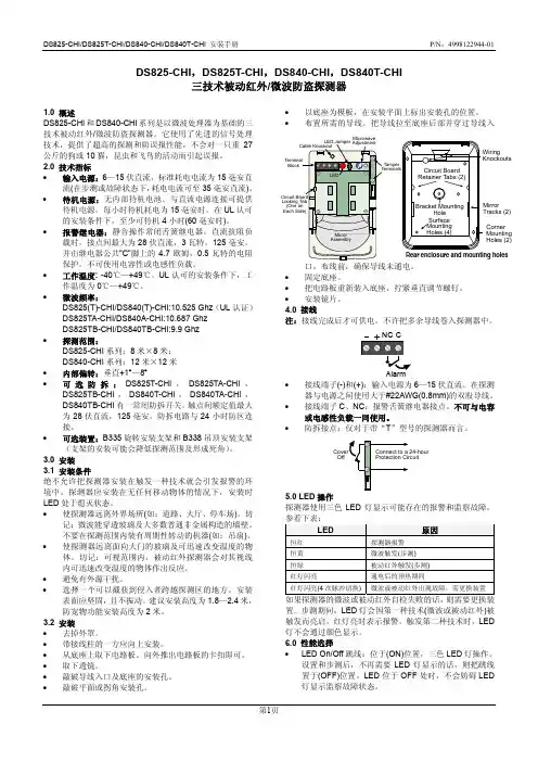
DS825-CHI/DS825T-CHI/DS840-CHI/DS840T-CHI 安装手册 P/N :4998122944-01第1页DS825-CHI ,DS825T-CHI ,DS840-CHI ,DS840T-CHI三技术被动红外/微波防盗探测器1.0 概述DS825-CHI 和DS840-CHI 系列是以微波处理器为基础的三技术被动红外/微波防盗探测器。
它使用了先进的信号处理技术,提供了超高的探测和防误报性能,不会对一只重27公斤的狗或10猫,昆虫和飞鸟的活动而引起误报。
2.0 技术指标 • 输入电源:6—15伏直流,标准耗电电流为15毫安直流(在步测或故障状态下,耗电电流可至35毫安直流)。
• 待机电源:无内部待机电池。
与直流电源连接可提供待机电源。
每小时待机耗电为15毫安时。
在UL 认可的安装条件下,至少可待机4小时(60毫安时)。
• 报警继电器:静音操作常闭舌簧继电器。
直流抗阻负载时,接点间最大为28伏直流,3瓦特,125毫安。
并由继电器公共"C"脚上的4.7欧姆,0.5瓦特的电阻保护。
不可使用电容性或电感性负载。
• 工作温度: -40℃—+49℃。
UL 认可的安装条件下,工作温度为0℃—+49℃。
• 微波频率:DS825(T)-CHI/DS840(T)-CHI:10.525 Ghz (UL 认证) DS825TA-CHI/DS840A-CHI:10.687 Ghz DS825TB-CHI/DS840TB-CHI:9.9 Ghz • 探测范围:DS825-CHI 系列:8米×8米; DS840-CHI 系列:12米×12米 • 内部偏转:垂直+1°—8° • 可选防拆:DS825T-CHI ,DS825TA-CHI ,DS825TB-CHI ,DS840T-CHI ,DS840TA-CHI ,DS840TB-CHI 有一常闭防拆开关。
HF 系统: 5.8GHz CW 电波,ISM 波段探测角度: 360°(吸顶安装)探测距离: 1-8m (半径.) (可调),(吸顶安装)延时设置: 8sec-12min, (可调)光控照度: 10-1000LUX, (可调)LED 专用可调光微波智能感应器说明书LX-MV-360S10MD-C电源电压: DC 25~80V 输出电流: <3A 微波功率: <0.3mW工作温度: -15°C~+70°C 保护等级: IP20, 2类安装位置: 室内, 吸顶技术参数产品简介产品特点这是一款0.3mW极微功率高频5.8GHz、360度探测的高精度数字型微波感应器,产品利用微波的多普勒效应发射与接收信号,采用嵌入式MCU软件作为信息处理方式,具有高探测精度,低误报率。
产品外形精美,结构紧凑合理,安装简便,维护率低,可置于灯体内部使用,也可以外接负载单独使用,产品可广泛应用于楼梯过道、洗手间、电梯口、办公室、仓库、工厂、宾馆、学校及更衣室等场所作安防、节能之用。
产品拥有多项技术专利,是您智能化生活的绝佳选择。
1、无辐射伤害:产品发射功率小于0.3mW,对人体无任何辐射伤害;2、LED专用可调光智能感应,具有晚间等待自动微亮开启功能,以及环境光超出100LUX时自动退出功能。
3、微亮等待功率从0%至30%可调。
L ED D C 0+-+-+- +-感应信息LED DC 25~80V+-+-+- +-SENSLUXTIMEDIM 接线方式LED 指示灯功能LED “+” “-”连接LED 灯板;DC“+” “-”连接DC 输入电压(输入范围DC 25~80V ) .产品应用微波可穿透玻璃、塑料、陶瓷及木制制品,因此可以安装在一定厚度的玻璃、塑料、陶瓷及木制等非金属表层里。
例如应用在LED灯具制品里,只要按照以下正确的接线示意图连接,您就可以轻松地将LED灯具改造为自动LED感应灯具。
10 DOF IMU Sensor (C)User Manual 1.FeatureTable 1: Product features2.Applications●Quadcopter;●Action game controller;●Indoor inertial navigation;●Self-balancing Robot;●Altimeter;●Industrial measuring instrument.3.Interface DescriptionsTable 2: Interface descriptions4.How to useWe will illustrate the usage of the module with an example of working with a STM32 series’development board.①Download the relative codes to the development board.②Connect the development board to a PC via a serial wire, and insert the module intothe I2C 2 interface on the development board. Please take attention to theconnection between the module and I2C 2 interface, each pin of the module shouldbe connected to its corresponding port on the I2C 2 interface and FSYN pin shouldbe kept suspended respectively.Figure 1: Connection between 10 DOF IMU Sensor module and STM32③Here is the configuration of the serial port, as Table 3 shows.Baud rate 115200Data bit 8Stop bit 1Parity bit noneTable 3: Serial port configuration④After powering 10 DOF IMU Sensor on, firstly, acceleration is calibrated at horizontalstate, and magnetic is calibrated later. After done, the qualify data will output from10 DOF IMU Sensor. For detail operations as below:A.Flatting 10 DOF IMU Sensor on the horizontal position and no motion isallowed,when serial terminal received the stable data from USART1, then pressJOYSTICK button down, LED1 is flashing and both of LED2 and LED3 turn off at the mean time.B.Rotating 10 DOF IMU Sensor 180 degrees around the Z axis on the horizontalposition, when serial terminal received the stable data from USART1, then press JOYSTICK button down, LED2 is flashing and both of LED1 and LED3 turn off at the mean time.C.Inverting 10 DOF IMU Sensor on the horizontal position, means holding thebackside of 10 DOF IMU Sensor upward and the positive side downward. Then press JOYSTICK button down, LED3 turn on forever indicating that magnetic calibration is complete, and both of LED1 and LED2 turn off at the mean time.D.Rotating 10 DOF IMU Sensor 180 degrees around the Z axis on the horizontalposition,recording and comparing with the magnetic data from serial terminal before and after rotating, if equaling to each other and behaving at opposite ofdirection, as a result, magnetic calibrating is successful.⑤If succeed to calibrate, serial terminal will received the qualify data as following:⑥The serial output is as followed:Roll, Pitch, Yaw Roll angle(°), Pitch angle(°), Yaw angle(°)Acceleration Acceleration value (LSB, translatable into theunit: g)Gyroscope Acceleration value (LSB, translatable into theunit: g)Magnetic Digital compass title angle (°)Pressure Pressure value (hPa)Altitude Altitude value (m)Temperature Temperature value (℃)Table 4: The meanings of the serial output5.Parameter calibration and calculation5.1 Altitude calibrationFor your first time to use 10 DOF IMU Sensor, you may find that there is a large difference between the altitude value outputted by the module and the actual altitude. This is because10 DOF IMU Sensor calculates the pressure at sea level P0 with the Altitude of its currentposition and the measured pressure, providing that both module current position andpressure are known. And this P0 will be taken as a benchmark for subsequent calculations.For more detailed information, please refer to BST-BMP180-DS000-09.pdf:Altitude:With the benchmark P0, you can calculate the Altitude of the module current position as well.Therefore, you should firstly set the altitude of the module current position as a benchmark in the sample code 10 DOF IMU Sensor\SRC\HardWare\BMP180\ BMP180.h (normally, it should be the absolute altitude of your position now, unit:5.2Acceleration calculationAcceleration measured by the program is in the unit of LSB (Least Significant Bit), however it is usually translated into the unit of gravitational acceleration (g) in practical application. In the sample code of the module, the default setting is AFS_SEL=0, of which the corresponding measurement range is 16384 LSB/g (±2g), so the actual measured acceleration would be: a=Acceleration/16384 ,Unit:gFor more detailed information, please refer toPS-MPU-9255.pdf Page 9RM-MPU-9255.pdf Page145.3Gyroscope angular velocity calculationGyroscope angular velocity calculationAngular velocity measured by the program is in the unit of LSB (Least Significant Bit), however it is usually translated into the unit of angular velocity (°/sec) in practical application. In the sample code of the module, the default setting is FS_SEL=2, of which the corresponding measurement range is 32.8 LSB/(°/s) (±1000°/sec), so the actual measured angular velocity would be:ω=Gyroscope/32.8 ,Unit:°/sFor more detailed information, please refer toPS-MPU-9255.pdf Page 8RM-MPU-9255.pdf Page14。
微波传感器的原理及应用【摘要】微波传感器是利用微波的传输性能好、易反射、被吸收功率易测量等特点,用专门的微波振荡器来产生微波,特定的天线收发微波,在实际生产生活中用来测量被测物的距离、厚度、传输媒介性质等许多应用。
【关键词】微波传感器反射式遮断式一、微波的基础知识1、微波的性质与特点微波是波长为1,1000mm的电磁波,它既具有电磁波的性质,又不同于普通无线电波和光波。
微波相对于波长较长的电磁波具有下列特点:1(定向辐射装置容易制造;2(遇到工作障碍物易于反射;3(绕射能力较差;4(传输性能良好,传输过程中受烟、火馅、灰尘、强光等的影响很小;5(介质对微波的吸收与介质的介电常数成比例,水对微波的吸收能力最强。
正是这些特点构成了微波检测的基础。
2、微波振荡器与微波天线微波振荡器是产生微波的装置。
由于微波很短,频率很高(300MHz,300GHz),振荡回路具有非常微小酌电感与电容,故不能用普通的电子管与晶体管构成微波振荡器。
构成微波振荡器的器件有调速管、磁控管或某些固体元件。
小型微波振荡器也可采用体效应管。
由微波振荡器产生的振荡信号需要用波导管(波长在1000cm以上可用同轴线)传输,并通过天线发射出去。
为了使发射的微波具有尖锐的方向性,天线具有特殊的结构。
常用的天线如图1所示,有喇叭形天线、抛物面天线、介质天线与隙缝天线等。
喇叭形天线结构简单,制造方便,可看作波导管的延续。
喇叭形天线在波导管与敞开的空间之间起匹配作用以获得最大的能量输出。
抛物面天线犹如凹面镜产生平行光,这样位微波发射的方向性得到改善。
图1 常用微波天线(a) 扇形喇叭天线 (b) 圆锥形喇叭天线(c) 旋转抛物面天线 (d) 抛物柱面天线二、微波传感器由发射天线发出的微波,遇到被测物时将被吸收或反射,使功率发生变化。
若利用接收天线,接收通过被测物或由被测物反射回来的微波,并将它转换成电信号,再由测量电路测量和指示,就实现了微波检测过程。
符合标准:GB/T 14048.5 安装、使用产品前,请仔细阅读使用说明书并妥善保管、备用安全告知在安装、操作、运行、维护、检查之前,请务必认真阅读本说明书,并按照说明书上的内容准确安装、使用本产品。
危险:●严禁湿手操作报警触头;●使用中,严禁触摸导电部位;●维护与保养时,必须确保产品不带电;●严禁用短路的办法来测试产品。
注意:●安装、维护与保养时,应由具有专业资格的人员操作;●产品的各项特性出厂时已整定,使用中不能自行拆装或随意调节;●使用前请确认产品额定电压、额定电流、频率及特性是否符合工作要求;●为防止相间短路,应对接线端裸露导线或铜母线进行绝缘处理;●如果产品在开箱时有破损或异常响声,应立即停止使用并联系供应商;●本产品不适用于频繁启动的电动机、电热设备、电容柜、高感性或高容性负载和高温环境等特殊场合;●产品报废时,请做好产品废弃物处理,谢谢您的合作。
目录1主要用途及适用范围 (1)2 产品型号及含义、面板介绍 (1)3 正常使用、安装及运输条件 (2)3.1正常使用、安装条件 (2)3.2正常贮存和运输条件 (2)4技术特性 (2)4.1主要技术性能参数 (2)4.2其它技术参数 (2)5 外形及安装尺寸 (3)5.1外形及安装尺寸 (3)5.2接线示意图 (3)6 安装和使用(维护) (4)7 开箱检查 (5)8公司承诺 (5)1主要用途及适用范围SD3系列辅助触头主要用于交流50/60Hz、额定电压不超过415V、额定电流1A~6A的报警电路中。
此系列报警触头通过远程接报警器等方式实现远程断路器的故障脱扣报警功能。
2 产品型号及含义、面板介绍●产品型号及含义设计序号小型报警触头系列●面板介绍说明:1公司商标 2产品名称 3指示标志 4进线端子 5常开出线端子 6常闭出线端子7技术参数 8拼装示意图 9符合标准 10认证标识 11扭矩、剥线指示及接线端子指示12 敲落孔盖3 正常使用、安装及运输条件3.1正常使用、安装条件a)周围空气温度上限不超过+70℃, 下限不超过-35℃,并且在24小时内平均温度不超过+35℃;b)安装地点的海拔不超过2000m;c)温度为+40℃时,空气的相对湿度不超过50%;在较低温度下允许有较大的相对湿度,例如在+20℃时,相对湿度不超过90%,对由于温度变化偶尔产生的凝露应采取特殊的保护措施;d)报警触头安装场所附近的外磁场,在任何方向均不应超过地磁场的5倍;e)安装在无爆炸危险的介质中,且介质中无足以腐蚀金属和破坏绝缘的气体与尘埃;f)安装在无显著冲击振动及无雨雪侵袭的地方;g)污染等级:2级;h)安装类别:Ⅱ类、Ⅲ类;i)应安装于配电箱、配电柜或盒中。
新型红外雷达感应模块(电源)产品概述:新型红外雷达感应模块(电源)是利用PIR 热释电与多普勒效应相结合原理设计而成的人体移动信号侦测器,它以非接触方式扫描人体PIR热释电信号的位置是否发生移动,继而产生相应的开关操作。
该产品具有抗射频干扰能力强、不怕风吹草动、树叶摇曳、电风扇转动、空调冷热气体流动、浴室浴霸温度骤变......不受温度、湿度、强光、噪音、气流、尘埃等外界因数影响,能透过一定厚度的塑胶、玻璃、木制品等金属以外的物体,而对其侦测能力没有影响,能够非常方便的应用到设备控制、环境辅助光源控制、地下停车场、仓库、通道、走廊、洗手间等室外的照明及防盗报警、视频监控、自动化设备控制等各种领域。
功能特点:新型红外雷达感应模块(电源)采用发射、接收为一体的平面天线和PIR热释电红外解码系统BISS0001形成的红外雷达移动波侦测新技术,通过多普勒扫描,侦测人体、车辆的动态信号,对灯具、报警装置等进行有效控制。
产品独创抗干扰新技术,相互不干扰,安装不必考虑间接距离问题!可以安装在天花板或灯具部,而侦测能力不会受到影响,更简洁、更美观、更隐蔽、更神秘、更安全!模块类型1、交流型:A C95-250V宽电压,适应各种不同地区电网电压。
可控硅控制A C输出,无触点、无噪音、无污染、寿命长。
具有自动测光管理功能(出厂未安装光敏电阻),实现白天(光线充足)呈关闭状态,晚上(光线不足)人来灯亮、人走灯灭。
可做吸顶灯、日光灯及各种灯具、电器等的自动控制。
交流模块技术参数❖工作电压:A C110V-250V(50-60H z)❖负载功率:阻性负载150W(节能灯、L E D灯80W)❖输出方式:可控硅控制、A C交流输出❖自身功耗:静态功耗≤1m W❖感应围:10-15米❖感应角度:墙壁安装180°、吸顶安装360°❖触发方式:雷达扫描、人体感应、重复触发❖延时时间:30秒钟(可定做各种延时时间)❖模块尺寸:36m m*23m m*23m m❖环境温度:-30℃-70℃2、直流型:D C6-24V输入,有人在感应区活动时,输出高电平,无人活动时转换为低电平。
C波段微波传感器技术说明书
一、产品概述
本微波传感器通过多普勒原理用于检测移动人体信号。
工作于C波段的国际通用频率,具有比X和K波段更低的无线链路传播损耗。
该模块探测天线具有方向性,在天线正前方120°范围内灵敏度很高,具有比全向天线更远的作用距离和抗干扰能力。
该模块内部集成微波振荡器、检波器和高增益中频放大器,具有更高的集成度。
模块直接输出低阻抗多普勒信号,用户只需将中频输出接入控制器输入端即可使用,无需用户二次开发中频放大电路。
操作简单,性价比高。
二、产品照片
实物图片
天线方向图
三、技术参数
感应检测频率 5.8GHZ±75MHz
发射功率密度<<5mW/c m2
辐射角水平角120°,垂直角110°
检测距离不小于12米
5cm/秒(沿天线纵横线测试)
最小检测运动
速度
中频输出无信号时DC 2.5V
工作电压 3.3~5.5V
工作电流<25mA
温度范围
-40°C
至+85°C 外形尺寸:35mmX34mmX4.8mm
(不包括天线高度)
四、接线说明
五、外形尺寸
2012.2。