
PXR3说明书
- 格式:pdf
- 大小:1.22 MB
- 文档页数:74


宝峰3R功能操作说明一. 功能描述:1、直观的液晶LCD菜单式操作;2、电池:3.7V 1200mAh可充电锂电池;3、频率范围UHF:400MHz~470MHz、136MHz~174MHz;4、宽/窄带选择:25KHz/12.5KHz;5、射频输出功率:H:2W、L:1.0W;6、模拟亚音频CTCSS(50个)和数字亚音频CDCSS(104组);7、信道存储编制:有99个存储信道(1个呼叫应急信道);8、发射限时。
(OFF、30、60、90、120、150、180S);9、声控功能:OFF/1----9档10、音频呼叫(1750KHz)功能;11、静嗓级别设置。
(0-9级);12、电子音量调节(8档)13、背光灯开/关/Key;14、省电功能;15、监听功能;16、开机自动检测显示电压;17、低电压指示/报警;18、键盘提示音。
19、键盘锁20、FM收音机功能(频率范围为87.0~108.0MHz)21、恢复出厂设置功能22、电脑编程功能二、图标显示与描述三、按键说明(一)按键定义[DIAL]:主调谐旋钮,用于设定操作频率、菜单功能选择及其它调整;[PTT]:发射键,发射时按下这个开关,发射结束后松开;[MON/VOL]:按住是监听功能,按一下是Volume和Dial切换键。
[POWER]:开/关机,按住这个键2秒钟开机或关机[F/Alert]:短按为激活第二功能(F键);长按为报警(紧急呼叫功能);[MODE]:功能键:短按下此键进入功能设置菜单长按为键盘上锁LCD显示图标。
重复此步骤为解锁。
(注:键盘上锁后功能键、确认键、收音机键、步进开关操作无效。
)[V/M]:短按为全频模式下UHF和VHF切换功能。
长按为全频模式和信道模式切换功能。
[LAMP/FM]:短按手电开关长按为收音机功能F+[MODE]:扫描功能。
F+[V/M]:全频模式下存储功能。
F+[DIAL]:+-1Mhz[MON/VOL]+ [DIAL]:调节音量大小。

T i me rf unct i on H e a t i n g /c o o li n g c on t ro l f u n c t i o n R am p/s o a kf u n c t i o nU L/C -U L /C E m a r k P ID +fu z z y f u n ct i o n Di g i t a l i npu t Co m m u n i c a t i o nf u n c t i o n R e -T r a n s m i s s i o no u t p u t L ar g e L ED d i sp l a y F r o n t w a t e r p r o o fst r u c t u r e (N E M A -4X /I P 66)S el f -t un i ng ECNO:1138cModel:PXR3(1/32 DIN, 24×48mm)Digital Temperature ControllerMicro Controller XSeries2Large LED display and front waterproof structurePID + self-tuning, PID + fuzzy controlFor calculating the optimum PID parameters, the auto tuning and self-tuning functions are installed. Also, fuzzy control function is a standard feature for suppressing the overshoot and improving the response to disturbance. Thanks to these functions,optimum control parameters suitable for each application is munication function (option)With RS-485 (Modbus »protocol) interface, a connection with computer, touch panel or PLC is allowed.Digital input (option)External digital input allows one of the following functions.● Change the set value (front SV0, SV1 to 3)● Start/stop the control action ● Start/reset the ramp/soak ● Start/stop the auto tuning ● Cancel the alarm latch● Start the incorporated timerNote:The alarm latch means to hold thestatus once alarm is output.The front display and operation section is dust-proof and waterproof conforming to NEMA-4X:IP66. The front panel is washable with water.(*NOTE)(*Note) Provided that the panel is installed with our genuine watertightpacking.Easy-to-see, large LED display (1.3 times larger than current models)● Self-tuningAt power on, changing a set value or during external disturbance, tuning is madeautomatically so that the PID parameters arecould not be optimized.1/32 DIN (24 ×48 mm) temperature controller PXR3● Fuzzy controlSuppresses the overshoot without wasting start up time.Also, quickly reverts to set points at the event of Touch panelFuji Programmable Operation Display (UG series)3Timer function (option)By Digital input, ON-delay or OFF delay timer can be started.That is, relay output is turned on/off after certain period of time preset in parameter dLY1/dLY2. As for relay output, alarm output relays are used. Up to 2 timer outputs can be obtained.Ramp/soak function (option)Changes the set value (SV) as the time elapses according to a predetermined program pattern. The instrument can program up to 8 ramp/soak steps.Heating/cooling control (option)By a single controller both heating and cooling control output are obtained. (Both control outputs 1 and 2 are used.)PXR, Suitable for various temperature controlsPXR3Heat control outputRecorder PHRPXR3PXR3Temp inputcool control outputPV TransmissionSpecifications and performance <General specifications>4PXR3Note 1: For current input connect the supplied 2501 resister at theinput terminal.Note 2: When the measuring range exceeds 1000°C (1832°F), decimalpoint cannot be used.Note: Basic insulation (dielectric strength 1500 V AC) between blocksdelimited by line .Functional insulation (dielectric strength 500 V AC) betweenblocks delimited by line .Non isolated between blocks which are not delimited from eachother.<Caution in use>The following table shows the differences among PX-series models.When replacing the device, be sure to use the one with identical outputspecifications.56Note 1No combination with alarm (2 points) (The code F, G of 9th digit should not be ordered.)Note 2No combination with control output 2 (A, C, E of 7th digit should not be ordered.)Note 3Control output 2, communication, external input 2, 24V power supply.The code A, C, E of 7th digit, A, B, C of 10th digit, M, N, T, V, W of 11th digit should not be ordered.When delivering, the input signal, measuring range and set value are as follows:Thermocoupule input : type K, 0 to 400°C, set value at 0°C Resistance bulb input : 0 to 150°C, set value at 0°C Voltage or current input : 0 to 100%, set value at 0%The input signal of thermocouple and each measuring range should be specified except for the above specifications.When delivering, the control output action is set at reverse for control output 1, set at direct for control output e the front key to change the control action between reverse and direct.7Re-Transmission RecorderPrinted in Japan 2002-9/00FISInformation in this catalog is subject to change without notice.Over-temperature ProtectionAny control system design should take into account that any part of the system has the potential to fail.For temperature control systems, continued heating should be considered the most dangerous condition, and the machine should be designed to automatically stop heating if unregulated due to the failure of the control unit or for any other reason.The following are the most likely causes of unwanted continued heating:1) Controller failure with heating output constantly on2) Disengagement of the temperature sensor from the system 3) A short circuit in the thermocouple wiring4) A valve or switch contact point outside the system is locked to keep the heat switched on.In any application where physical injury or destruction of equipment might occur, we recommend the installation of independent safety equipment, with a separate temperature sensor, to disable the heating circuit in case of overheating.The controller alarm signal is not designed to function as a protective measure in case of controller failure.SPECIAL ATTENTION NEEDED for all Micro Controller X series products(Please read carefully the following instructions.)。
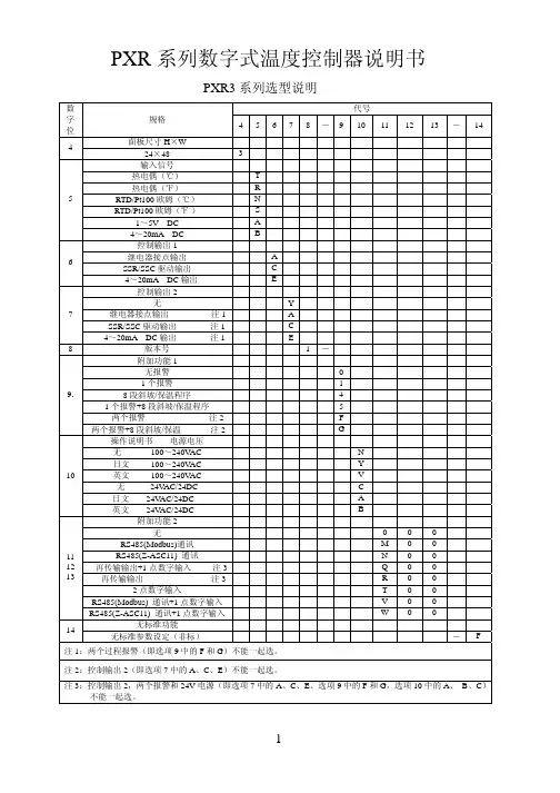
PXR 系列数字式温度控制器说明书PXR3系列选型说明 代号 数字位规格 45678-9101112 13 - 14面板尺寸H ×W 4 24×48 3 输入信号 热电偶(℃) T 热电偶(℉) R RTD/Pt100欧姆(℃) N RTD/Pt100欧姆(℉。
) S 1~5V DC A 54~20mA DC B 控制输出1 继电器接点输出 A SSR/SSC 驱动输出 C 64~20mA DC 输出 E 控制输出2 无 Y 继电器接点输出 注1 A SSR/SSC 驱动输出 注1 C 74~20mA DC 输出 注1 E 8版本号 1- 附加功能1 无报警 0 1个报警 1 8段斜坡/保温程序 4 1个报警+8段斜坡/保温程序 5 两个报警 注2 F 9.两个报警+8段斜坡/保温 注2 G 操作说明书 电源电压 无 100~240V AC N 日文 100~240V AC Y 英文 100~240V AC V 无 24V AC/24DC C 日文 24V AC/24DC A 10英文 24V AC/24DC B 附加功能2 无 0 0 0 RS485(Modbus)通讯 M 0 0 RS485(Z-ASC11) 通讯 N 0 0 再传输输出+1点数字输入 注3 Q 0 0 再传输输出 注3 R 0 0 2点数字输入 T 0 0 RS485(Modbus) 通讯+1点数字输入 V 0 0 111213RS485(Z-ASC11) 通讯+1点数字输入 W 0 0 无标准功能14 无标准参数设定(非标) - F 注1:两个过程报警(即选项9中的F 和G )不能一起选。
注2:控制输出2(即选项7中的A 、C 、E )不能一起选。
注3:控制输出2,两个报警和24V 电源(即选项7中的A 、C 、E 、选项9中的F 和G ,选项10中的A 、 B 、C )不能一起选。
PXR4系列选型说明 代号 数字位规格 45678-910 11 12 13面板尺寸W ×H 4 48×48mm 4 输入信号 热电偶(℃) T 热电偶(℉) R RTD/Pt100欧姆(℃) N RTD/Pt100欧姆(℉。
富士PXR系列温度控制器参数设定
一、设置参数:
1.按SEL约1秒进入第一组参数表;
2.按SEL约3秒进入第二组参数表;
3.按SEL约5秒进入第三组参数表;
4.以上如持续按SEL不放,将回到原始状态;
5.进入参数模式时,如超过30秒无设定动作,显示将回到原始状态。
二、无法设定参数时,检查LOC是否锁定
锁定按键(LOC范围:0,1,2,3,4,5)
*按键锁LOC
*本功能可将控制器内部参数依不同使用程度设定。
0:所有参数均可盘面/通讯设定;
1:所有参数盘面均不可设定,只能通讯设定;
2:仅能盘面键入设定值,所有参数均可通讯设定;
3:所有参数均可盘面设定,无法通讯设定;
4:所有参数均可盘面通讯设定;
5:仅能设定设定值,所有参数均无法设定。