速度传感器SA(SC)使用说明书
- 格式:doc
- 大小:169.50 KB
- 文档页数:6
![ZDC30-1[1].2跑车防护装置安装规范](https://uimg.taocdn.com/19c12bbbfd0a79563c1e7206.webp)
3.1 传感器安装3.1.1传感器(SA、SC)的位置确定:3.1.1.1 A段距离的确定取上变坡点下大于一列车长度装置“SA”传感器,考虑到挡车栏打开提前量,传感器安装距挡车栏8V处(8-为提升时间,V-为矿车速度);若有偏口或岔道一定要错开偏口岔道不小于15米装置,推荐取上变坡点下30米处装置SA传感器。
3.1.1.2“SA”传感器到吸能器的距离S(B段)因为:ZDC30-1.2型跑车防护装置的收方绞车将挡车栏从下限位提升到2.4米的高度的时间最大为8s.可以根据实际情况,确定挡车栏的提升高度,提升时间为挡车栏提升高度/0.3.所以:S=T×Vmax,其中Vmax为绞车正常运行时的最大速度,同理“SC”传感器到挡车栏的距离(C段)的计算同“SA”。
注:“SA”、“SC”传感器确定装置位置时一定要错开偏口或岔道大于15米。
若采取轨道单传器程序,即去掉“SC”传感器的位置。
3.1.2轨道的截取及钻孔(如1图示)在确定好安装“SA”、“SC”位置处(尽量选择不放在水沟的一侧),量好距离及道夹板的孔距等,在地面上截取同型号的钢轨3米2根,若钢轨为22kg/m 以上型号的准备为Φ18、Φ24的钻头,若为22kg/m以下型号的准备Φ18、Φ22的钻头。
在3米钢轨上从上到下2米处确定要打孔的地方,在此处护好道夹板,然后从轨面正中心用Φ18的钻头向下钻通,然后用Φ24或Φ22的钻头扩大,具体尺寸如图。
钻完孔后将传感器(SA或SC)放入看是否合适,不能高出轨道面,也不能低于轨道面,一定要平齐。
4.电气连接图A1B1C1A2B2C2LN左侧箱接线图AC660V/380V (电源进线)接电机S+S-Y0Y1Y2Y3(Y-)传感器SA传感器SC1传感器SE 传感器、报警箱(联网不接)公共电源负三相660V或380V单机接报警箱(联网时Y1接RS+,Y2接RS-,Y0,Y3不接)SA SC(SC1)SESF速度传感器传感器S+S-SA S+S-SCS+S-SE S+S-SF(兰)(黑)(棕)(兰)(黑)(兰)(黑)(兰)(黑)SE SC1右侧箱接线图传感器公共电源正(棕)(棕)(棕)SFSB传感器SF 传感器SC传感器SA1人车SB (SA1)单台监控箱接线图联网接线顺序为Y-、Y0、Y1、Y2、Y3重复6路,S+、S-、X16、SBY0Y1Y2Y3Y-接报警灯(七彩灯)开启(绿灯)接公共负极端子(黄灯)运行(红灯)闭合X16SB接人车/货车开关S+接公共正极接复位复位(单传感器)轨道传感器安装方式中,轨道传感器分别接“SA ”、“SC ”4.1单机工作时连接关系如下图所示共端开关运行(黄灯)控制电机用交流接线原理图660VK M 2C Z 2C Z 14.2联网通讯工作连接关系如下图所示I O S S S R S R S R E P L R S R S E H P L C R SA 6装置各部分安装好后,按照设计要求,正确连接装置各部件,连接完成后,认真核对,确保连接无误情况下,加电调试。
技术指标产品技术指标如有变化,恕不另行通知。
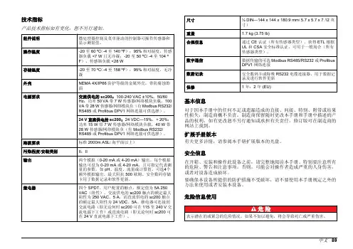
尺寸½ DIN—144 x 144 x 180.9 mm (5.7 x 5.7 x 7.12 英寸)重量1.7 kg (3.75 lb)合规信息通过 CE 认证(所有传感器类型)。
获得 ETL 根据UL 和 CSA 安全标准认证,可用于一般场合(所有传感器类型)。
数字通信数据传输的可选 Modbus RS485/RS232 或 Profibus DPV1 网络连接数据记录安全数码卡或特殊 RS232 电缆连接器,用于数据记录及进行软件更新保修1 年;2 年 (EU)基本信息对于因本手册中的任何不足或遗漏造成的直接、间接、特别、附带或结果性损失,制造商概不负责。
制造商保留随时更改本手册和手册中描述的产品的权利,如有更改恕不另行通知或承担有关责任。
修订版可在制造商的网站上找到。
扩展手册版本有关更多详情,请参阅本手册扩展版本的光盘。
安全信息在开箱、安装和操作此设备之前,请完整地阅读本手册。
特别要注意所有的危险、警告和注意事项。
否则,可能会对操作者造成严重的人身伤害,或者对设备造成损坏。
要确保本设备所提供的防护措施不受破坏,请不要使用本手册规定之外的方法来使用或者安装本设备。
危险信息使用警告标签请阅读贴在仪器上的所有标签和标记。
如未遵照这些安全标签的指示操作,则可能造成人身伤害或仪器损坏。
Hach 合规认证加拿大有干扰设备管理规范,IECS-003,A 类:制造商支持测试记录留存。
此 A 类数字设备符合加拿大有干扰设备管理规范的所有要求。
Cet appareil numèrique de la classe A respecte toutes les exigences du Rëglement sur le matÈriel brouilleur du Canada.FCC 第 15 部分,“A”类限制制造商支持测试记录留存。

High TemperatureIndustrial VRS Magnetic Speed SensorsDESCRIPTIONHigh Temperature VRS sensors are designed for use inapplications where the sensor is exposed to temperatures up to 260 ºC [450 ºF]. Sealed Front-End versions are available for applications where the sensor is exposed to fluids, lubricants or adverse environmental conditions.Passive VRS (Variable Reluctance Speed) Magnetic Speed sensors are simple, rugged devices that do not require an external voltage source for operation.A permanent magnet in the sensor establishes a fixedmagnetic field. The approach and passing of a ferrous metal target near the sensor’s pole piece (sensing area) changes the flux of the magnetic field, dynamically changing its strength. This change in magnetic field strength induces a current into a coil winding which is attached to the output terminals.The output signal of a VRS sensor is an ac voltage that varies in amplitude and wave frequency as the speed of themonitored device changes, and is usually expressed in peak to peak voltage (Vp-p).One complete waveform (cycle) occurs as each target passes the sensor’s pole piece. If a standard gear were used as a target, this output signal would resemble a sine wave if viewed on an oscilloscope.Honeywell also offers VRS sensors for general purpose, high output, power output, high resolution and hazardous location applications, as well as low-cost molded OEM versions.FEATURES• Self-powered operation• Direct conversion of actuator speed to output frequency • Simple installation • No moving parts• Designed for use over a wide range of speeds • Adaptable to a wide variety of configurations• Customized VRS products for unique speed sensingapplications• Housing diameters: 5/8 in (M16), 3/8 in (M12),1/4 in (8M)• Housing material/style: stainless steel threaded • Terminations: MS3106 connector, preleaded • Output voltages: 4.7 Vp-p to 125 Vp-pPOTENTIAL APPLICATIONS• Engine RPM (revolutions per minute) measurement onaircraft, automobiles, boats, buses, trucks and rail vehicles• Motor RPM measurement on drills, grinders, lathes andautomatic screw machines• Motor RPM measurement on precision camera, taperecording and motion picture equipment• Process speed measurement on food, textile, paper,woodworking, printing, tobacco and pharmaceutical industry machinery• Motor speed measurement of electrical generatingequipment• Speed measurement of pumps, blowers, mixers, exhaustand ventilating fans• Flow measurement on turbine meters• Wheel-slip measurement on autos and locomotives • Gear speed measurementHigh Temperature2 /sensing5/8 INCH (M16*) SENSORS (All dimensions for reference only. mm/[in]) *Contact Honeywell for availability of metric mounting thread versions.LOW RESISTANCE COILS FOR HIGH FREQUENCY APPLICATIONS General SpecificationsTest Condition SpecificationsParameter Characteristic Parameter Characteristic Parameter Characteristic Min. output voltage 25 Vp-p Inductance 30 mH max. Surface speed 25 m/s[1000 in/s]Coil resistance 65 Ohm typ. Gear pitch range 24 DP (module 1.06) or coarser Gear 20 DP(module 1.27)Pole piece diameter 2,69 mm [0.106 in] Optimum actuator 20 DP (module 1.27) Air gap 0,127 mm[0.005 in]Min. surface speed0,50 m/s [20 in/s] typ. Max. operating frequency50 kHz typ. Operating temp. range-55 ºC to 230 ºC [-67 ºF to 450 ºF] Vibration N/A Mounting thread 5/8-18 UNF-2ATerminationMS3106 connectorLoadresistance100 kOhmHIGH RESISTANCE COILS FOR MAXIMUM OUTPUT VOLTAGE APPLICATIONS General SpecificationsTest Condition SpecificationsParameter Characteristic Parameter Characteristic Parameter Characteristic Min. output voltage 125 Vp-p Inductance 450 mH max. Surface speed 25 m/s[1000 in/s]Coil resistance 1055 Ohm typ. Gear pitch range 24 DP (module 1.06) or coarser Gear 20 DP(module 1.27)Pole piece diameter 2,69 mm [0.106 in] Optimum actuator 20 DP (module 1.27) Air gap 0,127 mm [0.005 in] Min. surface speed 0,25 m/s [10 in/s] typ. Max. operating frequency 15 kHz typ. Operating temp. range-55 ºC to 230 ºC [-67 ºF to 450 ºF] Vibration N/A Mounting thread 5/8-18 UNF-2ATerminationMS3106 connectorLoad resistance100 kOhmIndustrial VRS Magnetic Speed SensorsHoneywell Sensing and Control 35/8 INCH (M16*) SENSORS CONTINUED (All dimensions for reference only. mm/[in]) *Contact Honeywell for availability of metric mounting thread versions.NOMINAL RESISTANCE COILS FOR LOW IMPEDANCE LOAD APPLICATIONS General SpecificationsTest Condition SpecificationsParameter Characteristic Parameter Characteristic Parameter Characteristic Min. output voltage 45 Vp-p Inductance 85 mH max. Surface speed 25 m/s[1000 in/s]Coil resistance 141 Ohm typ. Gear pitch range 12 DP (module 2.11) or coarser Gear 8 DP(module 3.17)Pole piece diameter 4,75 mm [0.187 in] Optimum actuator 8 DP (module 3.17) Air gap 0,127 mm [0.005 in]Min. surface speed 0,38 m/s [15 in/s] typ. Max. operating frequency 40 kHz typ. Operating temp.range-55 ºC to 230 ºC [-67 ºF to 450 ºF] Vibration N/A Mounting Thread 5/8-18 UNF-2ATerminationMS3106 ConnectorLoadresistance1.25 kOhmHigh Temperature4 /sensing5/8 INCH SEALED FRONT-END SENSORS (All dimensions for reference only. mm/[in]) (No metric available.)NOMINAL RESISTANCE COILS FOR LOW IMPEDANCE LOADS APPLICATIONS General SpecificationsTest Condition SpecificationsParameter Characteristic Parameter Characteristic Parameter Characteristic Min. output voltage60 Vp-p Inductance 85 mH max. Surface speed 25 m/s[1000 in/s]Coil resistance 120 Ohm to 162 Ohm Gear pitch range 12 DP (module 2.11) or coarser Gear 8 DP(module 3.17)Pole piece diameter 4,39 mm [0.173 in] Optimum actuator 8 DP (module 3.17) Air gap 0,127 mm[0.005 in]Min. surface speed0,38 m/s [15 in/s] typ. Max. operating frequency40 kHz typ. Operating temp. range-54 ºC to 220 ºC [-65 ºF to 428 ºF] Vibration N/AMounting Thread 5/8-18 UNF-2ATerminationMS3106 connectorLoadresistance 1.25 kOhmIndustrial VRS Magnetic Speed SensorsHoneywell Sensing and Control 53/8 INCH (M12*) SENSORS (All dimensions for reference only. mm/[in]) *Contact Honeywell for availability of metric mounting thread versions.General SpecificationsTest Condition SpecificationsParameter Characteristic Parameter Characteristic Parameter Characteristic Min. output voltage15 Vp-p Inductance 31 mH max. Surface speed 25 m/s[1000 in/s]Coil resistance 110 Ohm max. Gear pitch range 26 DP (module 0.98) or coarser Gear 20 DP(module 1.27)Pole piece diameter 2,36 mm [0.093 in] Optimum actuator 24 DP (module 1.06) ferrous metal gear Air gap 0,127 mm[0.005 in]Min. surface speed0,75 m/s [20 in/s] typ. Max. operating frequency50 kHz typ. Operating temp. range-40 ºC to 205 ºC [-40 ºF to 400 ºF] Vibration N/A Mounting thread 3/8-24 UNF-2ATermination24 AWG Teflon-insulated leadsLoadresistance 100 kOhmHigh Temperature6 /sensing1/4 INCH (M8*) MINIATURE SENSORS (All dimensions for reference only. mm/[in]) *Contact Honeywell for availability of metric mounting thread versions.General SpecificationsTest Condition Specifications Parameter Characteristic Parameter Characteristic Parameter CharacteristicMin. output voltage 4.7 Vp-p Inductance 13 mH max.Surface speed 25 m/s[1000 in/s]Coil resistance 137 Ohm max. Gear pitch range36 DP (module 0.70) or coarserGear 20 DP(module 1.27) Pole piece diameter 1 mm [0.040 in] Optimum actuator 28 DP (Module 0.90)ferrous metal gear Air gap 0,127 mm [0.005 in] Min. surface speed0,89 m/s [35 in/s] typ. Max. operating frequency70 kHz typ.Operating temp. range-40 ºC to 230 ºC [-40 ºF to 450 ºF] Vibration Mil-Std 202F Method 204DMounting thread 1/4-40 UNS-2ATermination30 AWG Teflon-Insulated LeadsLoadresistance100 kOhmIndustrial VRS Magnetic Speed SensorsHoneywell Sensing and Control 71/4 INCH SEALED FRONT-END SENSORS (All dimensions for reference only. mm/[in]) (No metric available.)General SpecificationsTest Condition SpecificationsParameter Characteristic Parameter Characteristic Parameter Characteristic Min. output voltage 5.2 Vp-p Inductance 85 mH max. Surface speed 25 m/s[1000 in/s]Coil resistance 20 Ohm to 45 Ohm Gear pitch range 36 DP (module 0.70) or coarser Gear 20 DP(module 1.27)Pole piece diameter 1 mm [0.040 in] Optimum actuator 28 DP (module 0.90) ferrous metal gear Air gap 0,127 mm [0.005 in]Min. surface speed 0,89 m/s [35 in/s] typ. Max. operating frequency 70 kHz typ. Operating temp.range-73 ºC to 230 ºC [-100 ºF to 450 ºF] Vibration Mil-Std 202F Method 204DMounting Thread 1/4-40 UNS-2ATermination 28 AWG Teflon-insulated leadsLoadresistance 100 kOhmAutomation and Control Solutions Sensing and Control Honeywell1985 Douglas Drive North Minneapolis, MN 55422 /sensing 005877-1-EN IL50 GLO Printed in USAMarch 2007Copyright © 2007 Honeywell International Inc. All rights reserved.WARNINGPERSONAL INJURYDO NOT USE these products as safety or emergency stop devices or in any other application where failure of the product could result in personal injury.Failure to comply with these instructions could result in death or serious injury.WARRANTY/REMEDYHoneywell warrants goods of its manufacture as being free of defective materials and faulty workmanship. Honeywell’s standard product warranty applies unless agreed to otherwise by Honeywell in writing; please refer to your orderacknowledgement or consult your local sales office for specific warranty details. If warranted goods are returned to Honeywell during the period of coverage, Honeywell will repair or replace, at its option, without charge those items it finds defective. The foregoing is buyer’s sole remedy and is in lieu of all other warranties, expressed or implied, including those of merchantability and fitness for a particular purpose. In noevent shall Honeywell be liable for consequential, special, or indirect damages.While we provide application assistance personally, through our literature and the Honeywell web site, it is up to the customer to determine the suitability of the product in the application.Specifications may change without notice. The information we supply is believed to be accurate and reliable as of this printing. However, we assume no responsibility for its use.WARNINGMISUSE OF DOCUMENTATION• The information presented in this product sheet is forreference only. Do not use this document as a product installation guide.• Complete installation, operation, and maintenanceinformation is provided in the instructions supplied with each product.Failure to comply with these instructions could result in death or serious injury.SALES AND SERVICEHoneywell serves its customers through a worldwide network of sales offices, representatives and distributors. For application assistance, current specifications, pricing or name of the nearest Authorized Distributor, contact your local sales office or:E-mail:*********************Internet: /sensing Phone and Fax:Asia Pacific +65 6355-2828 +65 6445-3033 Fax Europe +44 (0) 1698 481481+44 (0) 1698 481676 FaxLatin America +1-305-805-8188+1-305-883-8257 Fax USA/Canada +1-800-537-6945+1-815-235-6847 +1-815-235-6545 Fax。
目录第一章概述 (3)1.1. KTC102装置简介 (3)1.2. 装置组成及配置图 (3)1.3. 装置功能 (4)第二章装置组成详解 (6)2.1. KTC102.1/-A型控制器: (6)2.2. KTC102.2型矿用隔爆兼本质安全型电源 (7)2.3.KTC102.3-1组合扩音电话 (8)2.4. KTC102.4-1-H组合急停闭锁开关 (15)2.5. KTC102.5多功能终端 (15)2.6. MHYBV-5-XXX型矿用五芯屏蔽拉力电缆及双头插座 (16)2.7. 传感器 (16)2.8. KDG-127/3-4型矿用远程控制箱 (27)第三章KTC102.1/-A控制器 (29)3.1. KTC102.1-A皮带控制器 (29)3.1.1. 皮带控制器显示界面 (29)3.1.2. 皮带控制器参数设置 (32)3.1.3. 皮带控制器键盘定义 (43)3.1.4. 皮带控制器报警 (44)3.1.5. 皮带控制器输入 (44)3.1.6. 皮带控制器输出 (45)3.1.7. 皮带控制器起停要求 (46)3.1.8. 皮带控制系统级联实现联锁及音频耦合 (47)3.2. KTC102.1工作面控制器 (48)3.2.1. 工作面控制器显示界面 (48)3.2.2. 工作面控制器参数设置 (49)3.2.3. 工作面控制器键盘定义 (59)3.2.4. 工作面控制器报警 (60)3.2.5. 工作面控制器输入 (61)3.2.6. 工作面控制器输出 (62)3.2.7. 工作面控制器起停要求 (63)第四章故障维护 (64)4.1. 常见故障维护 (64)4.2. 基本故障处理 (65)第五章其他 (68)5.1. 运输、储存及包装 (68)5.2. 售后服务 (68)第一章概述1.1. KTC102装置简介KTC102型通讯、控制一体化装置是我公司自行设计/制造的一种用于煤矿井下通讯控制装置。

SpeedSys Tx0-seriesSpeed transmitters, monitors & switchesThe SpeedSys Tx0-series is a range of speedmeasurement systems that deliver extensivespeed monitoring functions to rotatingequipment. The Tx0-series converts the signalsfrom speed sensors to processed outputs. Thesystem features a small technical footprint withlow impact installation and is available insingle-, double-, and triple-channel versions tosuit any application.SPEED MONITORING FOR A WIDE RANGE OF APPLICATIONS▪Speed monitoring and switching on rotating equipment.▪Advanced signal conditioning and conversion into highly accurate outputs for further processing▪Multi-channel devices feature extensive monitoring functions, including reverse rotation, creep,overspeed, underspeed, acceleration, standstill, and dynamic sensor monitoring. Typical applications include:▪Compressors and pumps ▪Microturbines▪Wind turbines▪Gas and steam turbines ▪Marine applications▪Elevators▪General automationKEY FEATURES▪Very fast system response to overspeed condition▪Two fast responding relays per channel.▪Modbus connectivity *▪Suitable for 3-wire voltage sensors and 2-wire voltage sensors * Not available for SpeedSys T10ASYSTEM OVERVIEWInterfaces T10 / T10A T20 T30Sensor inputs 1x sensor input 2x sensor input 3x sensor input Digital inputs 1x digital input 2x digital input 3x digital inputRelay outputs 1x DPST1x SPST 2x DPST2x SPST3x DPST3x SPSTAnalog outputs 1x analog output 2x analog output 3x analog outputFrequency outputs 1x frequency output 2x frequency output 3x frequency output Power supply 1x power supply 2x power supply 3x power supplyModbus 1x Modbus TCP * 1x Modbus TCP 1x Modbus TCP Speed monitoring T10 / T10A T20T30Overspeed Yes Yes YesUnderspeed Yes Yes YesAcceleration Yes * Yes YesStandstill / creep Yes * Yes YesReverse rotation - Yes YesDynamic channel monitoring - Yes YesSoftware voting - 1oo2; 2oo2 1oo2; 2oo2;1oo3; 2oo3; 3oo3 * Not available for SpeedSys T10AINPUTSensor inputSensor input Input for (a) 3-wire voltage, (b) 2-wire voltageFrequency range T10, T20, T30 0.025 Hz to 35 kHzFrequency range T10A0.025 Hz to 10 kHzMeasurement accuracy 0.05 %(a) 3-wire voltage inputInput type 3-wire voltage input (typical: Hall effect or proximity sensor)Sensor power supply 24.0 V (@ 25 mA)Input range 0 V to 24 VTrigger level (programmable) 0 V to 12 VImpedance 500 kΩ (typical)Sensor monitoring Open circuit detection, sensor power supply short circuit detection(b) 2-wire voltage inputInput type 2-wire voltage input (typical: electromagnetic sensor)Sensor power supply n/aInput range 20 mV RMS to 80 V RMSTrigger level (programmable) -12 V to 12 VImpedance 100 kΩDigital inputInput range0 V to 24 V, max 25 mALogic “0”< 10 VLogic “1”> 14 VImpedance 1 kΩOUTPUTRelaysNumber T10 / T10A – 2 high speed relaysT20 – 4 high speed relaysT30 – 6 high speed relaysTypes T10 / T10A – 1x DPST (2x COM & 2x NO) and 1x SPST (1x COM and 1x NO)T20 – 2x DPST (2x COM & 2x NO) and 2x SPST (1x COM and 1x NO)T30 – 3x DPST (2x COM & 2x NO) and 3x SPST (1x COM and 1x NO)Function User-configurable relays for speed limits (e.g., overspeed or underspeed) Maximum switching capacity30 V DC / 2 A (resistive load)30 V DC / 100 mA (inductive load)Hysteresis User-configurableTrip state User-configurable normally open or normally closedAnalog outputNumber T10 / T10A – 1x analog output.T20 – 2x analog output.T30 – 3x analog output.Type 4 to 20 mA current loop.Function User-configurable range to transmit current output value equivalent to themeasured speed.Resolution 16 bit (0 – 24 mA)Accuracy 0.1 %Digital frequency outputNumber T10 / T10A – 1x frequency output.T20 – 2x frequency output.T30 – 3x frequency output.Type Digital open collector output.Signal Max 24 V DC / 10 mA.Status LED indicatorsLED indicators T10 / T10A – 1x relay status & 1x system statusT20 – 2x relay status & 2x system statusT30 – 3x relay status & 3x system statusSYSTEM FEATURESReaction timeSpeed measurement time (T m) Dependent on signal frequency and averaging, typically ≤ 2 ms at high speedapplicationsHardware reaction time (T h) Relays: ≤ 30 msAnalog out: ≤ 100 msTotal reaction time (T h + T m) Relays, typical: ≤ 32 msAnalog out, typical: ≤ 100 msPC interface TCP/IP programming and status reading(Windows® 10 and higher proprietary software application)Modbus interface Modbus TCP *Power supply inputInput voltage range 24 V DC (18 V DC– 31,2 V DC)Current consumption T10 / T10A – max 160 mAT20 – max 320 mA (max 160 mA / channel)T30 – max 480 mA (max 160 mA / channel)Reverse polarity protection YesHeat dissipation T10 / T10A – max 4 WT20 – max 8 WT30 – max 12 WHousingMaterial Polyamide (PA 66 GF 30)Dimensions T10 / T10A –22,5 x 117 x 114 mm (0.89 x 4.61 x 4.49”)T20 – 45,0 x 117 x 114 mm (1.78 x 4.61 x 4.49”)T30 –67.5 x 117 x 114 mm (2.67 x 4.61 x 4.49”)Weight T10 / T10A – 240 gT20 – 324 gT30 – 414 gMounting assembly DIN railConnectors Push-in type terminalsEnvironmental conditionsOperating temperature-20 to 60 °C (-4 to 140 °F)Storage temperature -40 to 85 °C (-40 to 185 °F)Operating & storage humidity 75% averaged over the year; up to 90% for max 30 days. Condensation to beavoided.Ingress protection IP20 according to IEC 60529Indoor use or use in a protective enclosureOther Overvoltage category IIPollution degree 2Warranty 24 months from date of invoice* Not available for SpeedSys T10ADIMENSIONS AND MOUNTINGCONNECTION DIAGRAM ** T10A is equal to T10APPROVALSInternational standards CE; UKCA Electromagnetic compatibility Conform EN 61326-1 Environmental RoHS 2Marine type approval Pending ** Not available for SpeedSys T10A。

SA10&BTS11使用说明书rev.0北京诺埃尔科技有限公司2008年6月目 录1SA10和BTS11使用说明书................................................................................................- 4 - 1.1安全规定的概述.....................................................................................................................- 4 - 1.2电源供应和保护接地............................................................................................................- 4 - 2SA10连接................................................................................................................................- 4 - 2.1接触时间..................................................................................................................................- 4 - 2.1.1单相单断口的断路器连接...................................................................................................- 6 - 2.1.2单相单断口带预介入电阻断路器连接............................................................................- 7 - 2.1.3单相多断口的断路器连接...................................................................................................- 8 - 2.1.4单相带预接入电阻的多断口断路器的连接...................................................................- 9 - 2.2开关的电机及行程的测量.................................................................................................- 10 - 2.2.1数字传感器的连接..............................................................................................................- 10 - 2.2.2模拟传感器的连接..............................................................................................................- 11 - 2.3静态和动态电阻的测量.....................................................................................................- 11 - 2.3.1静态电阻................................................................................................................................- 12 - 2.4线圈和电机上的电压和电流的测量..............................................................................- 13 - 2.4.1线圈的连接............................................................................................................................- 14 - 2.4.2电机的连接............................................................................................................................- 15 - 2.5主连接.....................................................................................................................................- 16 - 3SA10的操作.........................................................................................................................- 17 - 3.1用SA10单独测试开关.......................................................................................................- 17 - 3.1.1合闸操作................................................................................................................................- 18 - 3.1.2分闸操作................................................................................................................................- 18 - 3.1.3合-分操作...............................................................................................................................- 19 - 3.1.4静态电阻的测量...................................................................................................................- 20 - 3.2用BTS11电脑软件测试开关............................................................................................- 20 - 3.2.1假设..........................................................................................................................................- 20 - 3.2.2测试流程................................................................................................................................- 21 -3.2.4测试..........................................................................................................................................- 30 - 3.2.5解释图.....................................................................................................................................- 34 - 3.2.6打印测试结果.......................................................................................................................- 35 - 3.3快速测试................................................................................................................................- 36 - 4传感器.....................................................................................................................................- 37 -4.1概述..........................................................................................................................................- 37 - 4.1.1固定传感器............................................................................................................................- 37 - 4.2旋转传感器............................................................................................................................- 38 - 4.2.1在软件中添加一个数字旋转传感器..............................................................................- 38 - 4.2.2为测试选择新的数字旋转传感器...................................................................................- 41 - 4.2.3新建一个换算表...................................................................................................................- 41 - 4.2.4换算表的限定.......................................................................................................................- 47 - 4.2.5为开关添加一个换算表.....................................................................................................- 48 - 4.3线性模拟传感器...................................................................................................................- 49 - 4.3.1校准线型模拟传感器..........................................................................................................- 49 - 4.3.2选择新建模拟线性传感器.................................................................................................- 53 - 5定义速度的测量...................................................................................................................- 53 -5.1基本内容................................................................................................................................- 54 - 5.2程序定义................................................................................................................................- 56 - 6操作设置的编辑...................................................................................................................- 61 -6.1测试定义窗口.......................................................................................................................- 61 - 6.1.1修改线圈的脉冲时间..........................................................................................................- 63 - 6.1.2修改操作采样频率和采样时间........................................................................................- 64 - 7术语解释和词典...................................................................................................................- 66 -7.1开关的配置............................................................................................................................- 66 - 7.2词汇..........................................................................................................................................- 68 -注释:本手册由ELCON international AB公司出版。
参数说明及工作原理:1.电荷灵敏度加速度计一般采用PZT压电陶瓷材料,利用晶体材料在承受一定方向的应力或形变时,其极化面会产生与应力相应的电荷,压电元件表面产生的电荷正比于作用力,因此有Q=dF其中,Q为电荷量,d为压电元件的压电常数,F为作用力。
加速度计的电荷灵敏度则是加速度计输出的电荷量与其输入的加速度值之比。
电荷量的单位取pC,加速度单位为m/s2。
(1g=9.8m/s2)2.电压灵敏度如果要换算加速度计的电压灵敏度,则可用下面公式得到SqSa = (v/ms-2)CaSq为电荷灵敏度,单位pC/ms-2;Ca为电容量,单位pF。
Sa电压灵敏度单位V。
3.频率响应(1)谐振频率,为加速度计安装时的共振频率,随产品附有谐振频率曲线(低频传感器不附图)。
(2)频率响应一般采用谐振频率的1/3—1/5。
加速度计频响在1/3谐振频率时,频响与参考灵敏度偏差≤1dB,(误差<10%)。
频响在1/5谐振频率时,频响与参考灵敏度≤ 0.5dB (误差<5%)。
我公司传感器频响均以1/3谐振频率计算。
4.最大横向灵敏度比加速度计受到垂直于安装轴线的振动时,仍有信号输出,即垂直于轴线的加速度灵敏度与轴线加速度之比称横向灵敏度。
5. 电荷输出的压电式加速度计配合电荷放大器,其系统的低频响应下限主要取决于放大器的频响。
二、安装技术及注意事项:(一)安装方式用加速度计进行测量,为使数据准确和使用方便,可使用多种方法安装,现介绍几种供选用。
1.螺钉安装RC6000系列加速度计有M5、M3安装孔及传感器自带螺栓等形式,以M5孔居多。
加速度计随产品附有安装螺钉。
使用螺钉安装,它的使用频率响应可近似原标定的频率响应,且称刚性安装。
螺钉安装是在允许打孔的被测物上沿振源轴线方向打孔攻丝。
2.粘接安装在被测物体不允许钻孔时,可使用各种粘接剂,如“502”、环氧树脂胶、双面粘胶带、橡皮泥。
应注意,前二种方法的使用频率接近刚性安装方法,后两种一般用于低频现场,且会使被测频率大大降低。

安装及操作手册2301ALSSC 速度及负荷控制器9907/9905系列手册 CH82389 (Revision J)警告—伤亡危险警告—遵守指导在安装、操作或者检修这种设备之前务必全文阅读这本手册和与这项工作相关的所有相关出版物。
熟悉全部设备和安全说明以及注意事项。
如果不按说明操作可能引起人身伤害或财产损失。
警告—过期的刊物本刊物生成之后可能有过修改或更新。
要确认是否是最新版本请登录伍德沃德网站:/pubs/current.pdf版本等级在封面的底部版本号的后面。
大多数出版物的最新版本可以在下面网址下载:/publications如果网站上没有你需要的出版物,请联系我们的客户服务代表。
警告—超速保护发动机、透平机以及其它类型的原动机必须安装超速停机装置,以防止由于超速或原动机损坏造成的人身伤亡或财产损失。
超速停止装置必须独立于原动机的控制系统。
超温或是超压停机装置也必须安全和适当。
警告—正确使用Any such unauthorized modifications: (i) constitute "misuse" and/or "negligence" withinthe meaning of the product warranty thereby excluding warranty coverage for any resultingdamage, and (ii) invalidate product certifications or listings.对此设备的超出规格的机械、电气或其它工作限制的任何非授权的修改或使用可能会导致人员伤亡或财产损失。
非授权修改的例子:(i) 。
(ii)。
注意—可能会损坏设备或造成财产损失注意—电池充电为了避免对使用交流发电机或电池充电装置的控制系统的损坏,在断开充电装置之前请确认电池已经与系统断开。
注意—消除静电电子控制器包含静电敏感元件。

Meggitt SA, Route de Moncor 4, Case postale, 1701 Fribourg, SwitzerlandTel: +41 26 407 11 11Fax: +41 26 407 13 01*****************.com/energyInformation contained in this document may be subject to export control regulations of the European Union, USA or other countries. Each recipient of this document is responsible for ensuring that transfer or use of any information contained in this documentcomplies with all relevant export control regulations. ECN N/A.DATA SHEETKEY FEATURES AND BENEFITS•From the vibro -meter ® product line •Voltage output signal: 100 or 500 mV/ g •Frequency response: 0.5 to 14 000 Hz (100 mV/ g versions) 0.2 to 3 700 Hz (500 mV/ g versions)•Temperature range:−55 to 120 °C (100 mV/ g versions) −55 to 90 °C (500 mV/ g versions)•Isolated electronics with internal shield for reduced noise and improved bias-voltage stability•Ground isolated from case•Available as a sensor only or with an integral cable•Available in standard versions andEx versions certified for use in hazardous areasAPPLICATIONS•General-purpose vibration monitoring in harsh industrial environments and /or hazardous areasDESCRIPTIONThe CE620 piezoelectric accelerometer with integrated electronics from Meggitt’svibro -meter ® product line is a general-purpose vibration sensor designed for the monitoring and protection of machinery in harsh industrial environments.The CE620 is an industry standard IEPE (integrated electronics piezo electric) vibration sensor that requires a constant current power supply and provides a dynamic vibration output signal (AC voltage) on a bias level (DC voltage). It is available with a sensitivity of either 100 or 500 mV/ g .The CE620 is available as a sensor only or fitted with an integral cable that is protected by astainless-steel overbraid. Sensor only versions allow one of a range of different cable assemblies to be used to connect the sensor to the monitoring system, depending on the application and environment.The CE620 is available in standard versions for use in standard (non-hazardous) areas andEx versions for installation in hazardous areas (potentially explosive atmospheres).For specific applications, contact your local Meggitt representative.(sensor only version)DATA SHEETCE620 piezoelectric accelerometer with integrated electronics 2 / 9Document reference DS 262-214Version 9 – 02.12.2022SPECIFICATIONSNote: Unless otherwise stated, all values listed are typical values, referenced at 24°C (75°F). OperatingSensitivity•100 mV/g versions(ordering option code B100):100 mV/g ±5%•500 mV/g versions(ordering option code B500):500 mV/g ±5%Dynamic range•100 mV/g versions:±80g peak•500 mV/g versions:±16g peakTransverse sensitivity:<5%Linearity:±1% maximumFrequency response•100 mV/g versions:1 to 9000Hz (±10%).0.5 to 14000Hz (±3dB).•500 mV/g versions:0.4 to 1600Hz (±10%).0.2 to 3700Hz (±3dB).Resonant frequency•100 mV/g versions:25kHz nominal•500 mV/g versions:16kHz nominalTemperature response (sensitivity deviation)•−55°C (−67°F):−10% typical•120°C (−248°F):+5% typicalNote: Reference at 20°C (68°F).ElectricalPower supply voltage(for current source):22 to 28V DCPower supply current:2 to 10mABias voltage (4mA supply)•100 mV/g versions(ordering option code B100):12V DC nominal•500 mV/g versions(ordering option code B500):10V DC nominalOutput impedance:50Ω nominalResidual electrical noise•100 mV/g versions:30μg/√H z at 1Hz, 6μg/√H z at 10Hz,5μg/√H z at 100Hz, 5μg/√H z at 1000Hz•500 mV/g versions:20μg/√H z at 0.1Hz, 6μg/√H z at 1Hz, 2μg/√H z at 10Hz,2μg/√H z at 100Hz, 2μg/√H z at 1000HzGrounding:Isolated from case (machine ground), internally shielded Internal isolation(case to shield):100MΩ minimumReverse polarity:ProtectedOvervoltage:ProtectedDocument reference DS 262-214Version 9 – 02.12.2022DATA SHEETCE620 piezoelectric accelerometer with integrated electronics3 / 9EnvironmentalTemperature range •100 mV/ g versions(ordering option code B100):−55 to 120 °C (−67 to 248 °F)•500 mV/ g versions(ordering option code B500):−55 to 90 °C (−67 to 194 °F)Humidity:IP68 (according to IEC 60529)Shock vibration limit:5 000 g peak Continuous vibration limit :500 g peak Base strain sensitivity:0.000 2 g peak / μεElectromagnetic sensitivity (50 Hz, 0.03 T):0.2 gPotentially explosive atmospheresAvailable in Ex approved versions for use in hazardous areasType of protection Ex ia: intrinsic safety (ordering option code A2)EuropeEC type examination certificateI M1Ex ia I MaII 1 GD (Zones 0, 1, 2, 20, 21, 22)Ex ia IIC T4 GaEx ia IIIC T135°C Da LCIE 20 ATEX 3039 XInternationalIECEx certificate of conformityEx ia I MaEx ia IIC T4 GaEx ia IIIC T135°C Da IECEx LCIE 20.0026XRussian FederationEA ЭC RU certificate of conformity *PO Ex ia I Ma X 0Ex ia IIC T4 Ga X Ex ia IIIC T135°C Da XEA ЭC RU C-CH.A Д07.B.03042/21* N ot engraved/marked on the products.For specific parameters of the mode of protection concerned and special conditions for safe use, refer to the Ex certificates that are available from Meggitt SA.For the most recent information on the Ex certifications that are applicable to this product, refer to the Ex product register (PL-1511) document that is available from Meggitt SA.Approvals Conformity:European Union (EU) declaration of conformity (CE marking)Electromagnetic compatibility (EMC):EMC compliant (2014/30/EU).EN 61326-1.Environmental management :RoHS compliant (2011/65/EU)Hazardous areas:Ex approved versions(see Potentially explosive atmospheres on page 3)DATA SHEETCE620 piezoelectric accelerometer with integrated electronics 4 / 9Document reference DS 262-214Version 9 – 02.12.2022PhysicalCase material:Stainless steel (AISI316L, DIN1.4404)Dimensions:See Mechanical drawings starting on page5Weight•Sensor only versions:85 g (0.19 lb) approx.•Integral cable versions:60 g/m (0.04 lb/ft) approx.ConnectorSensor version:Sensor only versions (PNR 444-620-000-111).See Sensor only versions on page5.Connector type:MIL-C-5015-10SL-4P – rugged circular, threaded coupling, 2-pinconnector with keyway.Note: Mates with MIL-C/DTL-5015 type connectors, as used by therecommended cable assemblies.Connector pinouts (pin allocation)•Pin A(+):Power supply and output signal•Pin B(−):CommonRecommended cable assemblies:EC318, EC319, EC622 and EC632 (see Accessories on page7) CableSensor version:Integral cable versions (PNR 444-620-000-211).See Integral cable versions on page6.Cable type:Cable: Teflon® FEP cable, twisted-pair shielded, Ø4.8 ± 0.2mm.Conductors: 2 × 0.5 mm2 twisted cores.Overbraid: Stainless steel (AISI316L).Outer diameter: Ø5.2 ± 0.3mm (0.20″).Maximum temperature: 200°C (392°F).Weight: See Physical on page4.Cable pinouts (flying lead allocation)•Red (+) wire:Power supply and output signal•White(−) wire:CommonMountingStud or adaptor:1/4″-28UNF-2A (see Accessories on page7)Torque:2.4 N•m (1.8 lb-ft).Refer also to the CExxx and PVxxx vibration sensors(piezoelectric accelerometers and piezoelectric velocity sensors)installation manual.CalibrationDynamic calibration at factory. No subsequent calibration necessary.Document reference DS 262-214Version 9 – 02.12.2022DATA SHEETCE620 piezoelectric accelerometer with integrated electronics5 / 9MECHANICAL DRAWINGSSensor only versionsCE620 accelerometerSensitivity (B)100 mV/ g 100500 mV/ g500Ordering number (PNR):444 - 620 - 000 - 111Environment (A)Standard 1Explosive (Ex)2A B CConnector (C)01MIL-C-5015-10SL-4PNotesAll dimensions in mm (in) unless otherwise stated.For the sensor only versions of the CE620, the sensor mates with MIL-C/DTL-5015 type connectors. Not all combinations of sensor ordering option codes (A , B and C ) are available.See also Ordering information on page 7 and the ECxxx cable assemblies in Accessories on page 7.M8 × 1.251/4 ″-28UNF-2A46.5(0.16 ″)(0.26 ″)(0.02 ″)1/4 ″-28UNF 1/4 ″-28UNF-2A46.5(0.16 ″)(0.26 ″)(0.02 ″)Adaptor studsDATA SHEETCE620 piezoelectric accelerometer with integrated electronics 6 / 9Document reference DS 262-214Version 9 – 02.12.2022Integral cable versionsMECHANICAL DRAWINGS(continued)M8 × 1.251/4 ″-28UNF-2A46.5(0.16 ″)(0.26 ″)(0.02 ″)1/4 ″-28UNF 1/4 ″-28UNF-2A46.5(0.16 ″)(0.26 ″)(0.02 ″)Sensitivity (B)100 mV/ g100Ordering number (PNR):444 - 620 - 000 - 211Environment (A)Standard 1Explosive (Ex)2Integral cable length (L)055 m 1010 mA B C LCable (C)72Integral FEP cable with overbraidAll dimensions in mm (in) unless otherwise stated.For the integral cable versions of the CE620, the length of cable is defined at the time of ordering. Not all combinations of sensor ordering option codes (A , B , C and L ) are available. See also Ordering number (PNR) below and the Ordering information on page 7.Adaptor studsCE620 accelerometerDocument reference DS 262-214 Version 9 – 02.12.2022DATA SHEET CE620 piezoelectric accelerometer with integrated electronics7 / 9ORDERING INFORMATIONTo order, please specify the version(s) of the CE620 piezoelectric accelerometer with integrated electronics required…Standard (non-Ex) versions:Type Designation Ordering number (PNR)CE620100mV/g sensor only version444-620-000-111-A1-B100-C01 CE620500mV/g sensor only version444-620-000-111-A1-B500-C01 CE620100mV/g integral cable version – 5m cable length 444-620-000-211-A1-B100-C72-L05 CE620100mV/g integral cable version – 10m cable length 444-620-000-211-A1-B100-C72-L10 Ex versions (for use in hazardous areas):Type Designation Ordering number (PNR)CE620100mV/g sensor only version444-620-000-111-A2-B100-C01 CE620100mV/g integral cable version – 5m cable length 444-620-000-211-A2-B100-C72-L05 CE620100mV/g integral cable version – 10m cable length 444-620-000-211-A2-B100-C72-L10 NotesOnly CE620 sensors with the specific ordering numbers (PNRs) listed above are available to order.That is, not all combinations of sensor ordering option codes (A, B, C and L) are available.For example, Ex versions of the CE620 sensor with a sensitivity of 500mV/g are not available.ACCESSORIESSuppliedItem Type Part number (PNR)•Adaptor studs1/4-28UNF(1/4″-28UNF-2A to 1/4″-28UNF-2A)809-601-000-011M8×1.25(1/4″-28UNF-2A to M8×1.25)809-601-000-021 Note: One of each of these type of adaptor studs is supplied with a CE620, that is, one M8×1.25 and one1/4″-28UNF.OptionalItem Type Part number (PNR)•Adaptor studs M8×1(1/4″-28UNF-2A to M8×1)809-601-000-031DATA SHEETCE620 piezoelectric accelerometer with integrated electronics 8 / 9Document reference DS 262-214Version 9 – 02.12.2022Optional(continued)Item Type Part number (PNR)•Cable assemblies EC318.Standard version with a 2-pin MIL-C/DTL-5015 type connector,2-wire RADOX® cable.922-318-000-002EC318.Standard version with a 2-pin MIL-C/DTL-5015 type connector,2-wire RADOX® cable and cable protection (flexible stainless-steelhose).922-318-000-403EC319.Splashproof version with a 2-pin MIL-C/DTL-5015 type connector,2-wire RADOX® cable.922-319-000-002EC319.Splashproof version with a 2-pin MIL-C/DTL-5015 type connector,2-wire RADOX® cable and cable protection (sealed, flexiblestainless-steel hose).922-319-000-103EC622.Standard version with a 2-pin MIL-C/DTL-5015 type connector,2-wire Polyurethane (PUR) cable, IP67cable boot (overmold).922-622-000-001EC632.Higher-temp. version with a 2-pin MIL-C/DTL-5015 type connector,2-wire Teflon® FEP cable, IP67cable boot (overmold).922-632-000-001EC632.Higher-temp. version with a 2-pin MIL-C/DTL-5015 type connector,2-wire Teflon® FEP cable, IP67cable boot (overmold) and cableprotection (stainless steel (AISI316L) overbraid).922-632-000-101NotesThe cable length must be specified when ordering a cable assembly.When ordering a EC31x cable assembly, the ordering option code -L or -U is used to specify the overall cable length.EC31x cable assemblies can be specified with any cable length.When ordering a EC6x2 cable assembly, the ordering option code -L is used to specify the overall cable length.EC6x2 cable assembles must be specified with a standard length of 2, 5, 10, 15, 20 or 30m (corresponding to ordering option codes of L2000, L5000, L10000, L15000, L20000 or L30000, respectively).Refer to the cable assembly product drawings for further information.Item Type Part number (PNR)•Mounting adaptor MA122_012(1/4″-28UNF-2A to M6, with a conic base)809-122-000-012•Insulating stud MA122_021(1/4″-28UNF-2A to M6, with a conic base)809-122-000-021ACCESSORIES(continued)Meggitt (Meggitt PLC) is a leading international engineering company, headquartered in England, that designs and delivers high-performance components and subsystems for aerospace, defence and selected energy markets. Meggitt comprises four customer-aligned divisions:Airframe Systems, Engine Systems, Energy&Equipment and Services&Support.The Energy&Equipment division includes the Energy Sensing and Controls product group that specialises in sensing and monitoring solutions for a broad range of energy infrastructure, and control valves for industrial gas turbines, primarily for the Power Generation, Oil & Gas and Services markets. Energy & Equipment is headquartered in Switzerland (Meggitt SA) and incorporates the vibro-meter® product line, which has over 65 years of sensor and systems expertise and is trusted by original equipment manufacturers (OEMs) globally.All information in this document, such as descriptions, specifications, drawings, recommendations and other statements, is believed to be reliable and is stated in good faith as being approximately correct, but is not binding on Meggitt (Meggitt SA) unless expressly agreed in writing. Before acquiring and/or using this product, you must evaluate it and determine if it is suitable for your intended application. You should also check our website at /energy for any updates to data sheets, certificates, product drawings, user manuals, service bulletins and/or other instructions affecting the product.Unless otherwise expressly agreed in writing with Meggitt SA, you assume all risks and liability associated with use of the product. Anyrecommendations and advice given without charge, whilst given in good faith, are not binding on Meggitt SA. Meggitt (Meggitt SA) takes no responsibility for any statements related to the product which are not contained in a current Meggitt SA publication, nor for anystatements contained in extracts, summaries, translations or any other documents not authored and produced by Meggitt SA.The certifications and warranties applicable to the products supplied by Meggitt SA are valid only for new products purchased directly from Meggitt SA or from an authorised distributor of Meggitt SA.In this publication, a dot (.) is used as the decimal separator and thousands are separated by thin spaces. Example: 12345.67890.Copyright© 2022 Meggitt SA. All rights reserved. The information contained in this document is subject to change without prior notice. Sales offices Local representative Head officeMeggitt has offices in more than 30countries. For a complete list, please visit our website.Meggitt SARoute de Moncor 4Case postale1701 FribourgSwitzerlandTel: +41 26 407 11 11Fax: +41 26 407 13 01*****************.com /energy Document reference DS 262-214Version 9 – 02.12.2022DATA SHEETCE620 piezoelectric accelerometer with integrated electronics9 / 9 RELATED PRODUCTSCE630Piezoelectric accelerometer(100 or 500 mV/g output, side connector):Refer to corresponding data sheetCE687Piezoelectric accelerometer(4 to 20 mA output proportional to g):Refer to corresponding data sheetPV660Piezoelectric velocity sensor(4 mV/m m/s output):Refer to corresponding data sheetPV685Piezoelectric velocity sensor(4 to 20 mA output proportional to mm/s):Refer to corresponding data sheet。
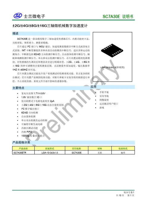
±2G/±4G/±8G/±16G三轴微机械数字加速度计内部框图(俯视图)(俯视图)可检加速度方向管脚描述电路部分设计有灵敏度(So)和零漂(Ty Off)校准补偿功能。
校准补偿的修调值保存在电路内部的NVM中。
当电路上电后,修调值被调入内部寄存器中以供正常操作补偿用。
该功能使用户无需更深层次的校准就可以使用电路。
56D/4D检测当检测到传感器处在设定的姿态产生中断,或者进入设定的姿态产生中断。
传感器在三维空间的6个状态均可独立检测。
详细设置见应用说明文档。
6自由落体检测当检测到传感器处在自由落体状态产生中断。
自由落体时,传感器质量块处于失重状态,三轴理论输出为零,传感器内置检测模块检测大三轴输出小于设定阈值则驱动中断信号产生和相应状态寄存器置位。
7睡眠和唤醒检测睡眠检测,传感器内置模块对输出值进行检测,当传感器输出值在某段时间内均无变化且输出值在设置阈值范围内,则判定传感器无动作,即置位相应状态信号和产生相应中断信号,通知MCU设置系统和传感器进入更低功耗的工作状态。
详细设置见应用说明文档。
唤醒检测,传感器内置模块对输出值进行检测,当传感器输出值超过设定阈值且达到设置时间范围,则判定传感器有动作,即置位相应状态信号和产生相应中断信号,通知MCU设置系统和传感器进入正常工作状态。
详细设置见应用说明文档。
8单击和双击检测传感器根据设定的阈值和时间判断输出值是否满足单击和双击条件,置位相应状态信号和产生相应中断信号。
详细设置见应用说明文档。
9特定词汇说明9.1灵敏度灵敏度是描述传感器增益的物理量,在此可用±1G加速度输入时能准确解析的一半最大数字输出表示。
实际测试中,通过重力加速度来测量。
将电路需要测量的轴正对地心,记录电路的输出值A1,再在这个轴线的任意平面上旋转180°,将该轴的另一端对准地心,记录电路的输出值A2。
再计算A2-A1的绝对值,绝对值除以2的结果就是该轴的灵敏度,该值随温度和时间的变化量很小。

使用说明书型跑车防护装置执行标准MT 933-2005 Q/HT 010-2007 陕西航泰电气有限公司出版日期2007-06-01目录1、概述…………………………………………………….…...…12、型号含义、工作环境条件及技术参数 (1)3、结构与工作原理 (3)4、安装与调试 (7)5、使用与操作 (14)6、常见故障和排除方法 (15)7、安全警示 (15)8、保养与维护 (15)9、安标配套件及说明 (16)10、包装与标志 (16)11、运输与贮存 (17)12、开箱检查 (17)13、订货须知 (17)1 概述根据《煤矿安全规程》第三百七十条之规定,利用先进的设计理念,开发研制出型跑车防护装置,利用高精度传感器信号作为控制挡车栏的提升、下放,实现准确车辆运行位置的确定,将挡车栏状态信息在声光监控箱上显示,显示挡车栏的提升到位、提升中、下放中、下放到位的状态指示,便于观察,以及挡车栏动作、控制故障报警,便于问题的及时发现处理,挡车栏采用吸能式结构,能有效的拦截矿井斜巷发生跑车的车辆。
装置特点(1)将先进的设计技术应用到本装置中,国内首创,使装置的寿命延长,可靠性大幅提高;(2)采用先进的PLC控制和轨道传感器测速,时间、速度测量精度高,提高了装置控制的准确度;(3)具有故障报警、挡车栏状态指示、人车和货车分别控制,功能强大,控制方便;(4)柔性减速吸能器设计,技术领先,吸能量大,使矿车的损伤程度降到了最低;(5)控制装置具有自检功能,对各部件的工作情况进行巡检,特别是对挡车栏(车挡)的位置自检,最大限度地避免了装置的误动作,对于跑车脱轨能进行有效地拦截;适用范围本装置可在煤矿、金属矿山、非金属矿山等所有倾角在30°以下的轨道提升运输斜巷中使用,对矿车运行防护。
安全标志证号:MCK0700282 型号含义、工作环境条件及基本参数型号含义Z DC最大抗冲击能量(MJ)最大巷道倾角(°)跑车防护挡车装置使用环境(1)环境温度: -20℃~+40℃;(2)相对湿度:≤96%(25℃);(3)大气压力: 80~106KPa;(4)电气设备适用于有甲烷混合物及煤尘爆炸危险的场所;(5)在无淋水、积水,无剧烈冲击和振动的地方;(6)挡车栏无防碰撞火花措施,适用于无甲烷混合物及煤尘爆炸危险的场所。
速度检测器使用简要说明1、连接线说明速度检测器内部有上下两层接线端子,上层接线端子用于连接弱电信号,下层接线端子用于强电控制输出。
将速度传感器连接在上层“传感器信号”接线端子将供电电源和硬接点控制回路连接在下层接线端子。
AC220V ---用于速度检测器供电,N表示零线,L表示火线打滑1 ----用于当前速度(或转速)为正常值的打滑率1范围的控制信号,请根据需要选择常开或常闭接点。
打滑2 ----用于当前速度(或转速)为正常值的打滑率2范围的控制信号,请根据需要选择常开或常闭接点。
打滑3 --- 用于当前速度(或转速)为正常值的打滑率3围的控制信号,请根据需要选择常开或常闭接点。
接线端接点说明NO –常开点;NC—常闭点;COM—公共点2、出厂时设置的参数(请根据现场使用需要修改)A、开机等待时间:10秒B、检测类型:转速(rpm)C、正常转速:400 rpmD、输出延时时间:5秒E、打滑率范围:0-30-50-80(打滑率3范围0-30% ;打滑率2范围30-50%;打滑率1范围:50-80%) 说明:输送机正常转速为400rpm时,打滑3继电器闭合的转速范围:0-120rpm ;打滑2继电器闭合的转速范围:120-200rpm ;打滑1继电器闭合的转速范围:200-320rpm。
3、安装将速度检测器安装在输送机从动轮附近的墙壁上,如果在室外则需要安装在具有防水功能的控制箱内,固定牢固,防止振动。
将速度检测器配套的传感器安装在从动轮侧面,并在从动轮上焊一个感应面(或则用一个螺丝帽作为感应面),传感器和感应面距离应不大于8mm,当感应面处于传感器检测范围内时,传感器动作指示灯亮,当感应面离开传感器检测范围内时,传感器动作指示灯灭。
4、连接线A、打开上盖板固定螺丝,并翻开上盖板,将传感器信号与速度检测器传感器插座可靠连接;最长引线长度不可超过10m。
B、速度检测器打滑1、打滑2、打滑3 控制端独立输出,根据实际使用的控制范围进行连接。
GSG6 矿用本质安全型速度传感器产品使用说明书山东中煤电器有限公司2012年1月5日目录1. 概述 (3)1.1 主要用途及使用范围 (3)1.2 型号组成及代表意义 (3)1.3 使用环境条件 (3)2 结构特征与工作原理 (3)2.1 结构 (3)2.2 工作原理 (4)3 技术特性 (4)3.1 产品执行标准 (4)3.2 主要性能 (4)3.3 主要参数 (4)3.4关联设备 (4)3.5尺寸重量 (4)4 安装、调试 (5)4.1 安装条件、技术要求 (5)4.2 接线 (5)图2接线图 (5)5 使用、操作 (5)6 故障分析与排除 (5)7 注意事项 (6)8 运输、贮存 (6)9 开箱及检查 (6)10 订货 (6)安装使用产品前,应详细阅读使用说明书矿用本质安全型速度传感器使用说明书1.概述1.1主要用途及使用范围矿用本质安全型速度传感器是安装在皮带运输机的机架上,测速轮与下皮带接触并检测皮带速度的传感器。
本产品使用与煤矿井下的由甲烷和煤尘爆炸性危险的环境中。
1.2型号组成及代表意义1.3使用环境条件——环境温度-5℃~40℃;——海拔高度不超过2000m;——空气相对湿度不大于95%(25℃时);——在有瓦斯、煤尘爆炸危险的场所;——在无破坏绝缘的腐蚀性气体或蒸汽的场所;——在无显著振动和冲击的场所;——污染等级为3级;——安装类别为Ⅲ类。
2结构特征与工作原理2.1结构图1 结构图2.2工作原理速度传感器滚轮上封装了磁铁,在滚轮的一侧安装有浇封的干簧管,滚轮转动带动磁铁一块转动,当磁铁接近干簧管时,导致干簧管接通。
3技术特性3.1产品执行标准本产品执行标准MT/T531-1995、GB3836-2010、Q/ZMD040-2012。
3.2主要性能3.2.1测速范围:0-6m/S。
3.2.2输出:6个脉冲/m。
3.3主要参数3.3.1 电压:DC18V;3.3.2 电流:<10mA。
Passive Speed SensorsDimensions in inches and (mm).LISTED PRODUCT Ordering Part #Thread Length (A)70085-1010-413 1.500(38.10)70085-1010-005 1.875(47.63)70085-1010-327 2.750(69.85)70085-1010-328 4.000 (101.60)70085-1010-414 6.000(152.40)Specifications:Output Voltage (Standard): 54 V (P-P)Output Voltage (Guarantee Point):13.4 V (P-P)DC Resistance: 240 ohms max.Typical Inductance: 30 mH ref.Output Polarity: White lead positiveOperating Temperature: -65 to +100°CLead Length: 10 ft (3.05 m)Housing Ground: Green/Yellow TracerNet Weight: 14 oz. max.Rating:UL and CSA listed for hazardous locations.Class I, Div 1, Groups A, B, C & D; Class II, Div 1,Groups E, F ,G. Temp Code T3C.Ordering Part #Thread Length (A)70085-1010-081 1.500(38.10)70085-1010-411 1.875(47.63)70085-1010-329 2.750(69.85)70085-1010-330 4.000(101.60)70085-1010-412 6.000(152.40)Rating:UL and CSA listed for hazardous locations.Class I, Div 1, Groups A, B, C & D; Class II, Div 1,Specifications:Output Voltage (Standard): 54 V (P-P)Output Voltage (Guarantee Point):13.4 V (P-P)DC Resistance: 240 ohms max.Typical Inductance: 30 mH ref.Output Polarity: White lead positiveOperating Temperature: -65 to 100°CLead Length: 10 ft (3.05 m)Housing Ground: Green/Yellow TracerNet Weight: 14 oz. max.Based on 8 D.P. GearGroups E, F ,G. Temp Code T3C.AI-TekInstruments,Cheshire,CTUSA UL/ATEX/CSA SensorsATEX Group II, Category 3G, Zone 2ATEX Group II, Category 3G, Zone 218Passive Speed SensorsDimensions in inches and (mm).LISTED PRODUCTOrdering Part #Thread Length (A)70085-1010-403 1.500(38.10)70085-1010-4052.75070085-1010-415 4.000(101.60)70085-1010-416 6.000(152.40)Specifications:Output Voltage (Standard): 90 V (P-P)Output Voltage (Guarantee Point): 9.4 V (P-P)DC Resistance: 750 ohms max.Typical Inductance: 210 mH max.Output Polarity: White lead positive Operating Temperature: -55 to +232° C*Mounting Thread: -0405, 3/4 - 20 UNEF-2A Cable Length:15 ft (4.57 m)Net Weight: 16 oz. max.Ordering Part #Thread Length (A)70085-1010-404 1.500(38.10)70085-1010-406 2.750(69.85)70085-1010-417 4.000(101.60)70085-1010-420 6.000(152.40)Specifications:Output Voltage (Standard): 60V (P-P)Output Voltage (Guarantee Point): 13.4V (P-P)DC Resistance: 210 ohms max.Typical Inductance: 75 mH max.Output Polarity: White lead positive Operating Temperature: -55 to +220°C Cable Length:15 ft. (4.57m)Net Weight: 16 oz. max.Based on 8 D.P. Gear*THREAD SIZEFM / ATEX SensorsTHREAD SIZE(69.85)5/8-18 UNF-2A 5/8-18 UNF-2A 5/8-18 UNF-2A 5/8-18 UNF-2A 2.750(69.85)4.000(101.60) 6.000(152.40)5/8-18 UNF-2A 70085-1010-544 1.875(47.63)70085-1010-541 1.875(47.63)3/4-20 UNEF-2A70085-1010-5423/4-20 UNEF-2A 70085-1010-5403/4-20 UNEF-2A70085-1010-5433/4-20 UNEF-2A3/4-20 UNEF-2A5/8-18 UNF-2A 5/8-18 UNF-2A 5/8-18 UNF-2ARating:FM listed Intrinsically Safe, Class I, Division 1,Groups A, B, C, D; A TEX Group II, Category 3G, Zone 2 .Rating:FM listed Intrinsically Safe,Class I,Division 1,Groups A, B, C, D; A TEX Group II, Category 3G, Zone 2 .A I -T e k I n s t r u m e n t s , C h e s h i r e , C T U S AThread Size (B)Thread Size (B)19。
淮南启航皮带速度传感器说明书摘要:1.淮南启航皮带速度传感器概述2.皮带速度传感器的工作原理3.皮带速度传感器的应用场景4.皮带速度传感器的安装与维护5.结论正文:一、淮南启航皮带速度传感器概述淮南启航皮带速度传感器是一种用于测量传送带速度的装置,能够准确实时地监测传送带上物料的流速。
该传感器广泛应用于煤矿、冶金、化工、建材等行业,为生产过程中的自动化监控和调度提供数据支持。
二、皮带速度传感器的工作原理皮带速度传感器主要由称重架、称重传感器、辊子或惰轮以及速度信号传输线等部分组成。
称重架支撑在传送带上,称重传感器通过辊子或惰轮将传送带上物料的重量转换为电信号,然后通过速度信号传输线传输到中央处理器。
中央处理器根据传送带上物料的流速和重量计算出物料的输送量,从而实现对生产过程的监控和调度。
三、皮带速度传感器的应用场景皮带速度传感器在各种行业中都有广泛应用,例如:1.煤矿:在煤矿的输送过程中,皮带速度传感器可以实时监测煤的输送速度,为矿井生产调度提供数据支持。
2.冶金:在冶金行业的轧钢和铸造过程中,皮带速度传感器可以监测钢材和金属的输送速度,以确保生产过程的顺利进行。
3.化工:在化工行业的生产线上,皮带速度传感器可以监测原料和成品的输送速度,为生产调度提供依据。
4.建筑材:在建筑材行业的混凝土搅拌和输送过程中,皮带速度传感器可以实时监测混凝土的输送速度,确保工程质量。
四、皮带速度传感器的安装与维护为了确保皮带速度传感器的准确性和稳定性,安装和维护工作十分重要。
在安装时,应将传感器安装在平整、稳定的地面上,并确保传感器与传送带之间的距离合适。
在维护时,应定期检查传感器的连接是否松动,传感器表面是否干净,以及传输线是否损坏。
如果发现问题,应及时进行处理。
五、结论淮南启航皮带速度传感器是一种重要的生产过程监测设备,能够实时准确地监测传送带上物料的流速,为生产调度提供数据支持。
****************速度设定见最后一页*******************
速度传感器SA(SC)型
使用说明书
版本号:NO1
出版日期:2006/11/2
天津华宁电子有限公司分公司
目录
1. 概述
2. 结构特征
3. 电气性能
4. 工作原理
5. 安装及使用
6. 外形尺寸及重量
7. 维护和保养
8. 包装、运输和贮存
附表一:额定速度设定表
为了保证安全并获得最佳效能,安装使用产品前,请详细阅读使用说明书并妥善保管,以备今后参考。
1.概述
·此传感器为测速传感器。
皮带额定速度由面板上的6组合拨动开关设定,额定带速设定范围从每秒0.9米到每秒6米,每0.1米为一档,共计52档。
额定速度设定地址见表1。
·输入脉冲0-96HZ,输出频率200-1000HZ。
输出频率与设定的额定皮带速度无关,输出频率仅与输入脉冲数有关。
·具有欠速和超速保护功能
2.结构特征
此模块输入输出全部隔离,内置高性能单片机。
图2-1 整体外形
图2-1 内部顶视图
1)共有六个接线端子它们是:
VIN 12V到18V电源正
GND 12V到18V电源负
KA 接点输出,速度保护时常开,速度正常时常闭
POUT+ 脉冲输出正端。
光偶三极管集电极,需要接外部电源正和上拉电阻POUT-脉冲输出负端。
光偶三极管发射极,需要接外部电源负
2)面板上K1是速度选测开关,开关打向ON位置,表示电平1,开关打向OFF位
置,
表示电平0。
D0和D5的位置如图所示。
最右边是D0。
编码选择见表1。
3)LD2是保护指示灯,在速度保护时灯灭,速度正常时灯亮。
4)速度传感器探头
红色:给速度传感器探头的电源正12-18V
黑色:给速度传感器探头的电源地
黄色:速度传感器探头的信号
3.电器特性
输入电压 +12V- +18V
输出量一路继电器开关量;一路频率量(200-1000HZ)
继电器载流≦400mA
通信接口无
正常工作功率≦0.6W
主体工作环境温度 -10 - 65摄氏度
湿度 8-80% RHG,相对凝固状态(无冷凝)
4.工作原理
速度传感器对设定的额定皮带速度的50%,70%,110%的速度段进行检测,判断是否欠速,超速。
保护范围定义如下:
●输入频率 <= (50% )Ve 或者 >= (110%)Ve 连续 2秒保护电路动作,继电器输出常开点,面板指示灯灭。
●输入频率 > (50%)Ve 并且 < (70%)Ve 连续9秒保护电路动作,继电器输出常开点。
面板指示灯灭。
●输入频率 >=(70%)Ve 与输入频率 <(110%)Ve 检测到一次认为速度正常。
继电器输出常闭合。
面板指示灯亮。
●在欠速或超速检测延时阶段,如果检测到一次正常速度,则延时时间作废,待
再次检测到欠速或超速时重新开始累计延时常数到2秒或9秒后电路保护输出。
●欠速和超速使用一个继电器接点。
●速度传感器仅仅提供速度信号,对于皮带启动和停止过程中引起的速度变化,速度传感器依然进入保护状态。
是否停机由TK200进行判别并执行。
●皮带没有转动时,速度等于0,小于额定速度的50%,速度传感器保护动作,所以皮带停转时,继电器输出常开点,面板指示灯灭。
注意:1 开关保护和频率输出是两个不同的输出方式,他们之间在输出关系中没有联系。
2 速度传感器地址设定应在没送电情况下设定,如果在运行时设定速度,应
重新上电读取新地址。
3 速度变化响应时间1秒。
5.安装及使用
设定一个额定的皮带速度,例如每秒2.4m/s,设定地址为001111。
开关位置如下:ON ■■■■
OFF ■■
6.外形尺寸及重量
重量:20公斤
7.维护和保养
◆修理时,仪表外壳和电烙铁必须接地,避免感应电压和静电损坏其它组件。
◆修理后,影响原设备的绝缘,在修理部位,涂两遍绝缘漆,以保证绝缘性能。
◆维修时更换的组件,不得改变原电路中组件的型号规格,电压,电流,功率等电气
参数。
8.包装、运输和储存
◆应在空气流通、无雨雪侵入,温度-5℃~40℃的干燥仓库中存放。
附表一:额定速度设定表。