德普施传感器使用说明书(修改)
- 格式:doc
- 大小:5.56 MB
- 文档页数:21
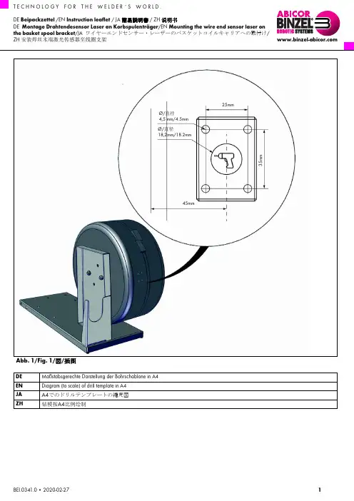
T E C H N O L O G Y F O R T H E W E L D E R ´ S W O R L D .BEI.0341.0 • 2020-02-271DE Beipackzettel /EN Instruction leaflet / JA 簡易説明書 / ZH 说明书DE Montage Drahtendesensor Laser an Korbspulenträger /EN Mounting the wire end sensor laser on the basket spool bracket /JA ワイヤーエンドセンサー・レーザーのバスケットコイルキャリアへの取付け/ZH 安装焊丝末端激光传感器至线圈支架Abb. 1/Fig. 1/図/插图DE Maßstabsgerechte Darstellung der Bohrschablone in A4EN Diagram (to scale) of drill template in A4JA A4でのドリルテンプレートの縮尺図ZH钻模按A4比例绘制25mm35m mØ/直径4,5mm/4.5mm 45mmØ/直径18,2mm/18.2mm2BEI.0341.0 • 2020-02-27Abb. 2/Fig. 2/図/插图Abb. 3/Fig. 3/図/插图123456Mounting the wire end sensor laserMounting the wire end sensor laserBEI.0341.0 • 2020-02-27 3DE1FunktionDer Drahtendesensor Laser dient zur Erfassung von metallischen Drahtwerkstoff in der Spulenaufnahme.2Montage1Bohrung gemäß Abb. 1 vornehmen.⇨Abb. 1/Fig. 1/図/插图 auf Seite 12Montage gemäß Abb. 2 vornehmen.⇨Abb. 2/Fig. 2/図/插图 auf Seite 23Technische Daten4AnschlussbilderHINWEIS•Stellen Sie die Sensitivität des Drahtendesensor Lasers nach dem Einbau ein.⇨5Einstellung Sensitivität auf Seite 4Betriebsspannung 10...30 VDC Restwelligkeit< 10% U_DC Bemessungsbetriebsstrom ≤ 100 mAAusgangsfunktion Schließer/Öffner, PNP Elektrischer Anschluss Steckverbinder M12 × 1Tab. 1Technische DatenAnschlussschemaSteckerbelegungBN (1)BK (4)WH (2)BU (3)–+2 WH1 BN3 BU4 BKMounting the wire end sensor laser5Einstellung Sensitivität⇨Abb. 3/Fig. 3/図/插图 auf Seite2HINWEIS•Nehmen Sie die Einstellung der Sensitivität (Auflösung) erst im eingebauten Zustand vor, da die Umgebung ggf.Einfluss auf die Sensitivität nehmen kann.•Vermeiden Sie metallischen Teile in unmittelbare Nähe des Drahtendesensor Lasers.•Verwenden Sie einen geeigneten Schraubendreher.Die Sensitivität wird durch Drehen des Potentiometers am Drahtendesensor Laser eingestellt. Durch Drehen im Uhrzeigersinn wird die Sensitivität erhöht und umgekehrt. Die gelbe LED am Drahtendesensor Laser leuchtet auf wenn der Draht erfasstwurde.1Nahezu aufgebrauchte Drahtspule mit wenigen Lagen Draht in Korbspulenhalter einlegen.2Sensitivität über das Potentiometer am Drahtendesensor Laser so einstellen, dass die wenigen Lagen Draht nicht mehr erfasst werden.Wird der Draht nicht mehr erfasst, leuchtet die gelbe LED nicht mehr und der Schaltpunkt für die Meldung …Drahtende“ ist eingestellt.EN1FunctionThe wire end sensor laser is used to measure metallic materials in the spool.2AssemblyNOTICE•Set the sensitivity of the wire end sensor laser after you have installed it.⇨5Setting the sensitivity on page51Drill holes as per Fig. 1.⇨Abb. 1/Fig. 1/図/插图 on page12Mount as per Fig. 2.⇨Abb. 2/Fig. 2/図/插图 on page23Technical dataOperating voltage10...30VDCResidual ripple < 10% U_DC rated operational current≤ 100 mAOutput function NO contact/NC contact, PNPElectrical connection Connector M12 × 1Tab. 2Technical data4BEI.0341.0 • 2020-02-27Mounting the wire end sensor laserBEI.0341.0 • 2020-02-27 54Figures showing connections5Setting the sensitivityAbb. 3/Fig. 3/図/插图 on page 2The sensitivity is set by turning the potentiometer on the wire end sensor laser. Increase the sensitivity by turning it clockwise. Decrease the sensitivity by turning it counterclockwise. The yellow LED on the wire end sensor laser illuminates once the wire has been measured.1Place the wire spool with just a few layers of wire left in the basket spool bracket.2Set the sensitivity via the potentiometer on the wire end sensor laser so that the few layers of wire left are no longer measured.The yellow LED is not illuminated when the wire is no longer measured and the switching point for the wire end warning is set.JA1機能ワイヤーエンドセンサー・レーザーは、コイルサポート内の金属線材の感知に使用します。


1FIGURE 1 - WHEEL SPEED SENSORS AND CONNECTORSOPERATIONThe sensor's magnet and pole piece form a magnetic field.As an exciter tooth passes by the sensor, the magnetic field is altered, which generates AC voltage in the sensor coil.Each time an exciter tooth and its adjacent space move past the tip of the sensor, an AC voltage "cycle" is generated.DESCRIPTIONThe WS-24™ wheel speed sensor is an electromagnetic device used to obtain vehicle speed information for an antilock controller. When the wheel rotates, the sensor and an exciter ring (sometimes called a “rotor” or “tone” wheel)generate a simple AC signal. This signal is sent to the controller, which analyzes the data and commands the antilock system accordingly.Specifically, the speed sensor consists of a coil, pole piece,and magnet. The exciter is a steel ring or gear-like device that has regularly spaced high and low spots called "teeth."The sensor is mounted in a fixed position, while the exciter is installed on a rotating member so that its "teeth" move, in close proximity, past the tip of the sensor.The WS-24™ sensor is available in both straight and right angle versions, to accommodate axle/wheel spacelimitations. (See Figure 1.)PREVIOUS MODEL WHEEL SPEED SENSORSThe WS-24™ sensor fit and function is compatible with all previous Bendix models.EXCITER RINGMOUNTING BLOCK WHEEL SPEED SENSORFIGURE 2 - WHEEL END ABS COMPONENTSSTRAIGHT WS-24™SENSOR90° WS-24™SENSORCONNECTORSPACKARD GT 150 SERIESPACKARD METRIPACK 150.2 SERIESDEUTSCH DTM06 SERIESPACKARD METRIPACK 280SERIES (FEMALE)PACKARD METRIPACK 280SERIES (MALE)DEUTSCH DT04SERIESSTANDARD ROUND TWOPIN2The number of AC cycles per revolution of the vehicle's wheel depends on the number of teeth in the exciter, which is programmed into the antilock controller. Using the programmed data, the controller can calculate "vehicle speed" by analyzing the frequency of AC cycles sent by the speed sensor. (The frequency of AC cycles is directly proportional to wheel speed.) See Figure 4.AC voltage is also proportional to speed, but voltage is not used to determine speed. It is only an indication of AC signal strength. The amount of AC voltage generated by a specific speed sensor depends on the distance, or "gap"between the tip of the sensor and the surface of the exciter.Voltage increases as the sensor gap decreases.Typically, the WS-24™ sensor is installed in mounting blocks that are welded to the axle housing. (See Figure 2.)WS-24™ wheel speed sensors are protected by a stainless steel sheath. They are designed to be used with beryllium-copper clamping sleeves (sometimes referred to as a “retainer bushing”, “friction sleeve” or “clip”) (See Figure 3).The clamping sleeve provides a friction fit between the mounting block bore and the WS-24™ sensor.Please note that WS-24™ wheel speed sensors must use clamping sleeve p/n 5012878 instead of p/n 5006849 (used for previous wheel speed sensors). Always use correct clamping sleeves to avoid problems associated with reduced retention force, such as sensor movement and resulting ABS trouble codes.The friction fit allows the WS-24™ sensor to "slide" back and forth under force but to retain its position when the force is removed.When the WS-24™ sensor is inserted all the way into the mounting block and the wheel is installed on the axle, the hub exciter contacts the sensor, which pushes the sensor back. Also, normal bearing play will "bump" the sensor away from the exciter. The combination of these two actions will establish a running clearance or air gap between the sensor and exciter.FIGURE 4 - SPEED SENSOR VOLTAGE CYCLE OUTPUTPEAK TO PEAKPEAK TO PEAKHIGH SPEEDLOW SPEEDTECHNICAL INFORMATIONElectrical connector 2 Pin.Sensor resistance 1500-2500 ohmsOutput voltageAt a minimum of 100Hz (approximately 7 mph) the sensor output across the leads should be 0.400 VAC.Sensor gap 0 to 0.015 inch.Sensor body Outer diameter is 0.627 inch.Normal resistance 1500-2000 Ohms.range across pins (Note: Previous model WS-20™at room temperaturesensor was rated at 2000-2500Ohms.)FIGURE 5 - TYPICAL ANTILOCK SYSTEMFIGURE 3 - CLAMPING SLEEVESP/N 5006849P/N 5012878CORRECT CLAMPING SLEEVES PREVIOUS CLAMPING SLEEVES HAVEPREVENTIVE MAINTENANCE1.Every 3 months; 25,000 miles; 900 operating hours; orduring the vehicle chassis lubrication interval, make the visual inspections noted in "SERVICE CHECKS" below.2.Every 12 months; 100,000 miles; or 3600 operatinghours, perform the OPERATIONAL TEST in this manual. SERVICE CHECKSCheck all wiring and connectors. Make sure connections are free from visible damage.Examine the sensor. Make sure the sensor, mounting bracket, and foundation brake components are not damaged. Repair/replace as necessary.WARNING! PLEASE READ AND FOLLOW THESE INSTRUCTIONS TO AVOID PERSONAL INJURY OR DEATH:When working on or around a vehicle, the following general precautions should be observed at all times.1.Park the vehicle on a level surface, apply the parkingbrakes, and always block the wheels. Always wear safety glasses.2.Stop the engine and remove ignition key whenworking under or around the vehicle. When working in the engine compartment, the engine should be shut off and the ignition key should be removed.Where circumstances require that the engine be in operation, EXTREME CAUTION should be used to prevent personal injury resulting from contact withmoving, rotating, leaking, heated or electrically charged components.3.Do not attempt to install, remove, disassemble orassemble a component until you have read and thoroughly understand the recommended procedures. Use only the proper tools and observe all precautions pertaining to use of those tools. 4.If the work is being performed on the vehicle’s airbrake system, or any auxiliary pressurized air systems, make certain to drain the air pressure from all reservoirs before beginning ANY work on the vehicle. If the vehicle is equipped with an AD-IS™ air dryer system or a dryer reservoir module, be sure to drain the purge reservoir.5.Following the vehicle manufacturer’s recommendedprocedures, deactivate the electrical system in a manner that safely removes all electrical power from the vehicle.6.Never exceed manufacturer’s recommendedpressures.7.Never connect or disconnect a hose or linecontaining pressure; it may whip. Never remove a component or plug unless you are certain all system pressure has been depleted.e only genuine Bendix® replacement parts,components and kits. Replacement hardware, tubing, hose, fittings, etc. must be of equivalent size, type and strength as original equipment and be designed specifically for such applications and systems.ponents with stripped threads or damagedparts should be replaced rather than repaired. Do not attempt repairs requiring machining or welding3unless specifically stated and approved by the vehicle and component manufacturer.10.Prior to returning the vehicle to service, make certainall components and systems are restored to their proper operating condition.11.For vehicles with Antilock Traction Control (ATC),the ATC function must be disabled (ATC indicator lamp should be ON) prior to performing any vehicle maintenance where one or more wheels on a drive axle are lifted off the ground and moving. REMOVAL1.Unplug the cable assembly connector from its lead. Liftthe lock tab and pull on the connector until it disengages.2.Gently pry the sensor and clamping sleeve from themounting block.INSPECTIONLook for any visible damage to the sensor, cable assembly, connector, mounting block, and foundation brake. Repair or replace any damaged components. Make sure the block is securely attached to the axle housing.SENSOR INSTALLATION1.For increased corrosion protection we recommend thata high-temperature rated silicon- or lithium-based greasebe applied to the interior of the mounting block, the sensor, and to a new clamping sleeve.2.Install the new clamping sleeve fully into the block, withthe retaining tabs toward the inside of the vehicle.3.Gently push (DO NOT STRIKE) the sensor into themounting block hole until it bottoms out on the face of the tone ring. Secure the cable lead wire to the knuckle/ axle housing 3-6 inches from the sensor.4.Apply a moderate amount of dielectric non-conductivegrease to both the sensor connector and harness connector.5.Engage the connectors, and push together until the locktab snaps into place.NOTE:It is important for the wheel bearings to be adjusted per the manufacturer's recommendations.Excessive wheel end play can result in antilockfunction shutdown in cases where the sensor ispushed too far away from the tone ring. ELECTRICAL TESTING1.Before testing the speed sensor, its location on thevehicle should be confirmed using the Troubleshooting or Start Up procedure for the specific antilock controllerin use. (See the Service Data Sheet for the antilock controller for this procedure.)2.Proceed to the sensor in question and inspect its wiringconnector. Disconnect the connector and test the resistance between the pins ON THE SENSOR.Normal resistance range across pins at room temperature should be 1500-2000 Ohms. (Note: Previous model WS-20™ sensor was rated at 2000-2500 Ohms.)Individually test the resistance of each pin to vehicle ground and note there is NO CONTINUITY.If the resistance readings are as shown, the wire harness leading to the modulator may require repair or replacement. Before attempting repair or replacement of the wire harness, refer to the test procedures specified for the antilock controller in use for possible further testing that may be required to substantiate the wire harness problem. If the resistance values are NOT AS STATED, replace the sensor. Resistance could be as low as 1100 Ohms or as high as 3300 Ohms if wheel end has recently been exposed to extreme temperature.OPERATIONAL TESTINGTo test sensor operation, one of two tests can be done. TEST 1Drive the vehicle in a safe area to a minimum speed of 15 mph. Be sure to apply the vehicle brakes several times. Then stop the vehicle and check the LED display on the Bendix controller. If the dash light is out and the sensor LED(s) are not illuminated, the sensor is installed properly. TEST 2Disconnect the connector from the sensor's socket or from the attached lead. Raise the vehicle wheel so it rotates easily. Connect a volt-Ohm meter (set to read Volts AC) to the pins on the sensor or lead and spin the wheel. If the wheel is spun at 1/2 revolution per second the reading should be greater than 0.250 VAC.If the sensor fails to operate as described, check the wiring from the controller to the sensor. Make sure all connectors are properly and tightly installed. Check for frayed or damaged wires and check and/or reset the sensor air gap (distance from sensor tip to exciter ring) as described in this manual. For additional troubleshooting information, see the troubleshooting procedure for the specific antilock system in use.BW2364 © 2004 Bendix Commercial Vehicle Systems LLC. All rights reserved. 9/2004. Printed in U.S.A.4。

德普施科技传感器使用说明书深圳市德普施科技有限公司SHENZHEN DEPUSH CO., LTD.1DRYB-B型应变式力传感器1.1原理与外观电阻应变计又称电阻应变片,工作原理基于导体的应变效应。
电阻应变计测量基数是利用电阻应变计测定构件表面的应变,再根据应力、应变的关系式确定构件表面应力状态的一种应力分析方法。
其测量系统可分为三个基本环节:传感器,通过零件或弹性元件将力转变为应变,再由电阻应变计将机械应变转变为电阻变化量;电阻应变仪,放大由电阻应变计组成的电桥所输出的电压,以电压或电流信号输出;指示、记录装置,可为一般指针式仪表,也可为示波器、磁带记录器或计算机,作用是对信号加以指示、记录或分析DRYB-B型力传感器就是采用电阻应变原理,将应变片电阻应变产生的效应通过测力环转换成与其成线性关系的电信号的装置。
1.2适用范围和使用场合DRYB-B型力传感器适用于各种物件质量、触力、应变等等参量的测量,结合深圳市德普施科技技术有限公司配套的实验设备,可以完成输送线实验中物件称重和转子动平衡实验中添加配重质量测量等实验内容。
1.3主要技术性能指标1.工作电压:+5V直流电压2.测量范围:0~2kg3.输出电压:0~+5V4.输出灵敏度:1.0±0.15mV/V5.测量精度:0 .03Kg6.重复性:0.02%7.工作温度:-10~+60℃8.外型尺寸:1.4 使用方法1. 将DRYB-B 型力传感器与配套载物平台装配好,并固定在磁力吸座支架或其它传感器固定支架上。
2. 将传感器的信号输出端接入配套的德普施数据采集仪A/D 通道中,传感器的信号输出采用五芯航空插头,其输出插头的连线定义如右图所示,各引脚定义为:1,输出;2,地;3,+5V 。
3. 打开数据采集仪以及DRVI 虚拟仪器平台,通过DRVI 虚拟仪器平台中的称重传感器实验脚本进行力传感器的标定,标定完毕即可进行后续的测量工作。
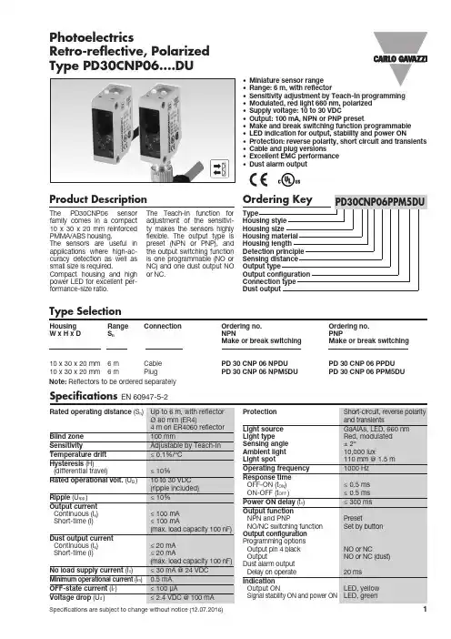
Product DescriptionThe PD30CNP06 sensor family comes in a compact 10 x 30 x 20 mm reinforced PMMA/ABS housing. The sensors are useful in applications where high-ac-curacy detection as well as small size is required. Compact housing and high power LED for excellent per-formance-size ratio.The Teach-In function for adjustment of the sensitivi-ty makes the sensors highly flexible. The output type is preset (NPN or PNP), and the output switching function is one programmable (NO or NC) and one dust output NO or NC.• Miniature sensor range • Range: 6 m, with reflector• Sensitivity adjustment by Teach-In programming • Modulated, red light 660 nm, polarized • Supply voltage: 10 to 30 VDC• Output: 100 mA, NPN or PNP preset• Make and break switching function programmable • LED indication for output, stability and power ON• Protection: reverse polarity, short circuit and transients • Cable and plug versions • Excellent EMC performance • Dust alarm outputPhotoelectricsRetro-reflective, Polarized Type PD30CNP06....DUType SelectionHousing Range Connection Ordering no. Ordering no. W x H x D S nNPNPNPMake or break switching Make or break switching10 x 30 x 20 mm 6 m Cable PD 30 CNP 06 NPDU PD 30 CNP 06 PPDU 10 x 30 x 20 mm6 mPlugPD 30 CNP 06 NPM5DUPD 30 CNP 06 PPM5DUSpecifications EN 60947-5-2Note: Reflectors to be ordered separatelyPD30CNP06....DUSpecifications (cont.)EN 60947-5-2Wiring DiagramsOperation DiagramPower supply ObjectOFF ONNot PresentPresent Operation DiagramMake Output (N.O.)Break Output (N.C.)OFF ONOFFONtv = Power ON delayDetection Diagram-300-200-10001002003000246810(m)(m m )Excess Gain1101000.1110Distance (m)E x e s s g a i nDelivery Contents• Photoelectric switch: PD 30 CNP 06 ...• Installation instruction• Mountingbracket APD30-MB1• Packaging: Cardboard boxSignal Stability IndicationPD30CNP06....DUInstallation HintsAccessoriesDimensionsAccessories• Reflector is to be purchased seperately• Mounting bracket APD30-MB2 to be purchased seperatelyFor dynamic set-up (running process)1. Line up the sensor with the reflector. Green LED is ON, status on the yellow LED is not important.2. Press the button for 3 second until both LEDs flashes simultaneously.3. Press the button a second time for at least onesecond, both LED’s flashes fast siultainiously and keep the button pressed for at least one process cycle, release the button and the sensor is ready to operate (The second switch point is stored)For make or break set-up (N.O. or N.C.)1. Press the button for 10 seconds, until the green LEDs flashes.2. While the green LED flashes, the output is inverted each time the button is pressed. Yellow LED indicates N.O. function selected.If the button is not pressed within the next 10 seconds, the current output is stored.For dust output (N.O. or N.C.)1. Press the button for 15 seconds, until the yellow LEDs flashes.2. While the yellow LED flashes, the dust output isinverted each time the button is pressed. Green LED indicates N.O. function selected.If the button is not pressed within the next 10 seconds, the current output is stored.Teach functionsNormal operation, optimized switching point.1. Line up the sensor with the reflector. Yellow LED and Green LED are ON.2. Press the button for 3 seconds until both LEDs flashes simultaneously.(The first switch point is stored)3. Place the object between the sensor and reflector in the detection zone.4. Press the button once and the sensor is ready to operate (Green LED ON, Yellow LED ON) (The second switch point is stored)For maximum sensing distance (default setting)1. Line up the sensor with the reflector, place the object between the sensor and reflector in the detection zone. Yellow LED is OFF and Green LED is ON.2. Press the button for 3 seconds until both LEDs flashes simultaneously.(The first switch point is stored)3. Press the button a second time and the sensor is ready to operate (Green LED ON, Yellow LED ON) (The second switch point is stored)For minimum detection overhead.1. Line up the sensor with the reflector. Yellow LED and Green LED are ON.2. Press the button for 3 seconds until both LEDs flashes simultaneously.(The first switch point is stored)3. Press the button a second time and the sensor is ready to operate (Green LED ON, Yellow LED ON) (The second switch point is stored)PD30CNP06....DU10 sec.Push once15 sec.Push once。

Proximity switch SDBT-MSXProximity switch SDBT-MSXCharacteristicsAtaglance• Quick and easy installation without the need to search for switching points• Mounting without accessories (power supply)• Reliable teach-in of the switching position under load during operation• Can be programmed flexibly for expanded applicationsDescriptionThe SDBT-MSX is an electronic proximity sensor for contactless feedback of the piston position of drives with magnetic proximity sensing.Additionalfeatures[X]Automatic teach-in and programmableAuto teach-in• Very easy to install without a power supply or precision adjustment. Automaticsetup during operation.• 20 mm sensing range marked on the SDBT-MSX• Mount the switch so that the end stop of the piston lies within the sensingrange• Connect SDBT-MSX to input module (PLC)• The SDBT-MSX automatically teaches in the switching point when the system isstartedProgrammable• Programmable via integrated operating button.• Switching point (alternative to auto teach-in)• Switching window range between 2 ... 15 mm• PNP/NPN• NO/NCOverview[1] Auto teach-In: the proximity switch detects the end position of the piston stroke and automatically learns the switching point during operation[2] Capacitive operating button: Programming switching point, programming PNP/NPN, programming NO/NC, programming switching window 2 15 mm[3] Cable quality energy chain + robot: 3 wire, M8 plug and open end[4] Electronic: switching output PNP/NPN, NO/NC[5] Sturdy and secure mounting with retaining screw[6] Compact, sturdy housing: 28 mm short, IP65 and IP68[7] 2 LED: teach-in display, piston within sensing range, switching output ON2d/catalogue/...– 2023/12Proximity switch SDBT-MSXCharacteristicsProductsegmentationFesto Core RangeSolves the majority of your automation tasksWith the Festo Core Range, we have selected the most important products and functions from our broad product catalogue, and added the quickest delivery.the Core Range offers you the best value with the expected high Festo quality.Quickest delivery, worldwide – wherever, whenever• Expected high Festo quality• Easy and fast to select3 2023/12 – d/catalogue/...Proximity switch SDBT-MSXType code4d/catalogue/...– 2023/12Proximity switch SDBT-MSXDatasheetGeneraltechnicaldata2) More information /catalogue/sdbt → Support/Downloads5 2023/12 – d/catalogue/...Proximity switch SDBT-MSXDatasheet6d/catalogue/...– 2023/12Proximity switch SDBT-MSX Dimensions7 2023/12 – d/catalogue/...Proximity switch SDBT-MSXDimensions8d/catalogue/...– 2023/12Proximity switch SDBT-MSX Dimensions9 2023/12 – d/catalogue/...Proximity switch SDBT-MSXDimensions10d/catalogue/...– 2023/12Ordering dataPeripheralsoverview。
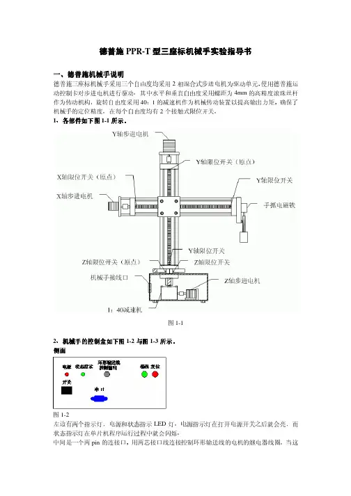
德普施PPR-T 型三座标机械手实验指导书一、德普施机械手德普施机械手说明说明德普施三座标机械手采用三个自由度均采用2相混合式步进电机为驱动单元,使用德普施运动控制卡对步进电机进行驱动。
其中水平和垂直自由度采用螺距为4mm 的高精度滚珠丝杆作为传动机构,旋转自由度采用40:1的减速机作为机械传动装置以提高输出力矩,确保了机械手的定位精度。
在每个自由度均有2个接触式限位开关。
1、各部件各部件如下图如下图1-1所示所示。
图1-12、机械手的控制盒如下图1-2与图1-3所示所示。
侧面图1-2左边有两个指示灯,电源和状态指示LED 灯。
电源指示灯在打开电源开关之后就会亮,而状态指示灯在单片机程序运行过程中就会闪烁。
中间是一个两pin 的连接口,用两芯接口线连接控制环形输送线的电机的继电器线圈。
当这个控制口有输出(高电平),环形输送线开始运行,无输出时环形输送线停止。
右边是两个按钮一个是编程,一个是复位按钮,在做编程的时候要用到。
背面左边是一个开关,中间是运动控制卡串口连接口。
图1-3背面左侧为散热风扇,右侧上方为37Pin 并口,下面为220V 交流输入接口。
3、机械手与控制盒内的运动控制卡电气连接示意图1-4机械手的X 轴步进电机接运动控制卡的步进电机4通道接口,Y 轴步进电机接运动控制卡的步进电机2通道接口,Z 轴步进电机接运动控制卡的步进电机0通道接口。
机械手手抓电磁铁的继电器线圈接运动控制卡开关量0通道输出。
环形输送线电机控制继电机线圈通过控制盒上的连接口接运动控制卡的开关量1通道输出。
各轴的限位开关的输出届运动控制卡的开关量输入。
Z 轴的限位开关接0通道和1通道,其中0通道接原点限位开关。
Y 轴的限位开关接5通道和4通道,其中5通道接原点限位开关。
X 轴的限位开关接2通道和3通道,其中2通道接原点限位开关。
串口 电源插头8路步进电机输出德普施运动控制卡接口示意图1-40通道接Z 轴步进电机2通道接Y 轴步进电机4、机械手与控制盒机械手与控制盒和环形输送线连线和环形输送线连线首先要将PPR 机械手的连线接好。

DeltaSpan™General Purpose Clean Water & Oil orPump Lift Station Pressure Level TransmitterLD31‐S1_1, LD31‐S2_1, LD32‐S1_1 & LD32‐S2_1 Series Quick StartLD31 SeriesClean Water & OilLD32 Series Pump Lift StationQS301031 Rev C©2013 Flowline, Inc.All Rights Reserved10500 Humbolt Street, Los Alamitos, CA 90720 USA Made in USATel: 562.598.3015 • Fax: 562.431.8507 • Welcome to the DeltaSpan™ Quick StartThe DeltaSpan™ Quick Start provides basic mounting, setup and use instructions for getting the DeltaSpan™ up and running quickly. If you have a non‐standard installation or setup requirement that is not addressed here, please refer to the DeltaSpan™ Manual or other support documentation located at .We Do Your Level BestThe LD31 Series DeltaSpan consists of a piezoresistive sensing element, encased in 316 SS housing. Superior lightning and surge protection utilizing dual arrestor technology, grounded to case, eliminates both power supply surges and lightning ground strike transients. Bullet nose design protects diaphragm from damage.The LD32 Series DeltaSpan consists of a piezoresistive sensing element, encased in 316 SS housing. It is perfect for wastewater and slurry applications with features to protect the unit from these demanding applications. Superior lightning and surge protection utilizing dual arrestor technology, grounded to case, eliminates both power supply surges and lightning ground strike transients. Large diameter 316 SS diaphragm seal is non‐clogging and damage resistant to floating solids.Both units come equipped with a 270‐pound tensile strength, shielded, vented cable. Ventilation tube in the cable automatically compensates for changes in atmospheric pressure above the tank. The vent tube has a filter attached to the end that will block particles, such as dust, dirt, and water droplets, from entering the tube.This Quick Start includes everything you’ll need to get the DeltaSpan up and running. For complete information, please refer to DeltaSpan documentation located at .Pressure RangesPressure Range (PSIG)Max. DistanceMeasuredIn Water Column511.54’ (3.52m)1023.09’ (7.04m)1534.63’ (10.56m)2046.18’(14.08m)Compensated Temperature RangeLD31 Series‐18° to 60° C(0° to 140° F)LD32 Series‐18° to 82° C(0° to 180° F)Current (4‐20 mA) Output OperationAn external power supply delivering 13‐30 VDC with minimum current capability of 40mA DC (per transmitter) is required to power the control loop. The Current Output diagram (above) shows the connection of the power supply, transmitter and receiver.Current OutputThe range of appropriate receiver load resistance (RL) for the DC power supply voltage available is expressed by the formula:RL Max =Vps‐13 20 mA DCShielded cable should always be used for control loop wiring.Maximum Loop Resistance is 850 ohms @ 30VDC.TroubleshootingIf you face any issues not addressed in this Quick Start, please refer to the DeltaSpan Manual located on Flowline website at .Safety ConcernWhere personal safety or significant property damage can occur due to a spill, the installation must have a redundant backup safety system installed.WarrantyFlowline warrants to the original purchaser of its products that such products will be free from defects in material and workmanship under normal use and service in accordance with instructions furnished by Flowline for a period of two years from the date of manufacture of such products. Flowline's obligation under this warranty is solely and exclusively limited to the repair or replacement, at Flowline's option, of the products or components, which Flowline's examination determines to its satisfaction to be defective in material or workmanship within the warranty period. Flowline must be notified pursuant to the instructions below of any claim under this warranty within thirty (30) days of any claimed lack of conformity of the product. Any product repaired under this warranty will be warranted only for the remainder of the original warranty period. Any product provided as a replacement under this warranty will be warranted for the full two years from the date of manufacture.ReturnsProducts cannot be returned to Flowline without Flowline's prior authorization. To return a product that is thought to be defective, go to , and submit a customer return (MRA) request form and follow the instructions therein. All warranty and non‐warranty product returns to Flowline must be shipped prepaid and insured. Flowline will not be responsible for any products lost or damaged in shipment. LimitationsThis warranty does not apply to products which: 1) are beyond the warranty period or are products for which the original purchaser does not follow the warranty procedures outlined above; 2) have been subjected to electrical, mechanical or chemical damage due to improper, accidental or negligent use; 3) have been modified or altered; 4) anyone other than service personnel authorized by Flowline have attempted to repair; 5) have been involved in accidents or natural disasters; or 6) are damaged during return shipment to Flowline. Flowline reserves the right to unilaterally waive this warranty and dispose of any product returned to Flowline where: 1) there is evidence of a potentially hazardous material present with the product; or 2) the product has remained unclaimed at Flowline for more than 30 days after Flowline has dutifully requested disposition. This warranty contains the sole express warranty made by Flowline in connection with its products. ALL IMPLIED WARRANTIES, INCLUDING WITHOUT LIMITATION, THE WARRANTIES OF MERCHANTABILITY AND FITNESS FOR A PARTICULAR PURPOSE, ARE EXPRESSLY DISCLAIMED. The remedies of repair or replacement as stated above are the exclusive remedies for the breach of this warranty. IN NO EVENT SHALL FLOWLINE BE LIABLE FOR ANY INCIDENTAL OR CONSEQUENTIAL DAMAGES OF ANY KIND INCLUDING PERSONAL OR REAL PROPERTY OR FOR INJURY TO ANY PERSON. THIS WARRANTY CONSTITUTES THE FINAL, COMPLETE AND EXCLUSIVE STATEMENT OF WARRANTY TERMS AND NO PERSON IS AUTHORIZED TO MAKE ANY OTHER WARRANTIES OR REPRESENTATIONS ON BEHALF OF FLOWLINE. This warranty will be interpreted pursuant to the laws of the State of California. If any portion of this warranty is held to be invalid or unenforceable for any reason, such finding will not invalidate any other provision of this warranty.For complete product documentation, video training, and technical support, go to .For phone support, call 562‐598‐3015 from 8am to 5pm PST, Mon ‐ Fri.(Please make sure you have the Part and Serial number available.)。
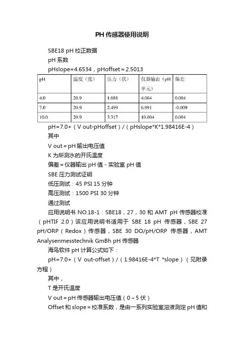
PH传感器使用说明SBE18 pH校正数据pH系数pHslope=4.6534,pHoffset=2.5013pH=7.0+(V out-pHoffset)/(pHslope*K*1.98416E-4)其中V out=pH输出电压值K为所测水的开氏温度偏差=仪器输出pH值-实验室pH值SBE压力测试证明低压测试:45 PSI 15分钟高压测试:1500 PSI 30分钟通过测试应用说明书NO.18-1:SBE18,27,30和AMT pH传感器校准(pHTIF 2.0)该应用说明书适用于SBE 18 pH传感器,SBE 27 pH/ORP(Redox)传感器,SBE 30 DO/pH/ORP传感器,AMT Analysenmesstechnik GmBh pH传感器海鸟软件pH计算公式如下:pH=7.0+(V out-offset)/(1.98416E-4*T *slope)(见附录方程)其中,T是开氏温度V out=pH传感器输出电压值(0~5伏)Offset和slope=校准系数,是由一系列实验室溶液测定pH值和输出电压值的最小二乘拟合关系确定。
其中使用了标准比测溶液的温度测量值。
这两个系数由pHFIT软件结合校准表计算得到(海鸟在设备封装中包括了校准表,该表提供了offset和slope值,被输在配置文件(.con)中)。
使用者二次校准海鸟为客户提供了校准pH传感器使用的pHFIT软件。
pHFIT是SEASOFT -DOS软件包的一部分;最新版本可以从海鸟网站下载得到。
如需要,二次校准步骤如下:1.准备一系列实验室标准测量样品(多于25个样品);保持样品大约处于同一温度,并记录。
2.记录传感器在每一个样品溶液中的输出电压值说明:对于海鸟18,27,30,测量时,要保证传感器探头前端的阳极和样品保持通电连接3.运行pHFITA.安装SEASOFT-DOS,运行pHFIT。
B.在DOS提示符下,输入传感器序列号和样品溶液温度C.在DOS提示符下,输入多于25个样品的pH值和电压值。
1Housing Rated MountingOrdering no.Ordering no.diameter operating Power MOSFET,cable Power MOSFET,plug dist.(S n )1)Make &break switching Make &break switching M302)16mm Flush (built-in)CA30CLF16CP CA30CLF16CPM6M3025mmNon-flushCA30CLN25CPCA30CLN25CPM61)Object:Grounded steel plate 2)No humidity compensationProduct DescriptionProximity Sensors Capacitive Thermoplastic Polyester Housing Type CA,M 30,2-wire AC/DC•Featuring TRIPLESHIELD™Sensor Protection•Temperature stability•Humidity compensation circuit•Adjustable sensing distance 2-16mm or 2-25mm •Rated operational voltage:20-250VAC/DC •Output:Power MOSFET•Make and break switching function,selectable •LED indication•High noise immunity•Flush and non-flush types•Cable and plug versions availableType SelectionCapacitive proximity switch-es with either sensing dis-tance 16mm flush mounted or 25mm sensing distance non-flush mounted.2-wire AC/DC output with a switchfor choosing NO and NC switching.Grey M 30polyester housing with 2m PVC cable or plug.Ideal for use in level and plastic ma-chinery applications.T R I P L E S H I E L D ™Specifications2CA,M 30,AC/DCThe environments in which capacitive sensors are install-ed can often be un stable re-garding temperature,humidity,object distance and industrial (noise)interference.Because of this,Carlo Gavazzi offers as standard features in all TRIP-LESHIELD ™capacitive sen-sors a user-friendly sensitivity adjustment instead of having a fixed sensing range,extend-ed sensing range to accom-modate mechanically demand-ing areas,temperature stability to ensure minimum need for adjusting sensitivity if temper-ature varies and high immuni-ty to electromagnetic interfer-ence (EMI).Note:Sensors are factory set (default)to maximum rated sensing range.Adjustment GuideInstallation HintsCapacitive sensors have the unique ability to detect al-most all materials,either in li-quid or solid form.Capacitive sensors can detect metallic as well as non-metallic ob-jects,however,their tradition-al use is for non-metallic materials such as:•Plastic IndustryResins,regrinds or mould-ed products.•Chemical IndustryCleansers,fertilisers,liquid soaps,corrosives and pe-trochemicals.•Wood IndustrySaw dust,paper products,door and window frames.•Ceramic &Glass IndustryRaw material,clay or finished products,bottles.•Packaging IndustryPackage inspection for level or contents,dry goods,fruits and vegetables,dairyproducts.Materials are detected due to their dielectric constant.The bigger the size of an object,the higher the density of ma-terial,the better or easier it is to detect the object.Nominal sensing distance for a capaci-tive sensor is referenced to a grounded metal plate (ST37).For additional information regarding dielectric ratings of materials please refer to Technical Information.DimensionsTypeAB C D E F SW Ømm mm mm mm mm mmCA30CLF16CP(-M6)M 30x 1.5x 50285013.615.4536CA30CLN25CP(-M6)M 30x 1.5x 50286213.615.4536Not correctCorrectThe cable should not be pulledA proximity switch should not serve as mechanical stopAny repetitive flexing of the cable should be avoided3Wiring DiagramDelivery Contents•Capacitive switch:CA30..CL...CP (-M6)•Screw driver •2nuts•Packaging:Cardboard box•Installation &Adjustment Guide (MAN CAPENG/GER)Accessories•Plugs CONH6A..serie.For further information please refer to “Accessories”.CA,M 30,AC/DC。
Manual delUsuarioSENSOR INFRARROJOPASIVO BARRAMENTODS-520 BUS Felicitaciones,usted ha adquirido un producto con la calidad JFL Alarmes, producido en Brasil con la más alta tecnología de fabricación.Este manual presenta las funciones y las características principales del equipo.ÍNDICE1 INTRODUCCIÓN (3)1.1 CARACTERÍSTICAS GENERALES (3)2 COMPONENTES PRINCIPALES (3)3 INSTALACIÓN (4)4 FUNCIONAMIENTO (4)5 PROGRAMACIÓN (4)6 RANGO DE DETECCIÓN (5)7 PRECAUCIONES/RECOMENDACIONES (6)1INTRODUCCIÓNEl DS520Bus tiene un circuito de bajo consumo de corriente administrado por un microcontrolador, que garantiza detecciones de movimiento precisas y evita disparos no deseados. La tecnología de bus combinada con la confiabilidad del algoritmo de detección preciso proporciona más seguridad al medio ambiente. Tiene un circuito de compensación de temperatura y su elemento PIR (sensor infrarrojo piroeléctrico). El sensor de bus DS 520 tiene una lente Fresnell especial, con protección contra la luz blanca y los rayos UV (ultravioleta) además de la tecnología IMMUNITY PET, es decir, no detecta animales pequeños (hasta 30 kg), como perros, gatos y ratones que eventualmente pueden circular en el área de cobertura del sensor. Estas características, junto con la tecnología de bus, hacen que el sensor de bus infrarrojo pasivo sea pionero en sensores en el mercado.1.1CARACTERÍSTICAS GENERALESDetección máxima/ángulo: 14 metros / 90º.Sensor: dos sensores piroeléctrico digital.Sensibilidad: 3 niveles de sensibilidad de detección (mínima, media, máxima);Tiempo de estabilización: 15 segundos.Tensión de alimentación: 11 a 14Vc.c..Lente: Leitosa especial PET IMMUNITY 30Kg.Consumo: 2mA.Dimensiones: 80x60x43 mm.Peso aproximado: 96 gramas.Indicación: semiabiertos.2COMPONENTES PRINCIPALESLa figura 1 presenta el sensor “abierto” y sus componentes principales: ArrayFigura 11- (- BUS +)- Conector de alimentación / comunicación2- TAMPER- Llave para protección y apertura de la tapa.3- SENSOR- Sensor piroeléctrico digital..br34-LED DISPARO(AZUL)-Encendido indica que el sensor estáactivado y transmitiendo, parpadeando alternativamente indica que el sensor se está estabilizando.5- SENSOR- Sensor piroeléctrico digital.3INSTALACIÓNInstale el sensor a una altura mínima de 2.10 metros y una altura máxima de 2.40 metros en posición vertical, sin el uso de un articulador (preferiblemente). Conecte la alimentación al sensor y espere hasta que el LED de disparo(azul)deje de parpadear.Este es un procedimiento de estabilización de circuito y dura aproximadamente1minuto.Si es necesario, ajuste la sensibilidad y el posicionamiento del sensor. Para una mejor detección, es aconsejable instalar el sensor de manera que la trayectoria del intruso sea transversal a los haces del sensor, como se muestra en la figura 2. Array Figura 24FUNCIONAMIENTOEl sensor se comunica con el panel de control a través de un solo par de cables. Al conectar el sensor al bus y programar en el panel de control, el LED permanece parpadeando hasta que el panel de control lo reconoce. Este proceso puede llevar de 10 segundos a 5 minutos.5PROGRAMACIÓNEl bus DS-520 es compatible con paneles de alarma con tecnología de bus JFL. Todos los ajustes de funcionamiento para este sensor se realizan directamente en el panel de control. Para obtener más información, consulte el manual del panel de control.Aprender y borrar: siga las instrucciones en el menú de programación del dispositivo de bus del panel de control.Sensibilidad: esta configuración se realiza en el atributo de zona del panel de control en el que se aprende el sensor. Hay tres niveles:sensibilidad de detección máxima, media o mínima.Supervisión del sensor: se puede habilitar en el menú del panel de control..br4.br 6RANGO DE DETECCIÓNLas figuras 3 y 4 a continuación muestran el rango de detección del sensor, vista superior y vista lateral.Figura 3Figura 45.br7PRECAUCIONES/RECOMENDACIONES Siga las instrucciones a continuación para evitar vacunas no deseadas.NO instale el sensor dirigido/orientado haciauna escalera cuya una mascota pueda teneracceso.NO instale el sensor dirigido/orientado hacia superficiesreflectoras, fuentes de luz infrarroja o cerca de objetos que generen cambios abrutos de temperatura como ventana,ventiladores o calefactores.NO coloque objetos o muebles con altura superior a0,8m, en el cual una mascota pueda subir (porejemplo, un gato en un sofá).NO instale el sensor en exteriores.612JFL EQUIPAMENTOS ELETRÔNICOS IND. COM. LTDARua João Mota, 471 - Jardim das PalmeirasCEP 37.540-000 - Santa Rita do Sapucaí / MGFone: (35) 3473-3550.brMANUAL DS-510 BUS REV.:04 14/07/20207ECR-18 cloud, ECR-18i cloud e ECR-18 lite rev. 00 04/05/2018。
| P500PRESSURE SENSOR DescriptionFeatures• Small Size (3/4” Hex)• External Hex for Easy Installation • Linear Amplified Output • Temperature Compensated • Superior Long-Term Stability • Low Power Consumption• Minimum Life Expectancy: Ten Million CyclesThe P500 incorporates Kavlico’s 4th generation ceramic capacitive sense element with the latest state of the art proprietary ASIC. Available in brass or stainless steel housings, this multi-purpose sensor is rugged by design. Highly reliable, the P500 is ideal for measuring a broad range of process media including hydrocarbon based fluids, air, and gases. The P500 package has a built-in Metri-Pack 150 series sealed electrical connector and is available with popular pressure connection thread options. The sensor is offered with seal materials suitable for diverse applications. Standard pressure ranges are available in PSI or Bar.Applications• Compressors • Process Controls• Instruments & Test Equipment • Sterilizers • Air Pressure• Oil & Fuel Pressure • Coolant Pressure• Agricultural Equipment• CNG & Natural Gas EnginesSPECIFICATIONSTECHNICAL SPECIFICATIONSPressure RangesPhysicalPerformanceElectricalPART NUMBER DESIGATION: P500-300-S-E 4 AVoutputN/CVsupplyGNDVENT HOLE (GAUGE)USE STANDARD OPENEND WRENCH OR SPECIALIZED SOCKET WRENCH ONLY19.1818.69.755.736HEXDATE CODE EXAMPLE: L0515UL LOGO (PRESSURE DEPENDENT)KAVLICO PART #(SEE EXAMPLE)PERMANENTLY IDENTIFY X X X X XDATE CODE11P500-XXX-X-X4XSHOWN19.09 1.575 MAX.752405.59.220Dimensions in mm [Inch]DIMENSIONSPressure Sensor with Electrical ConnectionPressure Connections and Recommended Installation Torque1/4 - 18 NPT 1/8 - 27 NPT Stud EndDIN 3852-B-G1/4External External External 25 Nm20 Nm20 NmTapped Hole DIN 3852-Y-G1/43/8-24 UNF-2A PER SAE J 1926/23/8-24 UNF-2B PER SAE J 1926/1Internal External Internal 15 Nm22 Nm22 NmPage 4CONTACT USAmericas+1 (800) 350 2727***************************************Europe, Middle East & Africa +359 (2) 809 1826****************************Asia Pacific*************************.com China +86 (21) 2306 1500Japan +81 (45) 277 7117Korea +82 (31) 601 2004India +91 (80) 67920890Rest of Asia +886 (2) 27602006 ext 2808Sensata Technologies, Inc. (“Sensata”) data sheets are solely intended to assist designers (“Buyers”) who are developing systems that incorporate Sensata products (also referred to herein as “components”). Buyer understands and agrees that Buyer remains responsible for using its independent analysis, evaluation and judgment in designing Buyer’s systems and products. Sensata data sheets have been created using standard laboratory conditions and engineering practices. Sensata has not conducted any testing other than that specifically described in the published documentation for a particular data sheet. Sensata may make corrections, enhancements, improvements and other changes to its data sheets or components without notice.Buyers are authorized to use Sensata data sheets with the Sensata component(s) identified in each particular data sheet. HOWEVER, NO OTHER LICENSE, EXPRESS OR IMPLIED, BY ESTOPPEL OR OTHERWISE TO ANY OTHER SENSATA INTELLECTUAL PROPERTY RIGHT, AND NO LICENSE TO ANY THIRD PARTY TECHNOLOGY OR INTELLECTUAL PROPERTY RIGHT, IS GRANTED HEREIN. SENSATA DATA SHEETS ARE PROVIDED “AS IS”. SENSATA MAKES NO WARRANTIES OR REPRESENTATIONS WITH REGARD TO THE DATA SHEETS OR USE OF THE DATA SHEETS, EXPRESS, IMPLIED OR STATUTORY, INCLUDING ACCURACY OR COMPLETENESS. SENSATA DISCLAIMS ANY WARRANTY OF TITLE AND ANY IMPLIED WARRANTIES OF MERCHANTABILITY, FITNESS FOR A PARTICULAR PURPOSE, QUIET ENJOYMENT, QUIET POSSESSION, AND NON-INFRINGEMENT OF ANY THIRD PARTY INTELLECTUAL PROPERTY RIGHTS WITH REGARD TO SENSATA DATA SHEETS OR USE THEREOF.All products are sold subject to Sensata’s terms and conditions of sale supplied at SENSATA ASSUMES NO LIABILITY FOR APPLICATIONS ASSISTANCE OR THE DESIGN OF BUYERS’ PRODUCTS. BUYER ACKNOWLEDGES AND AGREES THAT IT IS SOLELY RESPONSIBLE FOR COMPLIANCE WITH ALL LEGAL, REGULATORY AND SAFETY-RELATED REQUIREMENTS CONCERNING ITS PRODUCTS, AND ANY USE OF SENSATA COMPONENTS IN ITS APPLICATIONS, NOTWITHSTANDING ANY APPLICATIONS-RELATED INFORMATION ORDERING OPTIONSP500 Sensor, 0 - 16 Bar Absolute, Fluorosilicone Seal Material, 1/4 - 18 NPTA: With Mating Connector, w/12”, 18 AWG Leads C: Without Mating ConnectorAGENCY APPROVALS & CERTIFICATIONSEN 61326-1, 2006IEC 61000-4-2, 2001IEC 61000-4-3, 2006IEC 61000-4-8, 20012002/95/EC RoHS Directive File # SA10552。
I NSTRUCTION M ANUALSENSOPTIC FIBER-OPTIC DISPLACEMENT TRANSDUCERModel FODRoctest Limited, 2000. All rights reserved.This equipment should be installed and operated only by qualified personnel. Its misuse is potentially dangerous. The Company makes no warranty as to the information furnished in this manual and assumes no liability for damages resulting from the use thereof. The information herein is subject to change without notification.Tel.: 1.450.465.1113 • 1.877.ROCTEST (Canada, USA) • 33.1.64.06.40.80 (France) • 41.91.610.1800 (Switzerland)E10169-001109TABLE OF CONTENTS1PRODUCT (1)1.1GENERAL (1)1.2DESCRIPTION (1)1.3CALIBRATION (2)1.4SPECIFICATIONS (2)2READING PROCEDURE (3)2.1INITIAL READINGS (3)2.2DISPLACEMENT EQUATION (3)2.3INTERPRETATION (3)3INSTALLATION (4)4CABLE (4)1 PRODUCT1.1 GENERALThe fiber-optic displacement transducer is used to measure movements such as: ∙The opening or closing of construction joints in buildings, bridges and pipelines ∙The amount of opening or contraction of joints in concrete structures∙Joint and crack openings within rock and concrete masses or at rock-concrete interfaces.The FOD is supplied with either an embedment type or surface-mounted installation fixture.All Roctest fiber optic readout equipments can read the FOD. Data acquisition systems are also available. Contact manufacturer for more details.The FOD is delivered with a calibration data sheet providing calibration factors to be used in the displacement equation. The displacement equation converts readings units into engineering units. The calibration factors are determined by factory calibration.1.2 DESCRIPTIONOur unique design is based on a Thin Film Fizeau Interferometer device (TFFI) mounted on a movable shaft. The TFFI can be seen as a spatially distributed Fabry-Perot cavity where the cavity length varies along the lateral position. The optical fiber is mounted in a manner that the tip is facing the surface of the TFFI, which is moved relative to the optical fiber extremity. By connecting this device to one of Roctest’s white-light fiber-optic readout unit, it becomes an absolute position and displacement transducer.The FOD is totally immune to electromagnetic and radiofrequency (EMI/RFI) interferences and carries no risk of current leakage or ignition. The FOD can be packed in a very compact form and can be located far away (up to 2 km) from the readout unit. These characteristics make the FOD well suited for difficult-to-reach locations and hazardous environments such as those containing explosive materials.The surface-mounted FOD is available in two models: FOD-F and FOD-J. The FOD-F is mounted on an anchor block. Its loaded-spring spindle remains continuously in contact with an anchored reference surface.Model FOD-FWith the FOD-J confiuration, both extremities are fixed to ball joint linkages that mate with the anchors. This model is fited with a telescopic plunger free to move in or out of the housing as the distance between the measurement points varies. The FOD-J allows for small latteral displacements.Model FOD-JBoth configurations are available with groutable or expansion anchors.1.3 CALIBRATIONAll displacement transducers are individually calibrated before shipment.A calibration sheet, supplied with each gage, included the following informations:∙The serial number∙The temperature during the calibration∙The calibration factors: A, B, C, D, E∙The conversion equation∙The fiber optic cable type and its length1.4 SPECIFICATIONSLinear Stroke: 20 mmAccuracy: ±0.1% of F.S.Resolution: 0.002 mmEMI/RMI susceptibility: Intrinsic immunityCable length: 1.5 meter length. Custom length up to 2 km and hightemperature cable availableCable material: 4.0 mm O.D.polyurethane jacket (other material available) Housing material: Aluminum or stainless steelConnector: STDimensions: 144 mm length x 19 mm O.D. (other size optionally available)2 READING PROCEDURE2.1 INITIAL READINGSGage readings should be taken as soon as the gages are received to ensure that they have not been damaged during shipment. Please review the readout unit instruction manual before proceeding with the reading.Before a transducer can be used with the fiber-optic readout unit from Roctest, its gage factor (0001000) must be first selected. The gage factor, already recorded in the memory of the readout unit, is registered on a label installed on the cable close to the fiber-optic connector and on the calibration sheet of the gage.After that, readings displayed be the readout can be read and used it in the equation supplied on the calibration data sheet to obtain the displacement in engineering units. Steps before taking a reading1. Select gage factor (0001000) in the readout memory2. Associate gages to appropriate channel number and gage factor3. Be sure that you have the displacement equation and the calibration factorsappropriate to each gage.2.2 DISPLACEMENT EQUATIONThe reading value on the readout unit must be converted in engineering unit such as millimeter (mm) or inch (in) by the displacement equation supplied on the calibration data sheet. The equation is:Di = A L4 + B L3 + C L2 + D L + E (1) where: Di = DisplacementA,B,C,D,E = Calibration factors given on the calibration data sheetL = Current reading in unit2.3 INTERPRETATIONThe reading seen on the readout unit is the distance between the actual point and the reference point (located at mid-range) established during factory calibration. Therefore, it is necessary to fix your own reference point by taking an initial reading after installation is completed. The initial displacement (D0), calculated with equation 1, gives your reference displacement. Then you can compare the following reading (D1) to the reference and compute the real displacement (D real).The following equation indicates how to calculat real displacement.D real= D1–D0 (2) Note:A positive value of D real indicates an increasing displacement (extension of shaft) and a negative value indicates a decreasing displacement or contraction.3 INSTALLATIONPrior installation of the fiber optic displacement transducer, a starting point must be determined. This position must be:∙Mid-range : to measure extension or contraction∙End of range (shaft in complete extension): to measure mostly contraction∙Beginning of range: to measure mostly extension4 CABLEThe gage factor and the serial number corresponding to each FOD are stamped on a tag fastened to the readout end of the cable. In option, the serial number is stamped along the entire length of the cable. Should the cable be cut, we recommend the use of our cable splice kits. Call the manufacturer for details.。
RequestEnsure that this Instruction Manual is delivered tothe end users and the maintenance manager.- Safety section-This Safety section should be read before starting any work on the relay.Be sure to read the instruction manuals and other related documents prior to commencing any work on the relay in order to maintain them in a safe condition.Be sure to be familiar with the knowledge, safety information and all caution items of the product prior to use.Caution means that failure to observe safety information, incorrect use, orimproper use may endanger personnel and equipment and causepersonnel injury or physical damage.I tems as classified to the caution may become to occur more sever results according to the circumstance. Therefore, all items described in the safety section are important and to be respected without fail.-Avoid to be exposed to unusual shock, vibration, leaning or magnetic field-Not expose to harmful smoke, gas, salty air, water, vapor, dust, powder, explosive material, wind or rain.(2) Qualified personnel may work on or operate this product, otherwise, the product performance/life might beunfavorably affected and/or burning or erroneous operation might occur.(3) Be sure to read and understand the instruction manuals and other related documents prior to commencingoperation and maintenance work on the product. Otherwise, electrical shock, injury, damage, or erroneous operation might occur.(4) While energizing product, be sure not to remove any unit or parts without permissible one. Otherwise, damage,or erroneous operation might occur.(5) While energizing product, be sure to make short circuit of current transformer secondary circuits before settingchange or drawing out the sub unit. Otherwise, secondary circuit of live current transformer might be opened and damage or burning might occur due to the high level voltage.(6) While energizing product, be sure to open trip lock terminal before setting change or drawing out the internalunit of product. Otherwise, erroneous operation might occur.(7) Be sure to use the product within rated voltage and current.Otherwise, damage or erroneous might occur.5. Items concerning maintenance and checking(1) Be sure that only qualified personnel might work on or operate this product.Otherwise, electrical shock, injury, damage, or erroneous operation might occur.(2) Be sure to read and understand the instruction manuals and other related documents prior to commencingoperation and maintenance work on the product. Otherwise, electrical shock, injury, damage, or erroneous operation might occur.(3) In case of replacing the parts, be sure to use the ones of same type, rating and specifications, etc.If impossible to use above parts, be sure to contact the sales office or distributor nearest you.Otherwise, damage or burning might occur.(4) Testing shall be done with the following conditions.-Ambient temperature: 20℃±10℃-Relative humidity: Less than 90%-Magnetic field: Less than 80A/m-Atmospheric pressure: 86~106×103 Pa-Installation angle: Normal direction±2°-Deviation of frequency: within ±1%of nominal frequency-Wave form(in case of AC): Distortion factor less than 2%(Distortion factor=100%×effective value of harmonics/effective value of fundamental)-Ripple (in case of DC): Ripple factor less than 3%(Ripple factor=100%×(max-min)/average of DC)(5) Deviation of auxiliary power: within ±2% of nominal voltage(6) Be sure not to inject the voltage or current beyond the overload immunity.Otherwise, damage or burning might occur.(7) Be careful not to touch the energized parts.Otherwise, the electric shock might occur.(8) While energizing product, be sure not to clean up the product . Only wiping a stain on the front cover of productwith a damp waste might be allowable. (Be sure to wring hardly the water out of the waste.)6. Items concerning modification and/or repair workBe sure to ask any modification and/ or repair work for product to the sales office or distributor nearest you.Unless otherwise, any incidents occurred with modification or repair works (including software) done by any other entity than MITSUBIHI ELECTRIC CORPORATION shall be out of scope on warranty covered by MITSUBISHI ELECTRIC CORPORATION.7. Items concerning disposalParticular regulations within the country of operation shall be applied to the disposal.- Guarantee -1.Guarantee periodThe guarantee period of this product should be one year after delivery, unless otherwise specified by both parties.2.Scope of guaranteeWhen any fault or defect is detected during the period of guarantee and such fault or defect is proved to be caused apparently at the responsibility of MITSUBISHI ELECTRIC CORPORATION, the defective unit concerned will be repaired or replaced bya substitute with free of charge. However, the fee for our engineer dispatching to site has to be covered by the user. Also, siteretesting or trial operation caused along with replacing the defect units should be out of scope of our responsibilities. It is to be acknowledged that the following faults and defects should be out of this guarantee.① When the faults or defects are resulted from the use of the equipment at the range exceeding the condition/environmentrequirements stated in the catalogue and manual.② When the faults or defects are resulted from the reason concerning without our products.③ When the faults or defects are resulted from the modification or repair carried out by any other entity than MITSUBISHIELECTRIC CORPORATION.④ When the faults or defects are resulted from a phenomenon which can not be predicted with the science and technologyput into practical use at the time of purchase or contract.⑤ In case of integrating our products into your equipment, when damages can be hedged by the proper function or structurein the possession of your equipment which should be completed according to the concept of the de fact standard of industry.⑥ In case of that the faults or defects are resulted from un-proper application being out of instruction of MITSUBISHIELECTRIC CORPORATION.⑦ In case that the faults or defects are resulted from force majeure such a fire or abnormal voltage and as an act of God suchas natural calamity or disaster.3.Exclusion of loss in opportunity and secondary loss from warranty liabilityRegardless of the gratis warranty term, MITSUBISHI ELECTRIC CORPORATION shall not be liable for compensation of damages caused by any cause found not be the responsibility of MITSUBISHI ELECTRIC CORPORATION, loss in opportunity, lost profits incurred to the user by failures of MITSUBISHI ELECTRIC CORPORATION products, special damages and secondary damages whether foreseeable or not, compensation for accidents, and compensation for damages to products other than MITSUBISHI ELECTRIC CORPORATION products and other tasks4.Applications of products①The user is requested to confirm the standards, the regulations and the restrictions which should be applied, in case ofutilizing products described in this catalogue and another one in combination.Also, the user is requested to confirm the suitability of our products to your applied system or equipment or apparatus by yourself. MITSUBISHI ELECTRIC CORPORATION shall not be liable for any suitability of our products to your utilization.②This MITSUBISHI ELECTRIC CORPORATION products described in the catalogue have been designed and manufacturedfor application in general industries, etc. Thus, application in which the life or an asset could be affected, such as medical system for life-sustaining, in nuclear power plants, power plants, aerospace, and transportation devices(automobile, train, ship, etc )shall be excluded from the application. In addition to above, application in which the life or an asset could be affected by potentially chemical contamination or electrical interference and also in which the circumstances and condition are not mentioned in this catalogue shall be excluded.Note even if the user wants to use for these applications with user’s responsibility, the user to be requested to approve the specification of MITSUBISHI ELECTRIC CORPORATION products and to contact to the technical section of MITSUBISHI ELECTRIC CORPORATION prior to such applications. If the user applies MITSUBISHI ELECTRIC CORPORATION products to such applications without any contact to our technical section, MITSUBISHI ELECTRIC CORPORATION shall not be liable for any items and not be insured, independently from mentioned in this clause.③In using MITSUBISHI ELECTRIC CORPORATION product, the working conditions shall be that the application will not leadto a major accident even if any problem or fault occur, and that backup or duplicate system built in externally which should be decided depend on the importance of facility, are recommended.④The application examples given in this catalogue are reference only and you are requested to confirm function andprecaution for equipment and apparatus and then, use our products⑤The user is requested to understand and to respect completely all warning and caution items so that unexpected damagesof the user or the third party arising out of un-correct application of our products would not be resulted.5.Onerous repair term after discontinuation of product①MITSUBISHI ELECTRIC CORPORATION shall accept onerous product repairs for 7(seven) years after production isterminated. (However, please consider the replacement of products being in operation during 15 years from ex-work.)②Product supply (including repair parts) is not available after production is discontinued.6.Changes in product specificationThe specification given in the catalogue, manuals or technical documents are subject to change without prior to notice. 7.Scope of serviceThe technical service fee such as engineer dispatching fee is excluded in the price of our products. Please contact to our agents if you have such a requirement.MUV-A1 Series Under Voltage [Standard JEC 2511] Feature1.A digital under voltage relay, which has high accuracy and operating characteristic.2.High reliability by the self-monitoring function.The relay monitors control circuit, electric circuit and program data at all time, which are indicated by the (LED “RUN” lights up in the normal condition and goes out in the abnormal condition.)3.Enriched measurement and display functions.It is available to measure the input value of voltage and display the pick-up and setting values. 4.Forced operating is available by a test button. 5.Not need outside auxiliary power supply.The auxiliary power supply can be supplied by VT secondary.6.High vibration and impulse resisting performance. 7.During the under voltage, the output contacts (b contact) continuously close.Rating and SpecificationsType Name MUV-A1V-R MUV-A1V-RD Style No. 094PGA 513PGA Protection Under voltage element×1 ElementMeasure VoltageVoltage AC100VRatingsFrequency 50/60HZ(changeover)Voltage Lock-60-65-70-75-80-85-90-95-100VTime 0.1-0.2-0.5-1.0-1.5-2.0-2.5-3.0-4.0-5.0s SettingsUsing condition Frequency:50Hz(SW1-ON)/60Hz(SW1-OFF) (changeover)Self-monitor The LED“RUN”(green) lights up in normal condition.Operation display The operation target turns from black into orange color when relay operates.(Manual resetting type)DisplayNumericaldisplay SW No. Indication function 0 Voltage measurement(V) :55~130 1 Pickup display :U.2 Voltage setting(V) :Lo,60~1003 Time setting(s) :0.1~5.0 4 Frequency setting(HZ) :50,60Test button Forced operation is available in the condition of the rated voltage being applied.(The button should be depressed as long as the desired operation time lasts)Power Consumption VA(VT)Normal:7VA Operating:5VACase Compact cylindrical fixed type(Fig.16-1)Compact cylindrical draw-out type(Fig.16-2)Mass Approx. 1.1kg Approx. 1.2kg“Lock” means that to let this element not to operate.Characteristicsabnormality.・Between VT secondary and ground(E terminal)・Between auxiliary power supply contacts and ground (E terminal) ・Between auxiliary power supply contactsRadio disturbance Apply 110% input voltage of operating value to the relay with maximum voltage setting. At the same time to put a transceiver antenna (5W output) with 150MHz or 400MHz band closing the relay panel about 0.5m.It is not abnormal operation.Contact capacity Closed circuitAC110V:10A(Power factor = 0.5)DC220V:10ADC110V:15A(L/R=0s)Opened circuitAC110V:5A(Power factor = 0.5)AC220V:1A(Power factor = 0.5)DC110V:0.2A(L/R=40ms)Internal connection diagramOperating Description1.Relay Function①This relay has a built-in regulated voltage circuitwhich derivers control voltage from the VT secondary voltage, therefore, particular auxiliary power supply is not required.②The input voltage is converted into a electroniccircuit level signal by a built-in auxiliary VT.③The input voltage signal is converted into a digitalsignal by A/D converter, and as data input microcomputer.④The microcomputer calculates and compares the level ofthe input voltage signal data with the setting value data.If the voltage signal falls below the setting value, the timer starts counting. If the counter is more than the operating time setting, the relay and the operating flag unit start to operate.2.RUN Indication(Self-monitoring Function)This relay monitors control voltage, electric circuitand program data at all time. The RUN LED (green)lights up in the normal condition, and goes out in theabnormal condition. Since control voltage is derived from VT secondary voltage input, the LED goes out when the control voltage lower than approx. 50V.3.Numerical Display FunctionBy changing the position of the selector switch, the following values can be displayed on the numerical display LED.①Voltage measurement…(switch position:0)…Based on the voltage signal data, the voltage is measured and computed, and then to display the input voltage value.The display range is from 55V to 130V.(When less than 55V, nothing be displayed. When more than 130V, “O.F.” is displayed.)②Pickup display…(switch position:1)…When the input voltage is less than the setting value,U.is displayed.Using this function, easy test the operating value.When pressing the TEST button (forced operation),U. is displayed.③Setting value display…(Switch position:2~4)…This function displays the relay setting condition including the voltage settings(V), operating time T settings (s) and frequency setting value (Hz).External Connection Diagram (Example)Handing Method1.Panel assemble①Do connect the relay terminal “E” to earth at Class D please.②Type MUV-A1V-RD is a draw-out type that the sub-unit can be drawn out from case.For detail, refer to section of “Drawing out and Housing operation of Sub-unit” please.2.Use and Operation①About the setting of frequency, it is set OFF at the time of shipment, so it is necessary to set the frequency switch again according to the using frequency when begin to use this relay.Refer to the page 14, Cover Handling.②Avoid changing the setting value during relay operating, since it is possible to occur unwanted operation. However, if the setting change is unavoidable, please push up the reset lever in order to lock relay operating. ③To change the setting may be realized manually by the setting switch. It is also possible by using a smallminus (-) screwdriver. If a large minus (-) screwdriver is used, it may damage the groove of the switch knob. ④The switch for setting is a rotary one utilizing snap action. When the setting is changed, turn the switch smoothly so as not to stop it in mid-position. ⑤The position of the display selector switch is not specified in particular, but if it is normally set toThe input voltage value can be measured conveniently.⑥Since the RUN indicator LED is lighting during the normal operation, check it in routine checking please. If it turns off, check input voltage value at first, and if it is still in OFF state even the input voltage is approx 50V or more, please contact our local agent and branch office since the relay may fail.TestA relay test is carried out sufficiently by maker before shipment. But at the following cases, it is recommended thatthe test be carried out again.a. After the products are unpacked when receivedb. When the equipment starts operation(Power receiving starts)c. When periodical checkup is carried out(Normally once per year)1.Testing①MUV-A1 type under voltage relay is a digital relay, itis available to test it like as other one-function relay.②About the voltage input waveform, please use a sine wavewithout distortion.③To select the switch for each setting with hand or usea small regular screwdriver (“-” type).as appropriate according to the test item. Set other switches for setting according to the test conditions of the operation characteristic control points.⑤If the operation characteristics are tested speciallyin individual control points (for example, when tested with the in-service setting conditions), the test should be performed with the operation characteristic points when the products are received, a receiving test should be carried out with individual control point after judging the performance of this relay. Please use this data as a later standard.2.W ithstand Voltage TestPerform the unit test as follows.a. Apply 2000V AC (commercial frequency)between allelectric circuits and case (E terminal) for one minute, and make sure that no problem.b. Apply 2000V AC (commercial frequency)between allelectric circuits and case (E terminal) for one minute,3.Operation Characteristic Test①Increase the control voltage gradually, the RUNindicator LED (green) will light up at approx. 50V.This indicates that the electronic circuit has started to operate normally.② With the rated voltage and press the TEST button locatedrelay panel, make sure that the forced operation is available please.4.Operation Characteristic Control Point Perform the test periodically according to the following Test condition and criterion.Test ConditionsTest itemInputOperationValueOperationTimeCriterionOperationValue―EachsettingMinimumsetting±5% ofsetting value ResetValue―MaximumsettingMinimumsetting105% or lessof operatingvalueMaximumsettingMinimumsettingSetting value±20ms OperationTimeRatedvoltage↓70% ofsettingMaximumsettingOther thanthe above±10% ofsetting valueTerminal LayoutDrawing out and Housing operating of Sub-unit― For compact cylindrical draw-out type(RD type) It is available to draw-out the sub-unit from the relay case instead of removing the external wires. So that easier to carry out checking and testing.When drawing out housing, please pay attention to not to touch the electric circuit and move the sub-unit by Handing the lever or from. Otherwise, it is possible to get an electric shock or make internal electric parts damage. The following operation should be checked when sub-unit be drawn out from relay case.・ Lock the tripping circuit・ Turn off the power supply into relay ・ Disconnect VT circuit・ Open the auxiliary power supply (only the RD type relay)Monitoring and DimensionsImprovement on the reliability of protection functionAny parts and materials applied to the protection relay have limited life time which will bring the degradation to the relay.The degree of degradation will be variable and depend on the purpose, period in use, applied circumstance and unevenness on the performance of each part.MITSUBISHI ELECTRIC CORPORATION design the relay so as to realize that the recommended replaced duration is more them 15 years.However, there may be some possibilities to occur some defects before reaching 15 years due to above mentioned the degree of degradation of parts and materials being depended on the condition in use.To prevent unwanted operation or no operation of relay due to above reasons, it is recommended to apply the relay with self-diagnosis function and/or multiplexing relay system such as dual or duplex scheme.HEAD OFFICE: 7-3 MARUNOUCHI 2-CHOME, CHIYODA-KU TOKYO, 100-8310, JAPAN。
德硕瑞环形传感器说明书senstime摘要:一、德硕瑞环形传感器简介1.产品背景2.产品特点3.适用范围二、环形传感器的安装与使用1.安装前的准备2.安装步骤3.使用方法三、环形传感器的参数与性能1.技术参数2.性能指标3.工作原理四、环形传感器的维护与故障排除1.日常维护2.常见故障及解决方法3.注意事项五、环形传感器的应用案例1.实际应用场景2.效果与优势正文:【德硕瑞环形传感器说明书】一、德硕瑞环形传感器简介德硕瑞环形传感器是一款高性能的传感器产品,具备高精度、高稳定性、高可靠性等特点,广泛应用于各种环境监测和控制领域。
本说明书将为您介绍德硕瑞环形传感器的安装、使用、参数、维护及应用案例等方面的内容,帮助您更好地了解和使用该产品。
二、环形传感器的安装与使用1.安装前的准备在安装环形传感器之前,请确保电源、信号、通讯线缆等已经准备就绪,并确保传感器所处的环境中无腐蚀性、无导电尘埃、无导电液体等对传感器造成损害的物质。
2.安装步骤(1)根据安装需求,选择合适的安装位置。
(2)将环形传感器的底座安装在所需位置,并确保底座水平。
(3)将传感器主体安装到底座上,并确保连接紧密。
(4)接通电源、信号、通讯线缆,检查连接是否牢固。
3.使用方法(1)接通电源,待系统自检完成后,环形传感器将自动开始工作。
(2)通过通讯接口与上位机连接,可实时接收和发送数据。
(3)根据需要设定传感器的工作参数,如测量范围、采样周期等。
三、环形传感器的参数与性能1.技术参数(1)测量范围:根据具体型号而定。
(2)测量精度:±0.1%。
(3)采样周期:可调。
(4)信号输出:标准信号输出。
2.性能指标(1)高精度:具备高精度的测量能力,满足高精度控制需求。
(2)高稳定性:在各种环境下都能保持稳定的测量性能。
(3)高可靠性:采用高品质材料和制造工艺,确保产品长期稳定运行。
3.工作原理环形传感器通过测量电磁波在环形传感器内部的传播时间,从而计算出被测物体的距离、速度等信息。
德普施科技传感器使用说明书深圳市德普施科技有限公司SHENZHEN DEPUSH CO., LTD.1DRYB-B型应变式力传感器1.1原理与外观电阻应变计又称电阻应变片,工作原理基于导体的应变效应。
电阻应变计测量基数是利用电阻应变计测定构件表面的应变,再根据应力、应变的关系式确定构件表面应力状态的一种应力分析方法。
其测量系统可分为三个基本环节:传感器,通过零件或弹性元件将力转变为应变,再由电阻应变计将机械应变转变为电阻变化量;电阻应变仪,放大由电阻应变计组成的电桥所输出的电压,以电压或电流信号输出;指示、记录装置,可为一般指针式仪表,也可为示波器、磁带记录器或计算机,作用是对信号加以指示、记录或分析DRYB-B型力传感器就是采用电阻应变原理,将应变片电阻应变产生的效应通过测力环转换成与其成线性关系的电信号的装置。
1.2适用范围和使用场合DRYB-B型力传感器适用于各种物件质量、触力、应变等等参量的测量,结合深圳市德普施科技技术有限公司配套的实验设备,可以完成输送线实验中物件称重和转子动平衡实验中添加配重质量测量等实验内容。
1.3主要技术性能指标1.工作电压:+5V直流电压2.测量范围:0~2kg3.输出电压:0~+5V4.输出灵敏度:1.0±0.15mV/V5.测量精度:0 .03Kg6.重复性:0.02%7.工作温度:-10~+60℃8.外型尺寸:1.4 使用方法1. 将DRYB-B 型力传感器与配套载物平台装配好,并固定在磁力吸座支架或其它传感器固定支架上。
2. 将传感器的信号输出端接入配套的德普施数据采集仪A/D 通道中,传感器的信号输出采用五芯航空插头,其输出插头的连线定义如右图所示,各引脚定义为:1,输出;2,地;3,+5V 。
3. 打开数据采集仪以及DRVI 虚拟仪器平台,通过DRVI 虚拟仪器平台中的称重传感器实验脚本进行力传感器的标定,标定完毕即可进行后续的测量工作。
1.5 注意事项1. 不要带电插/拔传感器,以免损坏调理电路。
2. 不要长期过载使用,否则降低该传感器的使用寿命。
3. 测力环结构,双面都贴有应变片,双面应变片特性不同,使用时注意正确判断拉压方向。
4. 确保受力方向安装正确,否则得到的将是不正确的测量结果。
2 DRHG-B 型霍尔传感器系列2.1 原理与外观霍尔传感器是一种磁电式传感器。
它是利用霍尔元件基于霍尔效应原理而将被测量转换成电动势输出的一种传感器。
由于霍尔元件在静止状态下,具有感受磁场的独特能力,并且具有结构简单、体积小、噪声小、频率范围宽(从直流到微波)、动态范围大(输出电势变化范围可达1000:1)、寿命长等特点,因此获得了广泛应用。
DRHG-B 型霍尔传感器是由霍尔元件、电压调整器、差分放大器、史密特触发器和集电极开路的输出级组成。
DRHG-B 是一种单磁极工作的磁敏电路,其输入为磁感应强度,输出为数字电压信号。
1 2 3 4 5 输出 地 +5V2.2 适用范围和使用场合DRHG-B 型霍尔传感器结构简单,使用方便,灵敏度较高,适用于无损检测、位移测量、转速测量、物体计数等场合,结合深圳市德普施科技技术有限公司配套的实验设备,可完成电机转速测量、输送线传输速度测量等等实验内容。
2.3 主要技术性能指标1. 工作电压:+5V 直流电压2. 输出电压:0~+5V3. 测量特性:工作点:22mT ,释放点:16.5mT4. 测量范围:0~5mm5. 工作温度:-20~+85℃6. 输出反向击穿电压:V ce =50V7. 输出低电平电流:I OL =25 mA8. 外型尺寸:2.4 使用方法1. DRHG-B 型霍尔传感器应该与小磁铁配套使用,首先将小磁铁吸附在待测物体上并注意对磁铁极性的选择,再将DRHG-B 型霍尔传感器通过磁力吸座支架或其它固定支架将其固定安装好,使其传感器探头对准磁铁。
2. 将传感器的信号输出端接入配套的德普施数据采集仪A/D 通道中,传感器的信号输出采用五芯航空插头,其输出插头的定义方式如右图所示,各引脚定义为:1,输出;2,地;3,+5V 。
3. 打开数据采集仪以及DRVI 虚拟仪器平台,启动DRVI 虚拟仪器平台中相关实验脚本(如输送线转速测量脚本),根据观察到的波形适当调整传感器探头的位置,保证能获取稳定的脉冲信号。
4. 若无法检测到持续的脉冲信号,有两种可能,一是磁铁极性贴反,无法形成正常的激励磁场,此时将磁铁极性反转即可;另外一种情况是传感器探头与磁铁之间的距离过大,或没有对准,造成不在测量范围内而没有信号,此时1 2 3 45 输出地+5V可适当调整传感器探头的位置,直到能观察到持续稳定的脉冲序列为止。
2.5注意事项1.不要带电插/拔传感器,以免损坏调理电路。
2.使用时注意判断磁铁的极性,磁铁的极性一定要与霍尔元件的极性要求相吻合,否则无法产生脉冲信号。
3.使用过程中要注意调整好霍尔元件与磁铁间的距离,超出测量范围将无法得到脉冲信号。
4.使用过程中要无干扰电磁场,否则将带来测量误差。
5.霍尔元件不宜接近高磁性的物质,否则影响其使用寿命。
3DRDG-B型电涡流接近开关3.1原理与外观可以看作由三个部分组成:一个振荡器、一个触发电路、一个输出电路。
传感器接通电源,振荡器的线圈在开关的工作表面产生一个交变磁场,当金属物体接近检测线圈时,金属物体就会产生涡流而吸收振荡能量,使振荡减弱以至停止。
当金属物体离开后,振荡重新产生。
振荡与停振这两种状态经检测电路转换成开关信号输出,从而起到“通”和“断”的控制作用。
3.2适用范围和使用场合DRDG-B型电涡流接近开关此可广泛用于金属性物体的检测,结合深圳市德普施科技技术有限公司配套的实验设备可以实现输送线上铁磁性物件的判别,也可以对金属性物体进行计数。
3.3主要技术性能指标1.工作电压:+12V直流电压2.输出逻辑:正或负3. 检测距离: 1~17mm ;4. 工作距离:80%Sn5. 复位精度:2%Sr6. 输出方式:NPN 或PNP7. 动作指示:LED 红8. 响应频率:1KHz9. 工作温度:-20~+70℃10. 重量:0.5kg11. 外型尺寸:3.4 使用方法1. 将DRDG-B 型电涡流接近开关通过传感器支架固定在输送线实验台的输送线旁,启动输送线使其开始运转。
2. 将DRDG-B 型电涡流接近开关的信号输出端接入配套的德普施数据采集仪A/D 通道中,传感器的信号输出采用五芯航空插头,其输出插头的定义方式如右图所示,各引脚定义为:1,输出;2,地;5,+12V 。
3. 打开数据采集仪以及DRVI 虚拟仪器平台,启动DRVI 虚拟仪器平台中的铁磁性物体检测实验脚本,在输送线上放置金属物体,进行金属物体的检测实验。
3.5 注意事项DRDG-B 型电涡流接近开关仅能用于金属物体的检测。
4 DRHD-B 型红外对射式传感器4.1 原理与外观DRHD-B 型传感器属于光电开关类。
光电开关以光的特性作为工作的基础。
首先,光必须有光源,比如说太阳光等自然光,白炽灯等人造光,或更长波长的红外1 2 3 4 5 输出 地 +12V光等等。
同时,周围物体具有反射光线的功能,当光源发出的光从其他物体反射后,就可以判断周围物体的形状和位置。
从根本上说,光电传感器工作,靠的就是光的波长和频率的特性(即光束)来实现的。
该传感器利用调制红外光电原理制作,可抗可见光干扰,并可在工作距离内调节穿透能力。
对射式红外开关传感器也称投过型传感器,发射器直接对准接受器,当被测物体把光线挡住,接受器开始动作,实现开关的功能。
4.2适用范围和使用场合DRHD-B型红外对射式传感器具有较高的定位精度及可靠性,可提供较长的感应距离,体积小,寿命长,不易损坏。
对检测物体实现无接触检测,无磨损,响应速度高,检测精度高。
可广泛用于非金属或金属性物体的检测、物件计数和转速测量等场合。
4.3主要技术性能指标1.工作电压:+12V直流电压2.动作距离:Sn:40mm3.分辨率:1mm4.复位精度:5%Sr:5.输出方式:NPN、PNP可控6.输出逻辑:正、负可控7.输出电流:100mA8.状态指示:LED:红动作,绿电源9.响应频率:8KHz10.出线方式:电缆11.使用温度:-10~60℃12.贮存温度:-20~70℃13.重量:0.2kg4.4 使用方法1. 将DRHD-B 型红外对射式传感器的信号输出端接入配套的德普施数据采集仪A/D 通道中,传感器的信号输出采用五芯航空插头,其输出插头的定义方式如右图所示,各引脚定义为:1,输出;2,地;5,+12V 。
2. 将DRHD-B 型传感器通过传感器支架固定,并放置在多功能转子实验台的配重盘处,使对射的红外光线能正好穿过配重盘的圆孔。
打开数据采集仪以及DRVI 虚拟仪器平台,启动DRVI 虚拟仪器平台中的转速测量脚本,进行转速测量的实验。
3. 也可将DRHD-B 型传感器通过传感器支架固定在输送线实验台旁,进行物件计数的实验。
4.5 注意事项注意不要将传感器探头与物件发生接触,以免损坏。
5 DRHF-B 型红外反射式传感器5.1 原理与外观DRHF-B 型传感器属于光电开关类。
光电开关以光的特性作为工作的基础。
首先,光必须由光源,比如说太阳光等自然光,白炽灯等人造光,或更长波长的红外光等等。
同时,周围物体具有反射光线的功能,当光源发出的光从其他物体反射后,就可以判断周围物体的形状和位置。
从根本上说,光电传感器工作,靠的就是光的波长和频率的特性(即光束)来实现的。
DRHF-B 型利用调制红外光电原理制作,可抗可见光干扰,并可在工作距离内调节穿透能力。
DRHF-B 型传感器属于反馈反射性传感器,在同一壳体内装有发射器和接受器,此外配有一块特殊的反射板,使从发射器里发出的光线能反射到接受器表面。
当被测物遮住光线,传感器就开始工作,实现了开关功能。
1 2 3 4 5 输出 地 +12V5.2 适用范围和使用场合DRHF-B 型传感器体积小,寿命长,不易损坏,可广泛用于非金属及金属的位置测量及人身安全控制。
根据反射式传感器的结构特点,我们主要将它用于测量单摆摆动周期、输送线物件计数等场合。
5.3 主要技术性能指标1. 工作电压:+12V 直流电压2. 动作距离:3M3. 工作距离:Sr :80%Sn4. 复位精度:2%Sr :5. 输出方式:NPN 或PNP6. 输出逻辑:正或负7. 动作指示:LED 红8. 响应频率:1KHz9. 出线方式:轴向电缆10. 使用温度:-10~60℃11. 贮存温度:-20~70℃12. 重 量:0.05kg13. 外型尺寸:5.4 使用方法1. 将DRHF-B 型红外漫射式传感器的信号输出端接入配套的德普施数据采集仪A/D 通道中,传感器的信号输出采用五芯航空插头,其输出插头的定义方式如右图所示,各引脚定义为:1,输出;2,地;5,+12V 。