全数字双闭环比例换向阀控制器使用说明书
- 格式:pdf
- 大小:459.05 KB
- 文档页数:7

(使用产品前请详细阅读本说明书)SM-22IMT系列智能型多回转阀门电动装置IMTEx系列隔爆智能型多回转阀门电动装置使 用 说 明 书TET通二天天津百利二通机械有限公司(原天津市第二通用机械厂)目 录第一部分 机械构造与安装部分 (1)1.概述2.基本技术参数3.主要结构4.与阀门的连接5.润滑6.电气接线7.注意事项第二部分 设定与调试部分 (4)1.电动装置的操作方法2.显示状态说明3.电动装置的调试4.电动装置功能、参数设置5.控制接线方式第三部分 IMT-04~4Ex 隔爆智能型产品附加说明 (15)1.概述2.使用及维护注意事项3.接线盒的出线部位4.装置的接线程序5.其它天二通T ET第一部分 机械构造与安装部分1.概述IMT 系列非侵入式智能型多回转阀门电动装置(以下简称电动装置)用于驱动控制闸阀、截止阀、隔膜阀等阀瓣工作中直线运动的多回转阀门或类似机构。
IMT 系列电动装置也可与减速器组合,形成组合式多回转电动装置或部分回转电动装置。
本《使用说明书》适用IMT 系列普通型电动装置和IMTEx 防爆型电动装置,如有其它特殊功能时将提供相应的附加说明。
2.基本技术参数2.1动力电源:380V、50Hz 三相三线制正弦交流电(特殊电源订货时提出) 2.2外壳防护等级:IMT-04~2、IMT-04~2Ex : IP68 IMT-3~4、IMT-3~4Ex :IP67 2.3使用环境温度:-20℃~+70℃(隔爆型-20℃~+60℃) 2.4环境相对湿度:≤90%(25℃时) 2.5海拔高度:≤1000m2.6短时工作:时间定额为 10、15、30min(根据电动机实际负载) 2.7无强烈振动工况2.8工作环境不含强腐蚀性介质和爆炸性混合物气体2.9设定方式:现场磁旋钮开关、遥控器(需要遥控器订货时提出)3.主要结构电动装置由以下主要部件构成:3.1阀门专用电动机:鼠笼式三相异步电动机,适合阀门的载荷特性和使用工况,启动转矩大,转动惯量小,短时工作制。

Series D3FBGeneral DescriptionSeries D3FB (NG10) proportional directional valves are available with and without onboard electronics (OBE).D3FB OBE:The digital onboard electronics is situated in a robust metal housing, which allows the usage under rough environmental conditions.The nominal values are factory set. The cable connec-tion to a serial RS232 interface is available as acces-sory.D3FB for external electronics:The parameters can be saved, changed and duplicated in combination with the digital power amplifier PWD00A-400.The valve parameters can be edited with the common ProPxD software for both versions.Series D3FB valves can be ordered with spool/sleeve design (D3FB*0) for maximum precision, as well as spool/body design (D3FB*3) for high nominal flow - see functional limit curves for maximum flow capability.Features• Spool/sleeve and spool/body.• 3 command options for D3FB OBE:+/- 10V , 4…20mA, +/- 20mA• High repeatability from valve to valve.Technical Information D3FB OBED3FB OBED3FBD3FB• Low hysteresis.• Manual override.• Digital onboard electronics.DDirectional Control Size Flow Style Seal SolenoidB WWeight:D3FB 6.5 kg (14.3 lbs.)F0Spool Solenoid Design 3DesignStandardBolt Kit:BK98 (4) 1/4-24x1.625 SHCSBK385 (4) M6x40Design DDirectional ControlSizeFlow StyleSealInput BPlease order plugs separately. See Accessories.Parametrizing cable OBE => RS232 Item no. 40982923FSpool OptionsDesign3Standard* Flow rate for different ∆p per control edge: Qx = QNom.· √ ∆p x∆p Nom.Continued on the next pageSeries D3FBAll performance curves measured with HLP46 at 50°C (122°F).Performance Curves(Electrically set to opening point 10%)Functional Limits100% command signal (symmetric flow). At asymmetric flow a reduced flow limit has to be considered – typically approx. 10% lower.All performance curves measured with HLP46 at 50°C (122°F).Series D3FB (Onboard Electronics)Block Diagrams — WiringCode W511 + PE acc. to EN 175201-804Code F06 + PE acc. to EN 175201-804Code G0, S06 + PE acc. to EN 175201-804Series D3FB (Onboard Electronics) Technical InformationFeatures•Simple editing of all parameters.•Storage and loading of optimized parameter adjustments.•Executable with all Windows® operating systems fromWindows® 95 upwards.•Communication between PC and electronics via serialinterface RS-232.•Simple to use PC user software, free of charge:/euro_hcd– see "Software Downloads"The parametrizing cable may be ordered under item no. 40982923.ProPxD Interface ProgramThe ProPxD software permits comfortable param-eter setting for the module electronics. Via the clearlyarranged entry mask the parameters can be noticedand modified. Storage of complete parameter sets ispossible as well as printout or record as a text file forfurther documentation. Stored parameter sets may beloaded anytime and transmitted to other valves. Insidethe electronics a nonvolatile memory stores the datawith the option for recalling or modification.D3FB*CD3FB*K★Order plugs separately.D3FB*C OBED3FB*E OBE。

aerospaceclimate control electromechanical filtrationfluid & gas handling hydraulics pneumatics process controlsealing & shieldingDirectional Control Valves B SeriesCompact installation dimensions -flexible installationCompact dimensions, direct body porting and integral mounting holes are all features of the B series valve range. Valves may be mounted singly or on compact modular manifolds that can be extended to accomodate changes in the machine control system.High reliabilityValves easily comply with the requirements for component reliability in accordance with EU Machinery Directive standards EN 9 - and EN983.A wide range of solenoid valvesSolenoid operated versions of the B3 & B4 valves are fitted with interface to accept the 15mm wide solenoid and Form C / ISO 15 17 connector. The valve has small installation dimensions, low energy consumption. The B5 is also available with the mm wide solenoid suitable for (EN175301-803 form B) connector.The solenoid operators are available with or without manual overrides.Manifold mountingIEM stackable manifold system is designed to give maximum flexibility to system designers. Individual manifold bases stack together to form lightweight custom length manifold that can easily be modified to accommodate changes to system requirements. Different solenoid connector optionsA large range of solenoid connectors are available with or without suppression, LED and rectifier and complete with moulded lead.MaintenanceAll B series valves have reliable function and long service life. Spare solenoid and repair kits are available.PRODUCTS AND/ORsubsidiaries andthe informationand testing,herein, includingWARNINGSALE CONDITIONSThe items described in this document are available for sale by Parker Hannifin Corporation, its subsidiaries or its authorized distributors. Any sale contract entered into by Parker will be governed by the provisions stated in Parker’s standard terms and conditions of sale (copy available upon request).3The B series valves are fitted with dynamic bi-directional spool seals suitable for vacuum or pressures up to 10 bar.Under pressure radial expansion of the seal occurs to maintain sealing contact with the valve bore.“Wear Compensating System”This sealing method reduces friction gives lower pilot pressures, fast response and less wear. Valves do not require lubrication in operation but they can also be installed in systems that are lubricated.4Flow CharacteristicsB SeriesFlow characteristicsFlow capacities in accordance with ISO6358All pressures = effective pressureThe curves in the diagram below are typical onlyTechnical Data B3Port sizeG1/8Operating pressure. Vacuum - 10 bar Working temperature.Pneumatically operated valves. -10O C to + 50O C Solenoid operated valves. -10O C to + 50O C Response times:Single sol spring return Single sol air spring return 4/ 6ms Double solenoid operated 13/15ms Flow (acc. to ISO 6358) c = .3 b = 0.45 Qn = 13 l/s Qmax = 16 l/sCv = 0.75Technical Data B4Port sizeG1/4Operating pressure. Vacuum - 10 bar Working temperature.Pneumatically operated valves. -10O C to + 50O C Solenoid operated valves. -10O C to + 50O C Response times:Single sol spring return Single sol air spring return 38/38ms Double solenoid operated 3/ 4ms Flow (acc. to ISO 6358) c = 4.56 b = 0.30Qn = 19.5 l/s Qmax = 3 l/sCv = 1.Technical Data B5Port sizeG1/4Operating pressure. Vacuum - 10 bar Working temperature.Pneumatically operated valves. -10O C to + 50O C Solenoid operated valves. -10O C to + 50O C Response times:Single sol spring return Single sol air spring return 38/40ms Double solenoid operated 16/18ms Flow (acc. to ISO 6358) Qn = 4 l/s Qmax = 37 l/sCv = 1.45Directional Control ValvesB SeriesB4 valveValve body Anodised aluminiumSpool Acetal plastic/ Anodised aluminium Piston Acetal plastic /Anodised aluminium LiningReinforced thermoplastic End covers Anodised aluminium Sliding seals Thermoplastic U-rings, O-rings Nitrile rubber End cover sealingsNitrile rubber Push buttom for manual changeoverAcetal plastic End cover screws Stainless steel SpringsStainless steel Mounting screws for solenoidZinc-plated steelB4 AccessoriesIEM manifold Glass filled nylon End platesAnodised aluminium Manifold connecting screwsZinc plated steelB3 valveValve body Anodised aluminium End covers Anodised aluminium orReinforced thermoplastic Spool Aluminium + nitrile rubberPistonAcetal plastic/ Anodised aluminium U-rings, O-rings Nitrile rubber End cover sealings Nitrile rubber End cover screws Stainless steelSprings Dacromet ® - processed steel,Stainless steel Mounting screws for solenoidStainless steelB3 AccessoriesIEM manifold Glass filled nylon End platesAnodised aluminium Manifold connecting screwsZinc plated steelB5 valveValve body Anodised aluminiumSpool Aluminium + nitrile rubber Piston Brass LiningBrassEnd covers Anodised aluminium Sliding seals Thermoplastic U-rings, O-rings Nitrile rubber End cover sealings Nitrile rubber End cover screws Stainless steel SpringsStainless steel Mounting screws for solenoidZinc plated steelB5 AccessoriesIEM manifold Glass filled nylon End platesAnodised aluminium Manifold connecting screwsZinc plated steel6Metal Spool ValvesB3• G1/8 ports, 3/ , 5/ and 5/3 functions • Inlet-exhaust manifold facility • DIN rail mounting • Integral mounting holes • 1. watt solenoid actuators • FormC/ISO15 17 connector7Metal Spool ValvesB3Main data for Directional control valves, B3 SeriesSymbol Actuator Return Signal pressure Changeover Weight Voltage Order codeQtymin, bar time, ms Kg at 6 bar at 6 baractua./return actua./returnAirAir3,0/3,0 1 /1 0,10 B395000XXH 1Vented centre Self centring positionAir Air 3,0/3,01 /10,10B305000XXH1Pressurised Self centringcentre positionElectric Air 1,4/1/4 9/3 0,13 4 VDC B3S5BB549H 1 0,09 Less solenoid B3S5BXXXXH 1 Electric Air 1,4/1/4 9/3 0,14 4 VDC B3A5BB549H 1 0,10 Less solenoid B3A5BXXXXH 1Metal Spool Valves B3 Main data for Directional control valves, B3 SeriesSymbol Actuator Return Signal pressure Changeover Weight Voltage Order code Qtymin, bar time, ms Kgat 6 bar at 6 baractua./return actua./returnElectric Electric 3,0/3,0 1 /1 0,18 4 VDC B365BB549H 1Vented centre Self centring0,09 Less solenoid B365BXXXXH 1 positionElectric Electric 3,0/3,0 1 /1 0,10 4 VDC B375BB549H 1Pressurised Self centring 0,09 Less solenoid B375BXXXXH 1centre positionInternal air supply to differential pilots and solenoids via port 1Silencers and push-in fittings are shown on page 7.Valves supplied with solenoid operators include standard P8C-D connector89Metal Spool ValvesB3Inlet Exhaust Manifolds for B3 series valvesStandard Base without Flow Controls Each kit contains:1 pcs Manifold Basepcs Mounting screws and nuts 3 pcs Tie Rods1 pcs Body-to-base Gasket and 1 pcs Base-to-Base GasketEnd platesStandard End Plates may be used with either of aboveManifold BasesEach kit contains:1 right and 1 left End Plate 3 pcs O-Rings3 pcs Blanking Plugs3 pcs Socket Head Cap Screws 3 pcs Flat Washers 3 pcs LockwashersIsolator Plug KitUsed to isolate the 1, 3 or 5 gallerybetween two Manifold Bases Each kit contains:3 pcs Isolator Plugs complete with O-rings.Manifold Blanking Plate Each kit contains:1 pcs Cover Platepcs Mounting Screws 1 pcs GasketUsed to blank off unused stations.Order code QtyOrder code QtyOrder code QtyMetal Spool Valves B3 Dimensions, B3 Valve SeriesAll dimensions in mm unless otherwise stated3/2 Body portedSingle solenoid operated air spring return / spring return Double solenoid operatedAir differential return Spring returnA130,5 136,7Air differential return Spring returnB67,0 73,103/2 Inlet Exhaust Manifold For B3 Body Ported ValvesManifolds - IEM Inlet Exhaust Manifold System5/2 Inlet Exhaust Manifold For B3 Body Ported ValvesAll dimensions in mm unless otherwise stated5/3 Body portedDimensions, B3 Valve Series• G1/4 ports, 3/ , 5/ and 5/3 functions • Inlet-exhaust manifold facility • DIN rail mounting • Integral mounting holes • 1. watt solenoid actuators • Form C / ISO 15 17 connectorMain data for Directional control valves, B4 SeriesSymbol Actuator Return Signal pressure Changeover Weight Voltage Order code Qtymin, bar time, ms Kgat 6 bar at 6 baractua./return actua./returnAir Air 3,0/3,0 16/19 0, 04 B496000XXF 1Vented centre Self centringpositionAir Air 3,0/3,0 16/19 0, 04 B406000XXF 1Pressurised Self centringcentre positionElectric Air 1,5/1,5 15/17 0, 0 4 VDC B4S6AB549F 10,170 Less solenoid B4S6AXXXXF 1Electric Air 1,5/1/5 15/17 0, 41 4 VDC B4A6AB549F 10,19 Less solenoid B4A6AXXXXF 1Symbol Actuator Return Signal pressure Changeover Weight Voltage Order code Qtymin, bar time, ms Kgat 6 bar at 6 baractua./return actua./returnElectric Electric 3,0/3,0 16/18 0, 89 4 VDC B466AB549F 1Vented centre Self centring 0,191 Less solenoid B466AXXXXF 1positionElectric Electric 3,0/3,0 16/18 0, 89 4 VDC B476AB549F 1Pressurised Self centring 0,191 Less solenoid B476AXXXXF 1centre positionInternal air supply to differential pilots and solenoids via port 1Silencers and push-in fittings are shown on page 7.Valves supplied with solenoid operators include standard P8C-D connectorInlet Exhaust Manifolds for B4 series valvesStandard Base without Flow Controls Each kit contains:1 pcs Manifold Basepcs Mounting screws and nuts pcs Tie Rods1 pcs Body-to-base Gasket and 1 pcs Base-to-Base GasketEnd platesStandard End Plates may be used with either of aboveManifold BasesEach kit contains:1 right and 1 left End Plate 3 pcs O-Rings3 pcs Blanking Plugspcs Socket Head Cap Screws pcs Flat Washers pcs LockwashersIsolator Plug KitUsed to isolate the 1, 3 or 5 gallery between two Manifold Bases Each kit contains:3 pcs Isolator Plugs complete with O-ringsManifold Blanking plate Each kit contains:1 pcs Cover Platepcs Mounting Screws 1 pcs GasketUsed to blank off unused stations.Order code QtyOrder code Qty Port Size Order code QtyOrder code QtyDimensions, B4 Valve Series3/2 Body portedSingle solenoid operated air spring return / spring returnAll dimensions in mm unless otherwise stated5/2 Body portedSingle solenoid operated air spring return / spring returnSingle solenoid operated air pilot return Single solenoid operated air pilot returnDouble solenoid operated Double solenoid operatedAir differential returnSpring returnA154,0156,0Air differential returnSpring returnB166,0168,0ADimensions, B4 Valve Series3/2 Body portedDouble air pilot operatedAll dimensions in mm unless otherwise stated5/2 Body portedDouble air pilot operatedAir pilot operated air spring return / spring returnAir pilot operated air spring return / spring returnAir differential returnSpring returnC107,5109,5Air differential returnSpring returnD1 0,01 ,0CD5/3 Body portedDouble air pilot return 5/3 Body portedDouble solenoid operated3/2 Inlet Exhaust Manifold For B4 Body Ported ValvesP e r s t a t i o nManifolds - IEM Inlet Exhaust Manifold System5/2 Inlet Exhaust Manifold For B4 Body Ported Valves3348,54,541,510,65837118186,89,58G3/86,6P e r s t a t i o n3348,54,541,510,6599,587,518186,8599,5G3/86,6• G1/4 ports, 3/ , 5/ and 5/3 functions • Inlet-exhaust manifold facility • Integral mounting holes • 5 watt solenoid actuators• EN175301-803 Industrial Form B connectorMain data for Directional control valves, B5 Series (G1/4 threaded ports)Symbol Actuator Return Signal pressure Changeover Weight Voltage Order code Qtymin, bar time, ms Kgat 6 bar at 6 baractua./return actua./returnElectric Electric 3,0/3,0 16/18 0, 89 4 VDC B566BCB49C 1Vented centre Self centring 0,191 Less solenoid B566BCNXXC 1positionElectric Electric 3,0/3,0 16/18 0, 89 4 VDC B576BCB49C 1Pressurised Self centring 0,191 Less solenoid B576BCNXXC 1centre positionOrder solenoid connectors separately, see page 25 for part numbers.Internal air supply to differential pilots and solenoids via port 1Silencers and push-in fittings are shown on page 7.Inlet Exhaust Manifolds for B5 series valvesStandard Base without Flow Controls Each kit contains:1 pcs Manifold Basepcs Mounting screws and nutspcs Tie Rods1 pcs Body-to-base Gasket and1 pcs Base-to-Base GasketEnd platesStandard End Plates may be used with either of above Manifold BasesEach kit contains:1 right and 1 left End Plate3 pcs O-Rings3 pcs Blanking Plugspcs Socket Head Cap Screwspcs Flat Washerspcs LockwashersIsolator Plug KitUsed to isolate the 1, 3 or 5 gallery between two Manifold BasesEach kit contains:3 pcs Isolator Plugs completewith O-ringsManifold Blanking plateEach kit contains:1 pcs Cover Platepcs Mounting Screws1 pcs GasketUsed to blank off unused stations.Order code Qty ManifoldBlanking plateOrder code Qty Isolator Plug kitPort Size Order code QtyOrder code Qty1Metal Spool ValvesB5Dimensions, B5 Valve SeriesAll dimensions in mm unless otherwise stated3/2 Body portedSingle solenoid operated air spring return / spring return5/2 and 5/3 Body portedSingle solenoid operated air spring return / spring returnDouble solenoid operatedDouble solenoid operated2 Position3 PositionA51,16 ,7Metal Spool ValvesB5Manifolds - IEM Inlet Exhaust Manifold System5/2 Inlet Exhaust Manifold For B5 Body Ported ValvesAll dimensions in mm unless otherwise stated6,699,587,59,559G3/845,410,65181830,7P e r S t a t i o n4,53348,53Solenoid Valve OptionsB SeriesValve supplied without solenoidsB3 and B4 valves are designed to accept 15mm solenoid operator / connector CECC/EN 175301-803 Form C/ISO 15 17. Solenoidoperated valves may be ordered without the solenoid operator and connector by substituting XXXX in positions 6 to 9 of the part number. Example B3T5BXXXXH is part number for 5/ Single solenoid operated spring return valve without solenoid operator and standard connector. See Fig 1.B5 valves are designed to accept mm solenoid operator/connector EN175301-803 Industrial Form B. Solenoid valves may be ordered without the coil and connector and are supplied with the solenoid operator fitted to the valve. See Fig .Example B5E6BCNXXC is part number for 5/ Single solenoid operated valve fitted with the solenoid operator having flush locking M/O without coils and connectors.Fig .Fig 1.4Solenoid OperatorsB Series15mm Solenoid Operators for B3 and B4 ValvesElectrical connection EN 175302-803 C/ISO15217 (Ex DIN 43650C)Self tapping screwTorque: .7 - .9 Nm (6 - 8 In. Lbs.)Solenoids 15mm NC, standard(Note! Mounting screws included with basic valve) Voltage WeightOrder code WeightOrder code WeightOrder codeKg Without manual Kg Override, blue, Kg Override, yellow,override non locking flush locking flushSolenoid coils to suit ‘N’ enclosure type22mm 3-Pin EN 175301-803 Industrial Form BCoil Voltage Order code Weight (kg)Solenoid coils for B5 valvesSolenoid Operator Kit for B5 valvesEach kit contains:1 large ‘O’ ring for operator base 1 small ‘O’ ring for operator base mounting screwsSpare solenoid nutsValves with vented exhaust are fitted with diffuser plastic nutSolenoid Valves B SeriesSolenoid Connectors / Cable Plugs EN175301-803Description Order code Order code15mm Form C/ISO15 17 mm Industrial Form BSuitable for B3 & B4 valves Suitable for B5 valves56Solenoid ValvesB SeriesMale straight connectors - Parallel threadTube dia 1 Thread Ordercode Box Qty BFittingsSilencersPort Ordercode Pack QtyCable Plug Dimensions (mm)Solenoid valves P2E-•V ...122Accessories, Service and Replacement PartsCable plugs form C / ISO 15217 for B3 & B4 valves Cable plugs Form B for B5 valvesCable plugs form C / ISO 15217with cables for B3 & B4 valves7Accessories, Services and Replacement PartsB SeriesB3,B4 and B5 Spool/Body repair kits contain:SpoolSpool sealsLip seal – operator pistons GasketsSpool springs Grease packetB3 series valvesManifold gasket kits3/ IEM Gasket kit (10 valve/manifold gaskets)5/ IEM Gasket kit (10 valve/manifold gaskets)B4 series valves5/3 solenoid and remote pilot operated valves – CE Spool/Body repair kit 5/3 solenoid and remote pilot operated valves – PC Spool/Body repair kitManifold gasket Kits.3/ IEM Gasket Kit (10 valve/manifold gaskets)5/ IEM Gasket Kit (10 valve/manifold gaskets)B5 series valves5/3 solenoid and remote pilot operated valves – CE Spool/Body repair kit 5/3 solenoid and remote pilot operated valves – PC Spool/Body repair kitManifold gasket Kits.3/ & 5/ IEM Gasket kit PS 884P (10 valve/manifold gaskets)Solenoid coils for B5 valvesSolenoid coils to suit ‘N’ enclosure type mm 3-Pin Industrial Form BPS2980F PS2981FPS4503F PS4504FSolenoid operator kitEach kit contains:1 Large ‘O’ring for operator base 1 Small ‘O’ ring for operator base PS2884PPS4580F PS4581FPS 2803P PS2804PAE – UAE, Dubai Tel: +971 4 8875600 ********************AR – Argentina, Buenos Aires Tel: +54 3327 44 4129AT – Austria, Wiener Neustadt Tel: +43 (0)2622 23501-0 *************************AT – Eastern Europe, Wiener NeustadtTel: +43 (0)2622 23501 970 ****************************AU – Australia, Castle Hill Tel: +61 (0)2-9634 7777AZ – Azerbaijan, Baku Tel: +994 50 2233 458****************************BE/LX – Belgium, Nivelles Tel: +32 (0)67 280 900*************************BR – Brazil, Cachoeirinha RS Tel: +55 51 3470 9144BY – Belarus, Minsk Tel: +375 17 209 9399*************************CA – Canada, Milton, Ontario Tel: +1 905 693 3000CH – Switzerland, Etoy Tel: +41 (0) 21 821 02 30*****************************CN – China, Shanghai Tel: +86 21 5031 2525CZ – Czech Republic, Klecany Tel: +420 284 083 111*******************************DE – Germany, Kaarst Tel: +49 (0)2131 4016 0*************************DK – Denmark, Ballerup Tel: +45 43 56 04 00*************************ES – Spain, Madrid Tel: +34 902 33 00 01 ***********************FI – Finland, Vantaa Tel: +358 (0)20 753 2500 *************************FR – France, Contamine s/Arve Tel: +33 (0)4 50 25 80 25 ************************GR – Greece, Athens Tel: +30 210 933 6450 ************************HK – Hong Kong Tel: +852 2428 8008HU – Hungary, Budapest Tel: +36 1 220 4155*************************IE – Ireland, Dublin Tel: +353 (0)1 466 6370 *************************IN – India, MumbaiTel: +91 22 6513 7081-85IT – Italy, Corsico (MI) Tel: +39 02 45 19 21 ***********************JP – Japan, Fujisawa Tel: +(81) 4 6635 3050KR – South Korea, Seoul Tel: +82 2 559 0400KZ – Kazakhstan, Almaty Tel: +7 7272 505 800****************************LV – Latvia, Riga Tel: +371 6 745 2601 ************************MX – Mexico, Apodaca Tel: +52 81 8156 6000MY – Malaysia, Subang Jaya Tel: +60 3 5638 1476NL – The Netherlands, OldenzaalTel: +31 (0)541 585 000 ********************NO – Norway, Ski Tel: +47 64 91 10 00************************NZ – New Zealand, Mt Wellington Tel: +64 9 574 1744PL – Poland, Warsaw Tel: +48 (0)22 573 24 00 ************************PT – Portugal, Leca da Palmeira Tel: +351 22 999 7360**************************RO – Romania, Bucharest Tel: +40 21 252 1382*************************RU – Russia, Moscow Tel: +7 495 645-2156************************SE – Sweden, Spånga Tel: +46 (0)8 59 79 50 00 ************************SG – Singapore Tel: +65 6887 6300SK – Slovakia, Banská Bystrica Tel: +421 484 162 252**************************SL – Slovenia, Novo Mesto Tel: +386 7 337 6650**************************TH – Thailand, Bangkok Tel: +662 717 8140TR – Turkey, Istanbul Tel: +90 216 4997081 ************************TW – Taiwan, Taipei Tel: +886 2 2298 8987UA – Ukraine, Kiev Tel +380 44 494 2731*************************UK – United Kingdom, WarwickTel: +44 (0)1926 317 878 ********************US – USA, Cleveland Tel: +1 216 896 3000VE – Venezuela, Caracas Tel: +58 212 238 5422ZA – South Africa, Kempton ParkTel: +27 (0)11 961 0700*****************************Catalogue PDE2582TCUK-ca. Edition February 09Your local authorized Parker distributor© 2008 Parker Hannifin Corporation. All rights reserved.Parker WorldwideEuropean Product Information Centre Free phone: 00 800 27 27 5374(from AT, BE, CH, CZ, DE, EE, ES, FI, FR, IE, IT, PT, SE, SK, UK)Parker Hannifin LtdPneumatic Division Europe The Collins Centre,Lichfield South, Wall Island,Birmingham Road, Lichfield.WS14 0QP United Kingdom Tel.: +44 (0) 1543 483800Fax: +44 (0) 1543 483801/euro_pneumatic。
E02/E22/E32系列电磁比例阀操作说明书比例阀参数特性注:Pin1-棕;pin2-白;pin3-蓝;pin4-黑外型尺寸图参数设定――模拟量型常规设定步骤1. 长按3秒“SET”键直至屏幕显示“IS”步骤2. 短按“SET”键进入单位选择界面,此时屏幕显示“U-P”;通过面板上、下箭头按钮可进行显示单位转换。
步骤3. 确定选定的显示单位后,短按“SET”键,存储选定单位并进入零点设定状态。
此时屏幕显示“0”并处于闪烁状态。
步骤4. 通过面板上、下箭头按钮可设置目标的“零点值”(下限压力值),设定范围是全量程的0~50%。
步骤5. 短按“SET”键,存储设定的零点值,并进入跨度设定状态,此时屏幕显示“SP”并处于闪烁状态。
步骤6. 通过面板上、下箭头按钮可设置目标的“跨度值”(上限压力值),设定范围是全量程的10~100%,且必须大于“零点值”。
步骤7. 短按“SET”键,存储设定的跨度值,返回工作状态高级设定步骤1. 长按10秒“SET”键直至屏幕显示“AS”.`步骤2. 短按“SET”键进入模式选择界面,此时屏幕显示“0-S”;通过面板上、下箭头按钮可进行工作模式的转换。
工作模式的确定根据实际的应用而定。
通常地,快速模式响应时间短,而精确模式的响应精度高。
默认为标准模式。
步骤3. 短按“SET”键存储工作模式,且进入反相功能选择模式,此时屏幕显示“Γ□0”。
步骤4. 通过面板上、下箭头按钮可进行反相模式的转换。
“0”为关闭,“1”为开启。
步骤5. 短按“SET”键,存储反相选定状态,返回工作状态。
参数设定――开关量型 常规设定步骤1. 长按3秒“SET ”键直至屏幕显示“IS ”步骤2. 短按“SET ”键进入单位选择界面,此时屏幕显示“U -P ”;通过面板上、下箭头按钮可进行显示单位转换。
步骤3. 确定选定的显示单位后,短按“SET ”键,存储选定单位并进入P1压力设定状态,此时屏幕显示“P1”并处于闪烁状态。

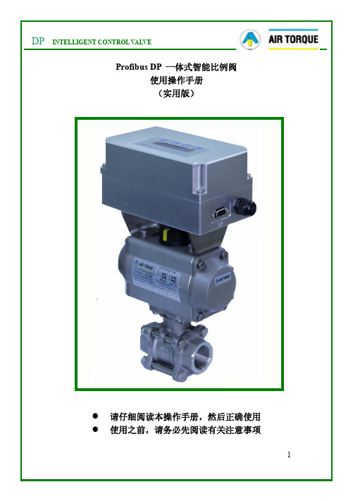
一体式智能比例阀●请仔细阅读本操作手册,然后正确使用●使用之前,请务必先阅读有关注意事项 (3) (3)请仔细地阅读下面的注意事项,并且严格遵守其中的每一条指令。
1word)ID2(高八位))按进入界面继续按继续按直到 Profibus 总线控制,此时再按会增加界面,可以选择PRESS ->FOR 3SC:CONFIG2.Profibus DP LED显示状态PCB主板电源接口:建议将PE口4.Profibus 系统电路连接Sl当定位器在断电或是发生意外情况下,在总线无法控制阀门时,需要定位器的显示元件向左向右键向下键向上键初始化流程说明P=0.0a.若开机显示画面 , 系统进行初始化才能正常工D:NO INIT按切换为0..20mA:若换,出现连接以后按住3S初始化完成,整个初始化过程需要返回界面成功初始化之后增加界面:切换界面。
调节数值,切换界面。
注意:当P=0.0D: INIT OK进入下一级界面后按切换的界面下按恢复默认值,切换为界面后即退回到上级界面。
三、在初始化成功之后进行各项参数设定:后按切换3S进行初始改变设定值方向说明见参数说明中设定方向)OFF,MIN/MAX, MIN/MIN输出的设定。
LCD显示Min/Min AlarmFun调节10-100,。
设置报警的最大位置。
ERR+RAN, RANGE0-100S。
设置错误时间,即达到错误等级所需要的时间。
错误等级的选择,当错误选项被选择,必须在错误时间内达到错误等级设置的误差内,否则,进行错误输出。
选择错误范围。
即输入信号低于/高于范围报警。
RangeError按(详细说明见参数说明中最小位置和最大位置)按值为100。
(详细说明见参数说明中最小位置和最大位置)no/min/max/min&max为阀门排气至最小位置时实现阀门紧闭,67.6 94.9100 1004 5.67.2调节0.1-10.0,默认值5.0。
2-53Catalogue HY11-2500/UKDirectional Control ValveSeries D3W Inductive Position Control2Parker Hannifin GmbH & Co. KG Hydraulic Controls Division Kaarst, GermanyCharacteristics2-54D3W POSITION CONTROL.PMD RHCatalogue HY11-2500/UKDirectional Control ValveSeries D3W Inductive Position Control2Parker Hannifin GmbH & Co. KG Hydraulic Controls Division Kaarst, GermanyOrdering Code3)Only position control code I2 or I54)Only position control code I1 or I42)Only available for styles "E"and "F"2-55Catalogue HY11-2500/UKDirectional Control ValveSeries D3W Inductive Position Control 2Parker Hannifin GmbH & Co. KG Hydraulic Controls Division Kaarst, GermanyOrdering Code2-56D3W POSITION CONTROL.PMD RHCatalogue HY11-2500/UKDirectional Control ValveSeries D3W Inductive Position Control2Parker Hannifin GmbH & Co. KG Hydraulic Controls Division Kaarst, GermanyPosition ControlElectrical characteristics of position control M12x1M12 pin assignment1Normally open 2+ Supply 18...42V 3Normally closed 40V5Earth groundDefinitionsStart position monitored:The valve is de-energized. The inductive switch gives a signal at the moment (below 15% spool stroke) when the spool leaves the spring offset position.End position monitored:The inductive switch gives a signal before ending the stroke (above 85% spool stroke).The switch can only be located opposite the solenoid for direct-controlled valves. This means, if the solenoid is located on the A side of the valve, the switch can only take place on the B side.Protection classIP 65 in accordance with DIN 40050 (plugged and mounted)Ambient temperature [°C]0...+50Supply voltage / ripple[V]18...42 / 10%Current consumption without load[A]≤ 30Max. output current per channel, ohmic [mA]400Min. output load per channel, ohmic [kOhm]100Max. output drop at 0.2A [V]≤ 1.1Max. output drop at 0.4A [V]≤ 1.6EMCEN50081-1 / EN50082-2Max. tolerance ambient field strength [A/m]<1200Min. distance to next AC solenoid [m]>0.1Interface M12x1Wiring min.[mm²] 5 x 0.25 brad shield recommended Wiring length max.[m]50 recommended2-57Catalogue HY11-2500/UKDirectional Control ValveSeries D3W Inductive Position Control2Parker Hannifin GmbH & Co. KG Hydraulic Controls Division Kaarst, GermanyPerformance Curves2-58D3W POSITION CONTROL.PMD RHCatalogue HY11-2500/UKDirectional Control ValveSeries D3W Inductive Position Control2Parker Hannifin GmbH & Co. KG Hydraulic Controls DivisionKaarst, GermanyDimensionsInterface EN 175301-803, DC-solenoid, with plug M12x1*B, E, F -styleAttentionThe switch must be adjusted by the valve manufacturer only. The exchange of individual modules is not permitted.* Delivery includes plug M12 x 1 (see accessories, plug M12x1; order no.: 5004109).The space necessary to remove the plug per EN 175301-803, design type AF is at least 15 mm.The torque for the screw M3 of the plug has to be 0.5 to 0.6 Nm.H, K, M -style。
比例阀使用说明全数字双闭环比例换向阀控制器使用说明书双闭环控制一、概述电路采用32bit高速CPU设计,具有结构简单可靠,参数长时间不会漂移,看门狗设计。
具有模拟量和数字量外部接口设计。
一块控制板可以方便控制比例换向阀,大大简化了常规设计。
二、功能特点1、集成双闭环设计,比例换向阀阀芯位置闭环控制\外部给定反馈闭环控制2、放大器和控制器合二为一,精简设备,减少维护量降低故障率3、具有使用模拟量接口4-20mA(或者0-20mA)反馈、4-20mA(或者0-20mA)(给定与主电路隔离)4、具有数字量接口设计,MODEBUSRS485RTU、CANBUS接口5、可以多个设备进行组网控制,适合多点集中控制6、外部给定反馈闭环控制PID参数调节通过3个电位器调整7、两路阀芯电磁铁控制具有输出过流保护8、看门狗设计,能够及时复位异常工况三、参数1、供电:DC15~30VDC @ 2A2、尺寸123(mm)X160(mm)3、调节精度±1%4、适用范围:华德比例换向阀6通径或10通径带阀芯位置反馈装置进行液压缸、液压缸伸缩位置定位控制,马达行走机构定位控制,液压升降机构定位控制,液压紧紧力装置控制、液压马达行走速度控制等5、工作温度:-30~60摄氏度6、湿度:7、震动:四、典型应用执行机构可以是液压缸,液压马达等执行部件,可以对控制对象进行精准控制五、接线说明六、调整方法此步骤为出厂已经调试好,一般用户无需调整,如果参数确实差异很大,请谨慎操作1、按照接线方法接好线,并认真检查正确后,将控制板上的保险丝去掉,控制板上电后,用万用表的交流档测量COM与L 和COM与R的电压应相同大约在2.3VAC,如果差异大(>0.1VAC)就需要松开位置传感器上的螺丝,将位置传感器的位置通过两个限位螺丝移动,直到测量COM与L 和COM与R的电压应相同为止。
这个步骤一般用户只做检查即可,已经出厂调整过。
成都电气比例阀使用说明
一、安装和保管
1.安装位置:生产现场应尽量避免直接受到热、湿、粉尘、腐蚀性大的气体、液体等
污染,安装位置应符合电气特性及结构尺寸,以免影响使用效果。
2.保管:设备应放置在干燥、清洁、通风良好、无机械震动和有足够空间的仓库里,
防止受潮、受震动,以免影响使用效果。
二、安装
1.参考技术数据:装置的技术数据应按设计要求正确地安装,以确保正确的使用性能;
2.安装方式:安装应严格按照本说明书和设计要求来进行,采用铰接、螺纹式等结构;
3.余量:安装余量应满足设计要求,余量越大,调节精度越高;
4.检验:安装完毕后,进行位置检查,若发现错误应及时更正;
三、调节
1.根据压力变化:当安装完毕后,按照压力变化调节,保证调节精度;
2.灵活调节:阀门的灵活调节大大增强了比例阀的使用效果;
3.使用状态:使用状态应当满足标准要求,只有如此才能保证比例阀的正常使用;
四、操作
1.手动操作:安装完成后,可以采用手动方式对比例阀进行操作,调节比例阀的压力;
2.注意安全:操作阀门过程中,应注意安全,不要将手放入比例阀内;
3.检修维护:操作完成后,应特别注意对比例阀进行检修维护,以确保比例阀的正常
使用。