电子元器件应用-Interfacing the TLV1562 Parallel ADC to the TMS320C54x DSP
- 格式:pdf
- 大小:3.45 MB
- 文档页数:99


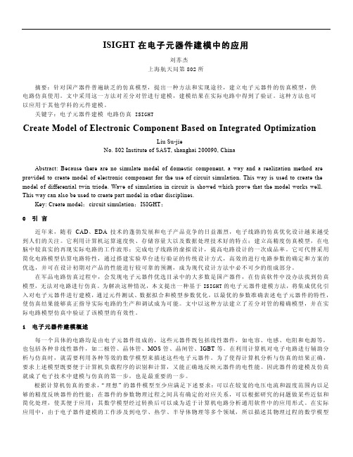
第三章倍频器设计图3_4倍频器模拟实物图3.3倍频器部件设计3.3.1微带到波导过渡微波、毫米波元器件以及子系统最终要应用于整机系统或要连接到测试系统中,这就要求输入、输出接口必须为标准矩形波导。
从标准波导至Ⅱ微带电路要求有良好的过渡,在过渡过程中,不但要完成不同结构的过渡,而且还要实现阻抗变换,使电磁能量损失尽可能的小。
除此之外,还要求装卸容易,重复性、一致性好且易于加工。
波导到微带过渡结构可由多种方式来实现,如微带探针形式I捌,鳍线过渡【矧,小孔耦合I矧,脊波导【25】【圳,本章探索了两种方式。
3.3.1.1脊波导【27】无论哪个标准波导的等效阻抗都比标准微带线特性阻抗50Q要高得多,为了保证两者连接得到较好的匹配,必须在标准波导和微带线之间加变阻器,把波导的等效阻抗逐步降低,这可以用连续过渡或阶梯过渡来实现,前者加工较为复杂(如指数线),且为了满足一定驻波比的要求,过渡段长度也不短,所以一般采用阶梯过渡(即1/4多节变阻器)。
单脊波导就其特点来说,工作频带宽。
另外,当金属脊较高时,电磁能量主要集中于脊下,相当于脊下等效电容增加,等效阻抗当然随之降低,若脊宽与脊高选择合理,机械尺寸上也便于与微带线匹配连接。
当脊高变低,相当于脊下等23电子科技大学硕士学位论文导波波长:铲7丽五‰=冬移啪娆212·66ram以。
^|,m觎29.088nun毛=挠鸵~(3·23)◇一24)其他段作相似计算。
最后得出整个初始脊波导尺寸:S=1.42mm磊=o。
127ram磊=2,5mm畦=o.57ram4--2。
28ram或一1.95mm乞=2。
467mm黧3-6脊渡霉程HFSS串静仿真模型”“”“船器“”8矗即日一茹f鬲●●●‘l_Il,.}li{{lll{~pi£j…t—L}]”J啊||;{,,t{l|}i..j一{-{{l,一,一{:M一\广!}N;再沁_.八l卜Z。
d●__一N?7i{‘;”㈠K’7…Hn{rrV斗÷一—:一3.{÷一曩一丫一{^一{;{{·|l…,{{i}{t|t”…、”…’’…、^‘t一+…””””R_MP””“掰34脊滚霉在HFSS审鹃待囊结采根据设计尺寸在HFSS中仿真并进行优化,得到仿真结聚如图3—7。

光通信关键器件Interleaver的原理和进展
林林
【期刊名称】《东莞理工学院学报》
【年(卷),期】2006(013)003
【摘要】Interleaver(梳状分波器)是DWDM光通信系统中的重要无源器件.对比介绍几种类型Interleaver的原理、结构、性能,并分析它们的发展趋势.
【总页数】4页(P53-56)
【作者】林林
【作者单位】广东医学院,生物医学工程教研室,广东,东莞,523808
【正文语种】中文
【中图分类】TN914
【相关文献】
1.全光通信用关键光电子器件 [J], 何兴仁
2.空间光通信用光收发器件进展及典型应用 [J], 张瑞君
3.全光通信网光电器件及其最新进展(2) [J], 金耀辉;曾庆济;唐晓东;肖石林
4.光通信中关键器件-耦合器 [J], 冯霞;李平;葛祥友
5.日盲紫外光通信系统关键器件 [J], 周志斌;肖沙里;汪科;袁浩;徐志敏
因版权原因,仅展示原文概要,查看原文内容请购买。

元器件知识大全:RFID新一代高级封装技术资料整理者:tughghjghj在当今飞速发展的电子环境中,芯片制造商和封装技术供应商们发现传统的前段制造设备,诸如光刻步进器等,可能会实现成本高效的后段工艺流程(BEOL)器件封装。
尽管高级封装市场的发展空间最初是被PCs行业的蓬勃发展带动起来的,但是现在它们已经不再是主要的增长催化因素。
通信以及手持设备,如手机、PDAs(个人数字助理)、便携式游戏机以及个人通讯系统正在成为新增长阶段的推动因素。
随着数字消费应用的爆炸式发展-性能和波形系统成为必须启用高级封装(AP)技术的必要条件。
在未来五年内,预计通讯芯片组、图形处理器、集成无源元件以及高速PC内存元件将成为AP技术的主要诉求。
随着领先的逻辑芯片制造商们需求量的不断增大,我们共同见证了AP 市场的成长过程。
然而,这一细分市场的另一个转折点可能会来自高速PC内存元件对高级封装技术的诉求。
不管终端设备的推动因素如何强劲,仅高性能封装技术的需求不断升级,就带动了金凸块技术和锡铅凸块技术的需求增长,同时获得增长的还包括晶圆级封装技术和后护层技术。
本文将分析当前的以及正在不断涌现的AP应用,其中光蚀刻设备以其突出的优势将获得部署良机。
主要的AP光刻市场光刻技术是影响晶圆植球品质的最重要因素之一。
如图1所示,推动AP市场发展的因素是多元化的。
举例说明,液晶显示器(LCDs)是一款产量非常高的成熟产品,也是金凸块技术的主要供应市场。
新的晶圆级封装(WLP)技术将即将渗透到微处理器和射频(RF)器件市场。
同时我们也期待PPL技术能够在高级器件封装领域获得增长金凸块技术金凸块技术主要用于液晶显示器(LCD)面板上驱动ICs的封装。
尽管日本已经成为业界领先的LCD面板和驱动ICs制造国,然而,出于成本和供应链等环节的考量,显示器制造还是在向其它地区的商业制造厂平稳过渡-台湾、韩国以及中国,其中向中国的制造厂过渡正在逐步攀升。
IMPORTANT NOTICETexas Instruments Incorporated and its subsidiaries (TI) reserve the right to make corrections, modifications, enhancements, improvements, and other changes to its products and services at any time and to discontinue any product or service without notice. Customers should obtain the latest relevant information before placing orders and should verify that such information is current and complete. All products are sold subject to TI’s terms and conditions of sale supplied at the time of order acknowledgment.TI warrants performance of its hardware products to the specifications applicable at the time of sale in accordance with TI’s standard warranty. Testing and other quality control techniques are used to the extent TI deems necessary to support this warranty. Except where mandated by government requirements, testing of all parameters of each product is not necessarily performed.TI assumes no liability for applications assistance or customer product design. Customers are responsible for their products and applications using TI components. To minimize the risks associated with customer products and applications, customers should provide adequate design and operating safeguards.TI does not warrant or represent that any license, either express or implied, is granted under any TI patent right, copyright, mask work right, or other TI intellectual property right relating to any combination, machine, or process in which TI products or services are used. Information published by TI regarding third-party products or services does not constitute a license from TI to use such products or services or a warranty or endorsement thereof. Use of such information may require a license from a third party under the patents or other intellectual property of the third party, or a license from TI under the patents or other intellectual property of TI.Reproduction of information in TI data books or data sheets is permissible only if reproduction is without alteration and is accompanied by all associated warranties, conditions, limitations, and notices. Reproduction of this information with alteration is an unfair and deceptive business practice. TI is not responsible or liable for such altered documentation.Resale of TI products or services with statements different from or beyond the parameters stated by TI for that product or service voids all express and any implied warranties for the associated TI product or service and is an unfair and deceptive business practice. TI is not responsible or liable for any such statements. Following are URLs where you can obtain information on other Texas Instruments products and application solutions:Products ApplicationsAmplifiers Audio /audioData Converters Automotive /automotiveDSP Broadband /broadbandInterface Digital Control /digitalcontrolLogic Military /militaryPower Mgmt Optical Networking /opticalnetwork Microcontrollers Security /securityTelephony /telephonyVideo & Imaging /videoWireless /wirelessMailing Address:Texas InstrumentsPost Office Box 655303 Dallas, Texas 75265Copyright 2003, Texas Instruments Incorporated。
高端电子元件市场现状据统计,目前世界电子元件的市场规模大约每年1600亿美元左右,估计到2022年,市场规模将突破2000亿美元。
电子元件几个较大的应用领域包括工业电子产品、计算机、消费类电子以及通信。
在各类整机电路中,无源元件和有源器件的数量比例通常在20:1至50:1左右,其中一些高端电子产品,如移动手机、笔记本电脑等当中,无源元件的比例更高,有时可达到100:1。
无源元件的成本平均占整机中元器件总成本的1/3左右。
随着电子产品功能的进一步提高,整机对元器件数量的需求也逐步增加。
随着集成电路(微处理器)集成度的提高,其周边的无源元件的需要量也逐步上升。
随着世界电子制造业向中国大规模转移,我国的电子元件市场以近年来每年都20%的增长率增长。
粗略测算目前我国电子元件市场容量约在350亿美元左右,在不久的将来,我国可望成为全球最大的电子元件消费市场。
一些重要的高端电子元件的国际市场状况如下:多层陶瓷电容器(MLCC)多层陶瓷电容器目前国际上用量最大、进展最快的片式元件之一。
MLCC主要应用于各类军用、民用整机的震荡、耦合、滤波、旁路电路中,应用领域已经拓展到自动掌握仪表、计算机、手机、数字家电、汽车电等行业。
目前,多层陶瓷电容器已构成了电容器市场的主体,在大容量市场(10μF以下)中,陶瓷电容器已部分取代钽电容器,而在1μF以下,陶瓷电容器占肯定优势。
全球市场的需求量从1998年的3070亿只,增至2022年11000亿只。
年增长速度近20%。
市场需求巨大,产业化市场前景特别宽阔。
片式电感类元件多层片式电感类元件包括了一大类具有叠层式介质/线圈结构的新型电子元件,是电感类元件进展的方向,也是三大类无源片式元件中技术含量最高的一大类。
目前,这类元件已形成了规模相当大的产业和近百亿美元的国际市场。
片式电感器的主要应用领域包括移动通信、计算机、音像产品、家电、办公自动化等。
估计在今后若干年中,随着第三代移动通信技术、数字电视、高速计算机、蓝牙产品等新一代数字化电子产品的推出和世界各国EMI掌握标准的相继制订,对各种片式电感类元件,特殊是抗EMI类片式电感元件的需求将急剧上升。
光电子器件的创新与应用随着科学技术的不断发展,光电子技术作为新兴的技术领域,已经逐渐成为了人类社会中的不可或缺的一部分。
在这一领域中,光电子器件作为其中的核心组成部分,扮演着不可替代的角色。
光电子器件的创新性发展和应用,也成为了科学技术领域中最具有前瞻性和发展空间的一项工作。
一、光电子器件的基本概念光电子器件是指在光电子技术的基础上,能够将光信号转换为电信号,或者将电信号转换为光信号,并以此完成信息传输、显示、存储等多种功能的电子器件。
光电子器件的种类繁多,涉及到光电探测器、光纤通信、激光器、LED发光二极管等多个领域,并在医疗、通讯、生产等领域中得到广泛应用。
二、光电子器件的创新光电子器件的创新涉及到技术和工艺两个方面。
其中技术方面主要表现在光电探测、光电转换、光调制等技术的发展上,而工艺方面则包括晶体生长、微加工、组装等方向的研究。
1.技术创新技术创新是光电子器件创新的重要方向。
针对传统器件在性能、可靠性、应用领域等方面存在的局限性,科研人员借助新材料、新工艺和新理念,逐渐推动了光电子器件的技术进步。
例如,在光电探测器的研究中,利用单层碳纳米管、人工合成纳米结构、金属半导体纳米结构等新材料或结构进行设计开发,将探测器的灵敏度、响应速度、性能稳定性等方面都得到极大的提升。
在光调制器领域,研究人员结合现代微电子技术,成功地实现了光子晶体光调制器、电吸收光调制器、混合集成光调制器等多种功能完备、性能优越的光调制器。
2.工艺创新工艺创新是光电子器件创新的另一个重要方向。
随着科技的不断发展,光电子器件制备工艺也在不断发展。
比如在光纤通信技术中,通过改变光纤的材料合成工艺、诸如拉锥、折弯等工艺操作研究,成功地实现了高品质光纤的制备。
在半导体激光器领域中,采用更多的微电子技术,包括刻蚀、离子注入、多量子阱生长等技术,提高了半导体激光器的制造效率、器件质量、可靠性和成品率。
三、光电子器件的应用光电子器件的广泛应用,从某种意义上来说,既体现了光电子器件创新成果的重要性,又为科学技术的发展带来了众多机遇。
FEATURES APPLICATIONSDESCRIPTIONRI-I15-112B-02SCBS825–JULY2004–REVISED DECEMBER2005Tag-it™HF-I PLUS TRANSPONDER INLAYSMEDIUM RECTANGLE•Product Authentication•ISO/IEC15693-2,-3;ISO/IEC18000-3Compliant•Library•Supply-Chain Management•13.56-MHz Operating Frequency•Asset Management•2048-Bit User Memory in64-Bit×32-Bit•Ticketing/Stored ValueBlocks•User and Factory Lock Per Block•Application Family Identifier(AFI)•Data Storage Format Identifier(DSFID)•Combined Inventory Read BlockTexas Instruments Tag-it™HF-I plus transponder inlays consist of13.56-MHz high-frequency(HF)transponders that are compliant with the ISO/IEC15693and ISO/IEC18000-3global open standards.These products offer a user-accessible memory of2048bits,organized in64blocks,and an extensive command set available in six different antenna shapes,with frequency offset for integration into paper,PVC,or other substrates.The Tag-it HF-I plus transponder inlays are manufactured with TI’s patented laser tuning process to provide consistent read performance.Prior to delivery,the transponders undergo complete functional and parametric testing,in order to provide the high quality that customers have come to expect from TI.The Tag-it HF-I plus transponder inlays are well suited for a variety of applications including,but not limited to, product authentication,library,supply-chain management,asset management,and ticketing/stored value applications.Please be aware that an important notice concerning availability,standard warranty,and use in critical applications of TexasInstruments semiconductor products and disclaimers thereto appears at the end of this data sheet.Tag-it is a trademark of Texas Instruments.PRODUCTION DATA information is current as of publication date.Copyright©2004–2005,Texas Instruments Incorporated Products conform to specifications per the terms of the TexasInstruments standard warranty.Production processing does notnecessarily include testing of all parameters.RI-I15-112B-02SCBS825–JULY 2004–REVISED DECEMBER 2005SPECIFICATIONS (1)PART NUMBER RI-I15-112B-02Supported standardISO/IEC 15693-2,-3;ISO/IEC 18000-3Recommended operating frequency 13.56MHz14.1MHz ±200kHz (includes frequency offset to compensate PVC Passive resonance frequency (at 25°C)lamination)Typical required activation field strength to read (at 25°C)98dB µA/m (2)Typical required activation field strength to write (at 25°C)101dB µA/m (2)Factory programmed read-only number 64bitsMemory (user programmable)2k bits organized in 64-bit ×32-bit blocks Typical programming cycles (at 25°C)100,000Data retention time (at 55°C)>10yearsSimultaneous identification of tags Up to 50tags per second (reader/antenna dependent)Antenna size 34mm ×65mm (~1.34in ×~2.56in)Foil width 48mm ±0.5mm (1.89in ±0.02in)Foil pitch 101.6mm +0.1mm/–0.4mm (4in)Chip area:0.355mm (~0.014in)Thickness Antenna area:0.085mm (~0.0033in)Base materialSubstrate:PET (polyethylenetherephtalate);Antenna:aluminum Smallest bending radius allowed 18mm (~0.71in)Operating temperature–25°C to 70°CStorage temperature (single inlay)–40°C to 85°C (warpage may occur at upper temperature range)Storage temperature (on reel)–40°C to 40°CSingle-row tape wound on cardboard reel with 500-mm diameter Reel outer width:approximately 60mm (~2.36in)DeliveryReel inner width:approximately 50mm (~1.97in)Hub diameter:76.2mm (3in)Typical quantity of good units per reel 5,000(1)For highest possible read-out coverage,operate readers at a modulation depth of 20%or higher.(2)After integration into paperSUPPORTED COMMAND SETREQUEST MODE (1)REQUESTREQUEST CODEINVENTORYADDRESSEDNON-ADDRESSEDSELECTAFI ISO 15693Mandatory and Optional Commands Inventory 0x01ü–––üStay Quiet0x02–ü–––Read_Single_Block 0x20üüüüüWrite_Single_Block 0x21–üüü–Lock_Block 0x22–üüü–Read_Multi_Blocks 0x23üüüüüWrite_Multi_Blocks 0x24–––––Select Tag 0x25–ü–––Reset to Ready 0x26–üüü–Write_AFI 0x27–üüü–Lock_AFI 0x28–üüü–Write DSFID0x29–üüü–(1)ü=Implemented,–=Not applicable2Submit Documentation FeedbackBlock #1236263RI-I15-112B-02SCBS825–JULY 2004–REVISED DECEMBER 2005SUPPORTED COMMAND SET (continued)REQUEST MODE (1)REQUESTREQUEST CODEINVENTORYADDRESSEDNON-ADDRESSEDSELECTAFI ISO 15693Mandatory and Optional Commands Lock DSFID 0x2A –üüü–Get_System_info 0x2B üüüüüGet_M_BLK_Sec_St 0x2C üüüüüTI Custom Commands Write_2_Blocks 0xA2–üüü–Lock_2_Blocks0xA3–üüü–MEMORY ORGANIZATION3Submit Documentation FeedbackPACKAGING INFORMATIONOrderable Device Status (1)Package Type Package Drawing Pins Package Qty Eco Plan (2)Lead/Ball FinishMSL Peak Temp (3)RI-I15-112B-02OBSOLETERFIDNTFGTBDCall TICall TI(1)The marketing status values are defined as follows:ACTIVE:Product device recommended for new designs.LIFEBUY:TI has announced that the device will be discontinued,and a lifetime-buy period is in effect.NRND:Not recommended for new designs.Device is in production to support existing customers,but TI does not recommend using this part in a new design.PREVIEW:Device has been announced but is not in production.Samples may or may not be available.OBSOLETE:TI has discontinued the production of the device.(2)Eco Plan -The planned eco-friendly classification:Pb-Free (RoHS),Pb-Free (RoHS Exempt),or Green (RoHS &no Sb/Br)-please check /productcontent for the latest availability information and additional product content details.TBD:The Pb-Free/Green conversion plan has not been defined.Pb-Free (RoHS):TI's terms "Lead-Free"or "Pb-Free"mean semiconductor products that are compatible with the current RoHS requirements for all 6substances,including the requirement that lead not exceed 0.1%by weight in homogeneous materials.Where designed to be soldered at high temperatures,TI Pb-Free products are suitable for use in specified lead-free processes.Pb-Free (RoHS Exempt):This component has a RoHS exemption for either 1)lead-based flip-chip solder bumps used between the die and package,or 2)lead-based die adhesive used between the die and leadframe.The component is otherwise considered Pb-Free (RoHS compatible)as defined above.Green (RoHS &no Sb/Br):TI defines "Green"to mean Pb-Free (RoHS compatible),and free of Bromine (Br)and Antimony (Sb)based flame retardants (Br or Sb do not exceed 0.1%by weight in homogeneous material)(3)MSL,Peak Temp.--The Moisture Sensitivity Level rating according to the JEDEC industry standard classifications,and peak solder temperature.Important Information and Disclaimer:The information provided on this page represents TI's knowledge and belief as of the date that it is provided.TI bases its knowledge and belief on information provided by third parties,and makes no representation or warranty as to the accuracy of such information.Efforts are underway to better integrate information from third parties.TI has taken and continues to take reasonable steps to provide representative and accurate information but may not have conducted destructive testing or chemical analysis on incoming materials and chemicals.TI and TI suppliers consider certain information to be proprietary,and thus CAS numbersand other limited information may not be available for release.In no event shall TI's liability arising out of such information exceed the total purchase price of the TI part(s)at issue in this document sold by TI to Customer on an annual basis.PACKAGE OPTION ADDENDUM2-Nov-2009Addendum-Page 1IMPORTANT NOTICETexas Instruments Incorporated and its subsidiaries(TI)reserve the right to make corrections,modifications,enhancements,improvements, and other changes to its products and services at any time and to discontinue any product or service without notice.Customers should obtain the latest relevant information before placing orders and should verify that such information is current and complete.All products are sold subject to TI’s terms and conditions of sale supplied at the time of order acknowledgment.TI warrants performance of its hardware products to the specifications applicable at the time of sale in accordance with TI’s standard warranty.Testing and other quality control techniques are used to the extent TI deems necessary to support this warranty.Except where mandated by government requirements,testing of all parameters of each product is not necessarily performed.TI assumes no liability for applications assistance or customer product design.Customers are responsible for their products and applications using TI components.To minimize the risks associated with customer products and applications,customers should provide adequate design and operating safeguards.TI does not warrant or represent that any license,either express or implied,is granted under any TI patent right,copyright,mask work right, or other TI intellectual property right relating to any combination,machine,or process in which TI products or services are rmation published by TI regarding third-party products or services does not constitute a license from TI to use such products or services or a warranty or endorsement e of such information may require a license from a third party under the patents or other intellectual property of the third party,or a license from TI under the patents or other intellectual property of TI.Reproduction of TI information in TI data books or data sheets is permissible only if reproduction is without alteration and is accompanied by all associated warranties,conditions,limitations,and notices.Reproduction of this information with alteration is an unfair and deceptive business practice.TI is not responsible or liable for such altered rmation of third parties may be subject to additional restrictions.Resale of TI products or services with statements different from or beyond the parameters stated by TI for that product or service voids all express and any implied warranties for the associated TI product or service and is an unfair and deceptive business practice.TI is not responsible or liable for any such statements.TI products are not authorized for use in safety-critical applications(such as life support)where a failure of the TI product would reasonably be expected to cause severe personal injury or death,unless officers of the parties have executed an agreement specifically governing such use.Buyers represent that they have all necessary expertise in the safety and regulatory ramifications of their applications,and acknowledge and agree that they are solely responsible for all legal,regulatory and safety-related requirements concerning their products and any use of TI products in such safety-critical applications,notwithstanding any applications-related information or support that may be provided by TI.Further,Buyers must fully indemnify TI and its representatives against any damages arising out of the use of TI products in such safety-critical applications.TI products are neither designed nor intended for use in military/aerospace applications or environments unless the TI products are specifically designated by TI as military-grade or"enhanced plastic."Only products designated by TI as military-grade meet military specifications.Buyers acknowledge and agree that any such use of TI products which TI has not designated as military-grade is solely at the Buyer's risk,and that they are solely responsible for compliance with all legal and regulatory requirements in connection with such use. TI products are neither designed nor intended for use in automotive applications or environments unless the specific TI products are designated by TI as compliant with ISO/TS16949requirements.Buyers acknowledge and agree that,if they use any non-designated products in automotive applications,TI will not be responsible for any failure to meet such requirements.Following are URLs where you can obtain information on other Texas Instruments products and application solutions:Products ApplicationsAmplifiers AudioData Converters AutomotiveDLP®Products BroadbandDSP Digital ControlClocks and Timers MedicalInterface MilitaryLogic Optical NetworkingPower Mgmt SecurityMicrocontrollers TelephonyRFID Video&ImagingRF/IF and ZigBee®Solutions WirelessMailing Address:Texas Instruments,Post Office Box655303,Dallas,Texas75265Copyright©2009,Texas Instruments Incorporated。