电子元器件应用-Agilent E4980A精密LCR表20Hz至2MHz--阻抗测量的新标准
- 格式:pdf
- 大小:375.87 KB
- 文档页数:2

海底石油管道金属探测器设计及应用分析发布时间:2022-07-07T01:23:12.704Z 来源:《科学与技术》2022年3月第5期作者:苏方波谢培刘帅[导读] 我国海洋资源较为丰富苏方波谢培刘帅杭州丰禾石油科技有限公司摘要:我国海洋资源较为丰富,再过去受限于技术条件,无法对海洋资源进行有效利用,而目前社会发展突飞猛进,带动着各项技术的更新,使海洋资源开发具备了可能性。
海底石油管道承担着石油的输送任务,但海底工作环境恶劣,为避免发生被海水侵蚀发生泄漏问题,做好海底石油管道的侵蚀检测是关键。
关键词:海底石油管道;金属探测器;前言:现如今日均消耗的能源数量巨大,而新能源所产生的能源有限,无法满足现时的需求,在能源使用面临困境,还要保护生态环境不能过度开采的情况下,海洋资源成为了能源供应的另一出路,各项石油开采技术的发展,海底石油开采量越来越丰富,而长时间的开采作业带来了新的问题,海水对石油输送管道有较高的侵蚀性,而石油管道作为运输的主要设施,影响着海底石油开采、运输及生态保护。
1.海底石油管道的重要性海底石油管道终日浸泡在海水中,工作环境恶劣,盐度、洋流及开采施工作业都会对管道产生影响,以便使得管道极易出现问题,因管道断裂、遭腐蚀泄露的案例并不少见,石油能源大量被浪费,经济遭受打击,同时泄露区域及周边环境被污染。
海底石油管道发生泄漏,比陆地管道泄露造成的危害要大很多,并且难以处理,因此海底管道检测对于排除管道安全隐患,确保管道安全有极大的意义。
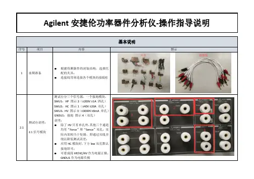
2.金属探测器的设计金属探测器的设计与常规的线圈设计结构相同,在电路设计与功能上略有不同。
发射极有两个部分,即振荡器与发射线圈,接收极由接收线圈、相位检测电路与PIC微处理器构成。
PIC微处理器连接LCD显示器。
发射频率在55KHz上,接收线圈与发射极存在于同个铜芯线圈上。
发射极在外端,而接收极与振幅相位检测装置由一系列简单的无源滤波器、放大器、逻辑门构成。

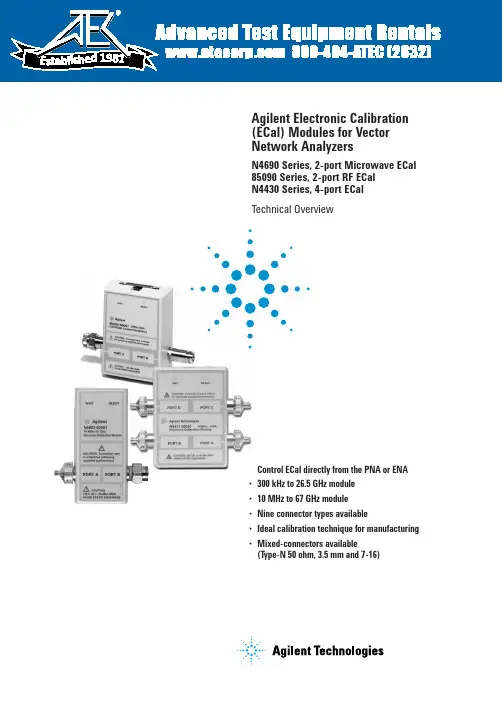
•Control ECal directly from the PNA or ENA •300 kHz to 26.5 GHz module •10 MHz to 67 GHz module •Nine connector types available•Ideal calibration technique for manufacturing •Mixed-connectors available(Type-N 50 ohm, 3.5 mm and 7-16)Agilent Electronic Calibration (ECal) Modules for Vector Network AnalyzersN4690 Series, 2-port Microwave ECal 85090 Series, 2-port RF ECal N4430 Series, 4-port ECalTechnical Overview198125. ENA series consists of E5070/1.6. ENA-L series consists of E5061/2.7.N3381/2/3 have been discontinued.8. PNA-L series consists of N5230.ECal and Agilent Network Analyzer ConfigurationsPNA and ENA SeriesECal modules are controlled directly from the PNA and ENA Series network analyzers. No external PC is required. Simply connect the ECal module to the USB port on the network analyz-er. You can control your calibra-tion from the front panel keys of the PNA Series or automatically by your user program.Calibration configuration using the PNA series3Perform adapter removal calibrations fasterSome analyzers, such as later versions of the 8753 and 8720, offer adapter removal calibration for non-insertable and mixed connector measurement capabil-ity. Since this method requires two full two-port calibrations, it is often time consuming and prone to operator errors. Using ECal to perform the two-port calibrations addresses both of these concerns by reducing the calibration time and the number of connections, simplifying the overall adapter removal process.Perform a User-characterization Normally, when you perform a calibration with an ECal module, the error terms for a calibration are computed using the factory characterization (data) stored in the module. User-characteriza-tion allows you to change the characterization of the module in two ways:• Change the connector configuration: allows you to add an adapter or fixture to the test port of the module and embed the effects into the characterization of the module. The result of the new characterization extends the reference plane from one or more of the module’s test ports to those on the adapter (or fixture).• Modify the state settings: allows you to specify the number of data points (1601 maximum) or other stimulus settings the module uses to perform a cali-bration.When you perform a user-charac-terization, the factory characteri-zation data remains stored in the module’s memory. At calibration, you can select the factory characterization or any of the user-defined characterizations stored in the module. The module can store up to five user-defined characterizations (in addition to the factory characterization data). User-characterization is available with PNA and ENA Series Network Analyzers.41. If the maximum input power is exceeded when calibrating, compression may occur.2. When using the PNA-X, the power level can be increased after calibration with minimal impact on measurement accuracy.3. When mated with male connectors with a 0.77 mm (0.030 in) to 0.86 mm (0.034 in) pin diameter51. When applied power exceeds +9 dBm, calibration results will be degraded from the performance indicated in the table.2. When applied power exceeds –5 dBm, calibration results will be degraded from the performance indicated in the table.3. 3.5 mm modules have precision slotless connectors that guarantee the best calibration accuracy is transferred to your system.61.When applied power exceeds +9 dBm, calibration results will be degraded from the performance indicated in the table.2. When applied power exceeds –5 dBm, calibration results will be degraded from the performance indicated in the table.73. Performance from 9 kHz to 300 kHz is valid only for the E5071C ENA network analyzer with firmware version A.09.10 or higher.4. 9 to 13.5 GHz range not vaild for the N4431A81. When applied power exceeds –7 dBm, calibration results will be degraded from the performance indicated in this table.2. Values based on using the PNA Network Analyzer N5230A Option 240 or 245910Ordering informationSelect an ECal module based on the connector type required and the frequency range of your vector network analyzer (refer to table below).OptionsOption Description00F Replace f-m connectors on ECal module(s) with f-f connectors 00M Replace f-m connectors on ECal module(s) with m-m connectors00A Adds male-to-male and female-to-female adapters (also adds a 5/16” 90 N-cm (8 in-lb) torque wrench to 3.5 mm modules)1A7ISO 17025 compliant calibration A6J ANSI Z540 compliant calibrationUK6Commercial calibration certificate with measured data M0F f-m connectors on ECal module(s)010Four female, 3.5 mm connectors 020Four female, Type-N 50 ohm connectorsECal modules and available options2-portConnector Frequency range ECal module Available options Type model number Type-F300 kHz to 3 GHz85099C 00A, 00F, 00M, UK6, M0FType-N 300 kHz to 9 GHz 85092C00A, 00F, 00M, UK6, 1A7, A6J, M0F,50 ohms mixed-connectorsType-N 300 kHz to 18 GHz N4690B00A, 00F, 00M, UK6, 1A7, A6J, M0F 50 ohmsType-N 300 kHz to 3 GHz 85096C 00A, 00F, 00M, UK6, M0F75 ohms3.5 mm 300 kHz to 9 GHz85093C00A, 00F, 00M, UK6, 1A7, A6J, M0F mixed connectors3.5 mm 300 kHz to 26.5 GHz N4691B 00A, 00F, 00M, UK6, 1A7, A6J, M0F 7 mm 300 kHz to 9 GHz 85091C UK6, 1A7, A6J 7 mm 300 kHz to 18 GHz N4696BUK6, 1A7, A6J7-16 300 kHz to 7.5 GHz 85098C 00A, 00F, 00M, UK6, M0F, mixed-connectors 2.92 mm 10 MHz to 40 GHz N4692A 00A,00F, 00M, UK6, 1A7, A6J, M0F 2.4 mm 10 MHz to 50 GHz N4693A 00A,00F, 00M, UK6, 1A7, A6J, M0F 1.85 mm10 MHz to 67 GHzN4694A00A,00F, 00M, UK6, 1A7, A6J, M0F4-portConnector Frequency range ECal module Available options Type model number 3.5 mm or 9 kHz to 13.5 GHz N4431B010, 020, UK6, 1A7, A6J, mixed-connectorsType-N 50 ohms Type-N 300 kHz to 18 GHz N4432A 020, mixed-connectors 50 ohms 3.5 mm300 kHz to 20 GHzN4433A010Notes:1. Order the 85097B interface module if you will be using ECal with your 8719, 8720, 8722 or 8753. (Please reference the ECal and network analyzer/firmware compatibility table on page 3.) The 85097B con-sists of an interface module and a power supply.2.When using the N469x ECal prod-ucts with the 8720 or 8753 network analyzer families, an adapter cable (8121-1047) is needed. This adapter cable is orderable as an option with the 85097B.1.Performance from 9 kHz to 300 KHz is valid only for the E5071C ENA network analyzer with firmware version A.09.10 or higher.1111.Limits ECal module high frequency to 7.5 GHz.Remove all doubtOur repair and calibration services will get your equipment back to you, performing like new, when prom-ised. You will get full value out of your Agilent equipment through-out its lifetime. Your equipment will be serviced by Agilent-trained technicians using the latest factory calibration procedures, automated repair diagnostics and genuine parts. You will always have the utmost confidence in your measurements. For information regarding self maintenance of this product, please contact your Agilent office.Agilent offers a wide range of ad-ditional expert test and measure-ment services for your equipment, including initial start-up assistance, onsite education and training, as well as design, system integration, and project management.For more information on repair and calibration services, go to:/find/removealldoubt/find/emailupdatesGet the latest information on theproducts and applications you select./find/agilentdirectQuickly choose and use your testequipment solutions with confidence./find/openAgilent Open simplifies the process of connecting and programming test systems to help engineers design, validate and manufacture electronic products. Agilent offers open connectivity for a broad range of system-ready instruments, open industry software, PC-standard I/O and global support, which are combined to more easily integrate test system development.For more information on Agilent Technol-ogies’ products, applications or services, please contact your local Agilent office. The complete list is available at:/find/contactus Americas Canada(877) 894-4414Latin America 305 269 7500United States (800) 829-4444Asia Pacific Australia 1 800 629 485China800 810 0189Hong Kong 800 938 693India 1 800 112 929Japan 0120 (421) 345Korea 080 769 0800Malaysia 1 800 888 848Singapore 180****8100Taiwan 0800 047 866Thailand1 800 226 008Europe & Middle East Austria 01 36027 71571Belgium 32 (0) 2 404 93 40 Denmark 45 70 13 15 15Finland 358 (0) 10 855 2100France 0825 010 700**0.125 €/minuteGermany ************Ireland 1890 924 204Israel 972-3-9288-504/544Italy 39 02 92 60 8484Netherlands 31 (0) 20 547 2111Spain 34 (91) 631 3300Sweden 0200-88 22 55Switzerland 0800 80 53 53United Kingdom 44 (0) 118 9276201Other European Countries:/find/contactusRevised: October 6, 2008© Agilent Technologies, Inc. 2002-2009Printed in USA, February 3, 20095963-3743EWindows ®and Windows NT ®are U.S. registered trademarks of Microsoft Corp.Product specifications and descriptions in this document subject to change without notice.Web ResourcesVisit our Web sites, for additional product information and literature.Electronic calibration (ECal):/find/ecalPNASeries network analyzers:/find/pnaTest and measurement accessories:/find/accessories。

Product Declassification and SecurityProduct Name: Precision LCR MeterModel Number(s): E4980APage 1 of 7E4980A Security FeaturesRev. 1.0E4980-90802 March 2006Copyright 2006 Agilent Technologies1981Contacting Agilent Sales and Service OfficesAssistance with test and measurements needs and information on finding a local Agilent office is available on the internet at, /find/assist. If you do not have access to the internet, please contact your field engineer.Note: In any correspondence or telephone conversation, refer to the signal source analyzer by its model number and full serial number. With this information, the Agilent representative can determine whether your unit is still within its warranty period.Product Declassification and SecurityModel Number(s): E4980AProduct Name: Precision LCR MeterThis document describes instrument security features and the steps to declassify an instrument through memory sanitization or removal. For additional information please go to/find/ad and click on the security instrument tab.Table of ContentsTerms and Definitions (3)Instrument Memory (4)Memory Clearing, Sanitization and/or Removal (5)User and Remote Interface Security (6)Procedure for Declassifying a Faulty Instrument (7)Page 2 of 7Terms and DefinitionsDefinitions:Clearing – Clearing is the process of eradicating the data on media before reusing the media so that the data can no longer be retrieved using the standard interfaces on the instrument. Clearing is typically used when the instrument is to remain in an environment with an acceptable level of protection.Sanitization – Sanitization is the process of removing or eradicating stored data so that the data cannot be recovered using any known technology. Instrument sanitization is typically required when an instrument is moved from a secure to a non-secure environment such as when it is returned to the factory for calibration. (The instrument is declassified) Agilent memory sanitization procedures are designed for customers who need to meet the requirements specified by the US Defense Security Service (DSS). These requirements are outlined in the “Clearing and Sanitization Matrix” issued by the Cognizant Security Agency (CSA) and referenced in National Industrial Security Program Operating Manual (NISPOM) DoD 5220.22M ISL 01L-1 section 8-301.Security Erase – Refers to either the clearing or sanitization features of Agilent instruments.Instrument declassification – A term that refers to procedures that must be undertaken before an instrument can be removed from a secure environment such as is the case when the instrument is returned for calibration. Declassification procedures will include memory sanitization and or memory removal. Agilent declassification procedures are designed to meet the requirements specified by the DSS NISPOM security document (DoD 5220.22M chapter 8)Page 3 of 7Page 4 of 7Instrument MemoryThis section contains information on the types of memory available in your instrument. It explains the size of memory, how it is used, its location, volatility, and the sanitization procedure.Summary of instrument memory - base instrumentMemory Type and SizeW r i t a b l e D u r i n g N o r m a l O p e r a t i o nD a t a R e t a i n e d W h e n P o w e r e d O f fPurpose/ContentsData Input MethodLocation in Instrument and RemarksSanitization ProcedureMain Memory (FLASH) 8 MB No No Firmware operating memory Operatingsystem (notuser) PPMC CPU Board NAMemory (EEPROM) 1 KB Yes Yes GPIB SettingLAN Setting UserModifiable PPMC CPU Board Reset to Factory Setting Memory (FLASH) 8 MBYes Yes Save/Recall Files,User Correction Data,Beeper Tone/State, Handler/Scanner State,Data/Image Dump file name numberUserModifiablePPMC CPU BoardReset to Factory SettingNo Yes Serial Number,Installed Option Factory or Service OnlyA1 Mother BoardNot Required.Nomeasurement data present Memory (EEPROM) 256 KBYesYesNumber of Power On times Non-User ModifiableA1 Mother Board NoneMemory (EEPROM) 32 KB No Yes System Calibration Data Factory orServiceOnly A2 Analog BoardNot Required.Nomeasurement data presentMemory (MPU) 128 B Yes Yes Power onAccumulate TimeNon-User ModifiableDisplay Interface Board NoneMemory Clearing, Sanitization and/or Removal ProceduresThis section explains how to clear, sanitize, and remove memory from you instrument for all memory that can be written to during normal operation and for which the clearing and sanitization procedure is more than trivial such as rebooting your instrument.PPMC CPU Board Main Memory (FLASH)Description andpurposeFirmware for instrument operationSize 8 MBMemory clearing Cycle PowerMemory sanitization Cycle PowerMemory removal This memory can not be removed without damaging the instrument.Write protecting N/APPMC CPU Board (EEPROM)Description andpurposeStores GPIB and LAN addresses setting.Size 1KBMemory clearing Press [Preset] > FACTORY DEFAULT > OK.Memory sanitization Press [Preset] > FACTORY DEFAULT > OK.Memory removal This memory can not be removed without damaging the instrument.Write protecting N/APPMC CPU Board (FLASH)Description and purpose Stores the Save/Recall Files, User Correction Data, Beeper Tone/State, Handler/Scanner State, and Data/Image Dump file name number.Size 8MBMemory clearing Press [Preset] > FACTORY DEFAULT > OK.Memory sanitization This memory can not be sanitized.Memory removal This memory can not be removed without damaging the instrument.Write protecting N/AA1 Mother BoardDescription andpurposeStores the Serial Number, Installed Option, and Number of Power On times. Size 256 KBMemory clearing They can not be cleared at customer site.Memory sanitization They can not be sanitized at customer site.Memory removal This memory can not be removed without damaging the instrument.Write protecting N/AA2 Analog BoardDescription andpurposeStores the system calibration data which is stored by factory or service center. Size 256 KBMemory clearing Adjustment clears the data. The adjustment must be performed Agilent’squalified service personnel.Memory sanitization Adjustment sanitizes the data. The adjustment must be performed Agilent’squalified service personnel.Memory removal This memory can not be removed without damaging the instrument.Write protecting N/APage 5 of 7Display Interface BoardPower On Accumulate times.Description andpurposeSize 128BMemory clearing They can not be cleared at customer site.Memory sanitization They can not be sanitized at customer site.Memory removal This memory can not be removed without damaging the instrument.Write protecting N/AUser and Remote Interface Security MeasuresScreen and Annotation BlankingThe display blanking feature is available.The operator can perform the following keystrokes to activate the display blank.[Display Format] > DISPLAY BLANKOr can activate the display blank by the following SCPI command.:DISPlay:ENABle {ON|OFF}USB Mass Storage Device SecurityE4980A does not have a capability to disable a USB Mass Storage Device.Remote Access InterfacesThe user is responsible for providing security for the I/O ports for remote access by controlling physical access to the I/O ports. The I/O ports must be controlled because they provide access to all user settings, user states and the display image.The I/O ports include USB, GPIB and LAN.The LAN port provides the following services.z httpz socketsz telnetz VXI-11There is also a ‘ping’ service, which presently cannot be selectively disabled. The concern here might be that it is possible to discover IP addresses of connected instruments in order to query their setups over the net or break into the code.Page 6 of 7Procedure for Declassifying a Faulty InstrumentIf the instrument is not functioning and you are unable to clear/sanitize the stored user information, you must physically remove the PPMC CPU and display boards from the instrument. See to the Service Guide for removal procedures.Page 7 of 7。

文件名称 Agilent E4981A 容量测试仪操作使用规程文件编号 JEYSDCJLT007-2012版本号1页码第 1 页 共 6 页发布日期 2013-11-30生效日期2013-12-1更改次数更改单号更改位置更改日期签名 审核 批准 生效日期一、目的为了正确操作Agilent4981E 容量测试仪,做好必要的检查维护工作,确保测试的准确性。
二、主要用途该操作规程适用于片式电容器容量、损耗测试。
三、仪器简介名 称 安捷伦电容测试仪 型 号 E4981A制造商 美国安捷伦公司 类 型 高精密仪器技 术 规 格频率:20HZ-20MHZ电流:50uA-200mA精度:±0.05%四、操作规程图示步骤操作方法备注4.1开机准备 4.1.1检查接线电源检查仪器电源线是否连接牢固,输入电源是否是220V 。
文件名称 Agilent E4981A 容量测试仪操作使用规程文件编号 JEYSDCJLT007-2012版本号1页码第 2 页 共 6 页发布日期 2013-11-30生效日期2013-12-1更改次数更改单号更改位置更改日期签名 审核 批准 生效日期4.1.2 检查夹具检查夹具尖端部分是否有污染或损坏。
检查夹具尖端灵活、平整。
夹具在正常情况下,是出于张开状态。
4.1开机准备4.1.3 检查夹具连接状况检查夹具是否连接正确、牢固。
4.2开机操作打开测试仪开关电源,电源灯显示为橙色。
将仪器预热30分钟。
4.3参数设置4.3.1开启测试功能按“Display Format ”键。
按B 区功能键第一个。
使用光标键选择“FUNC ”字段。
按屏幕边上的软键,选择测试的项目。
确认夹具口灵活、张开、光洁注意夹具连接方向Display FoematFUNCB文件名称 Agilent E4981A 容量测试仪操作使用规程文件编号 JEYSDCJLT007-2012版本号1页码第 3 页 共 6 页发布日期 2013-11-30生效日期2013-12-1更改次数更改单号更改位置更改日期签名 审核 批准 生效日期4.3.2设置测试量程使用光标键选择“RANGE ”字段。
E4982计量规程
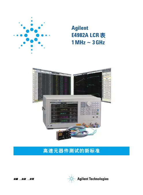
Keysight E4982A LCR 表的性能十分卓越,适用于在 SMD 电感器和 EMI 滤波器等无源元器件的制造过程中提供高频阻抗测试。
E4982A 提供了列表测量等强大功能,不仅适用于制造测试,在研发和质检领域也能大显身手。
E4982A 拥有出色的测量速度和可重复性、优异的测量准确度和宽广的阻抗量程,为高速元器件测试树立了新标杆。
频率
•四种频率选件:1 MHz 至 300 MHz / 500 MHz / 1 GHz / 3 GHz,可升级
测量时间
•高速测量:0.9 ms(模式 1)、2.1 ms(模式 2)、3.7 ms (模式 3)
基本准确度和阻抗量程
•0.8% 基本准确度,测量可重复性超高
•宽广的阻抗量程,从140 mΩ 至4.8 kΩ
更多特性
•SCPI 命令和机械手接口与 4287A 兼容
•小巧的测试头(与 4287A 的尺寸相同)
•列表测量
•通用计算机连通性(GPIB、LAN 和 USB)
E4982A LCR 表的性能十分出色,适用于在 SMD 电感器和 EMI
滤波器等无源元器件的制造过程中提供高频(1 MHz 至 300 MHz / 500 MHz / 1 GHz / 3 GHz)阻抗测试。
Agilent E4980A Precision LCR MeterUser’s GuideEighth EditionFIRMWARE REVISIONSThis manual applies directly to instruments that have the firmware revision A.02.11.For additional information about firmware revisions, see Appendix A.Manufacturing No. E4980-90080June 2010 1981NoticesThe information contained in this document is subject to change without notice.This document contains proprietary information that is protected by copyright. All rights are reserved. No part of this document may be photocopied, reproduced, or translated to another language without the prior written consent of Agilent Technologies.Microsoft®, MS-DOS®, Windows®, Visual C++®, Visual Basic®, VBA®, and Excel®are registered trademarksUNIX is a registered trademark in the U.S. and other countries, licensedexclusively through X/Open Company Limited.Portions ©Copyright 1996, Microsoft Corporation. All rights reserved.© Copyright 2006, 2008, 2010 Agilent TechnologiesManual Printing HistoryThe manual’s printing date and manufacturing number indicate its current edition. The printing date changes when a new edition is printed (minor corrections and updates that are incorporated at reprint do not cause the date to change). The manufacturing number changes when extensive technical changes are incorporated.March 2006 First Edition (manufacturing number: E4980-90000)July 2006 Second Edition (manufacturing number: E4980-90010)November 2006 Third Edition (manufacturing number: E4980-90020)May 2007 Fourth Edition (manufacturing number: E4980-90030)July 2007 Fifth Edition (manufacturing number: E4980-90050)October 2007 Sixth Edition (manufacturing number: E4980-90060)June 2008 Seventh Edition (manufacturing number: E4980-90070)June 2010 Eighth Edition (manufacturing number: E4980-90080)The latest manuals can be downloaded from the following site./find/e4980a/2Safety SummaryThe following general safety precautions must be observed during all phases of operation,service, and repair of this instrument. Failure to comply with these precautions or withspecific WARNINGS elsewhere in this manual may impair the protection provided by theequipment. Such noncompliance would also violate safety standards of design,manufacture, and intended use of the instrument. Agilent Technologies assumes no liabilityfor the customer’s failure to comply with these precautions.NOTE The E4980A complies with INSTALLATION CATEGORY II as well as POLLUTION DEGREE 2 in IEC61010-1. The E4980A is an INDOOR USE product.NOTE The LEDs in the E4980A are Class 1 in accordance with IEC60825-1,CLASS 1 LED PRODUCT•Ground the InstrumentTo avoid electric shock, the instrument chassis and cabinet must be grounded with thesupplied 3-pole power cable’s grounding prong.•DO NOT Operate in an Explosive AtmosphereDo not operate the instrument in the presence of inflammable gasses or fumes.Operation of any electrical instrument in such an environment clearly constitutes asafety hazard.•Keep Away from Live CircuitsOperators must not remove instrument covers. Component replacement and internaladjustments must be made by qualified maintenance personnel only. Do not replacecomponents with the power cable connected. Under certain conditions, dangerousvoltage levels may remain even after the power cable has been disconnected. To avoidinjuries, always disconnect the power and discharge circuits before touching them.•DO NOT Service or Adjust the Instrument AloneDo not attempt internal service or adjustment unless another person, capable ofrendering first aid and resuscitation, is present.•DO NOT Substitute Parts or Modify the InstrumentTo avoid the danger of introducing additional hazards, do not install substitute parts orperform unauthorized modifications to the instrument. Return the instrument to anAgilent Technologies Sales and Service Office for service and repair to ensure thatsafety features are maintained in operational condition.•Dangerous Procedure WarningsWarnings in this manual, such as the example below, precede potentially dangerousprocedures. Instructions contained in the warnings must be followed.WARNING Dangerous voltage levels, capable of causing death, are present in this instrument.Use extreme caution when handling, testing, and adjusting this instrument.34Safety SymbolsGeneral definitions of safety symbols used on the instrument or in manuals are listedbelow.Instruction Manual symbol: the product is marked with this symbol when it is necessary forthe user to refer to the instrument manual.Alternating current.Direct current.On (Supply).Off (Supply).In-position of push-button switch.Out-position of push-button switch.A chassis terminal; a connection to the instrument’s chassis, which includes all exposedmetal structure.Stand-by.WARNING This warning sign denotes a hazard. It calls attention to a procedure, practice, or condition that, if not correctly performed or adhered to, could result in injury or death to personnel.CAUTION This Caution sign denotes a hazard. It calls attention to a procedure, practice, or condition that, if not correctly performed or adhered to, could result in damage to or destruction of part or all of the instrument.NOTE This Note sign denotes important information. It calls attention to a procedure, practice, or condition that is essential for the user to understand.CertificationAgilent Technologies certifies that this product met its published specifications at the timeof shipment from the factory. Agilent Technologies further certifies that its calibrationmeasurements are traceable to the United States National Institute of Standards andTechnology, to the extent allowed by the Institution’s calibration facility or by thecalibration facilities of other International Standards Organization members.WarrantyThis Agilent Technologies instrument product is warranted against defects in material andworkmanship for a period corresponding to the individual warranty periods of itscomponent products. Instruments are warranted for a period of one year. During thewarranty period, Agilent Technologies will, at its option, either repair or replace productsthat prove to be defective.For warranty service or repair, this product must be returned to a service facility designatedby Agilent Technologies. The buyer shall prepay shipping charges to Agilent Technologies,and Agilent Technologies shall pay shipping charges to return the product to the Buyer.However, the Buyer shall pay all shipping charges, duties, and taxes for products returnedto Agilent Technologies from another country.Agilent Technologies warrants that its software and firmware designated by AgilentTechnologies for use with an instrument will execute its programming instruction whenproperly installed on that instrument. Agilent Technologies does not warrant that theoperation of the instrument, or software, or firmware, will be uninterrupted or error free.Limitation of WarrantyThe foregoing warranty shall not apply to defects resulting from improper or inadequatemaintenance by the Buyer, Buyer-supplied software or interfacing, unauthorizedmodification or misuse, operation outside the environmental specifications for the product,or improper site preparation or maintenance.IMPORTANT No other warranty is expressed or implied. Agilent Technologies specifically disclaims the implied warranties of merchantability and fitness for a particular purpose.Exclusive RemediesThe remedies provided herein are the Buyer’s sole and exclusive remedies. AgilentTechnologies shall not be liable for any direct, indirect, special, incidental, orconsequential damages, whether based on contract, tort, or any other legal theory.5AssistanceProduct maintenance agreements and other customer assistance agreements are availablefor Agilent Technologies products.For any assistance, contact your nearest Agilent Technologies Sales and Service Office.Addresses are provided at the back of this manual.Typeface ConventionsSample (bold)Boldface type is used for emphasis.Sample (Italic)Italic type is used for emphasis and manual title.[Sample] key Indicates a hardkey (key on the front panel orexternal keyboard) labeled “Sample.” “key” maybe omitted.Sample menu/button/box Indicates a menu/button/box on the screen labeled“Sample” that can be selected/executed byclicking “menu,” “button,” or “box,” may beomitted.Sample 1 - Sample 2 - Sample 3Indicates a sequential operation of Sample 1,Sample 2, and Sample 3 (menu, button, or box).“-” may be omitted.Documentation MapThe following manuals are available for the Agilent E4980A.•User’s Guide (Manufacturing Number E4980-900x0, attached to Option ABA,English)This manual describes most of the basic information on the E4980A. It provides adetailed operation procedure for each function (from the function overview to systemsettings), measurement examples, options, accessories, specifications, GPIBcommands, function lists by softkeys, and error messages.NOTE The number position shown by “x” in the manufacturing number above indicates theedition number.6Sample ProgramsThe customer shall have the personal, nontransferable rights to use, copy, or modify SAMPLE PROGRAMS in this manual for the Customer’s internal operations. The customer shall use the SAMPLE PROGRAMS solely and exclusively for their own purpose and shall not license, lease, market, or distribute the SAMPLE PROGRAMS or modifications of any part thereof.Agilent Technologies shall not be liable for the quality, performance, or behavior of the SAMPLE PROGRAMS. Agilent Technologies especially disclaims that the operation of the SAMPLE PROGRAMS shall be uninterrupted or error free. The SAMPLE PROGRAMS are provided AS IS.AGILENT TECHNOLOGIES DISCLAIMS IMPLIED WARRANTIES OF MERCHANTABILITY AND FITNESS FOR A PARTICULAR PURPOSE.Agilent Technologies shall not be liable for any infringement of any patent, trademark, copyright, or other proprietary rights by the SAMPLE PROGRAMS or their use. Agilent Technologies does not warrant that the SAMPLE PROGRAMS are free from infringements of such rights of third parties. However, Agilent Technologies will not knowingly infringe or deliver software that infringes the patent, trademark, copyright, or other proprietary right of a third party.78Contents 1.Unpacking and PreparationChecking the Shipment. . . . . . . . . . . . . . . . . . . . . . . . . . . . . . . . . . . . . . . . . . . . . . . . . . . . . . . . . . . . . . . . . 23 Preparations before Use . . . . . . . . . . . . . . . . . . . . . . . . . . . . . . . . . . . . . . . . . . . . . . . . . . . . . . . . . . . . . . . . 26 Verifying the Power Supply . . . . . . . . . . . . . . . . . . . . . . . . . . . . . . . . . . . . . . . . . . . . . . . . . . . . . . . . . . . 26 Setting up the Fuse . . . . . . . . . . . . . . . . . . . . . . . . . . . . . . . . . . . . . . . . . . . . . . . . . . . . . . . . . . . . . . . . . . 26 Verifying and Connecting the Power Cable . . . . . . . . . . . . . . . . . . . . . . . . . . . . . . . . . . . . . . . . . . . . . . . 27 How to Remove the Handle . . . . . . . . . . . . . . . . . . . . . . . . . . . . . . . . . . . . . . . . . . . . . . . . . . . . . . . . . . . . . 29 Caution when Using the Handle. . . . . . . . . . . . . . . . . . . . . . . . . . . . . . . . . . . . . . . . . . . . . . . . . . . . . . . . . . 30 Environmental Requirements. . . . . . . . . . . . . . . . . . . . . . . . . . . . . . . . . . . . . . . . . . . . . . . . . . . . . . . . . . . . 31 Operating Environments. . . . . . . . . . . . . . . . . . . . . . . . . . . . . . . . . . . . . . . . . . . . . . . . . . . . . . . . . . . . . . 31 Ventilation Requirements . . . . . . . . . . . . . . . . . . . . . . . . . . . . . . . . . . . . . . . . . . . . . . . . . . . . . . . . . . . . . 32 Protection Against Electrostatic Discharge (ESD) . . . . . . . . . . . . . . . . . . . . . . . . . . . . . . . . . . . . . . . . . . 33 Ensuring Adequate Free Space around the LCR meter for Immediate Disconnection of the Power Cable in Case of Emergency . . . . . . . . . . . . . . . . . . . . . . . . . . . . . . . . . . . . . . . . . . . . . . . . . . . . . . . . . . . . . . . . . . 33 Starting the E4980A . . . . . . . . . . . . . . . . . . . . . . . . . . . . . . . . . . . . . . . . . . . . . . . . . . . . . . . . . . . . . . . . . . . 34 Turning the Power ON and OFF. . . . . . . . . . . . . . . . . . . . . . . . . . . . . . . . . . . . . . . . . . . . . . . . . . . . . . . . 34 Disconnecting from the Supply Source. . . . . . . . . . . . . . . . . . . . . . . . . . . . . . . . . . . . . . . . . . . . . . . . . . . 35 2.OverviewProduct Introduction. . . . . . . . . . . . . . . . . . . . . . . . . . . . . . . . . . . . . . . . . . . . . . . . . . . . . . . . . . . . . . . . . . . 38 Front Panel: Names and Functions of Parts . . . . . . . . . . . . . . . . . . . . . . . . . . . . . . . . . . . . . . . . . . . . . . . . . 391. Power switch. . . . . . . . . . . . . . . . . . . . . . . . . . . . . . . . . . . . . . . . . . . . . . . . . . . . . . . . . . . . . . . . . . . . . 402. LCD . . . . . . . . . . . . . . . . . . . . . . . . . . . . . . . . . . . . . . . . . . . . . . . . . . . . . . . . . . . . . . . . . . . . . . . . . . . 403. Softkeys. . . . . . . . . . . . . . . . . . . . . . . . . . . . . . . . . . . . . . . . . . . . . . . . . . . . . . . . . . . . . . . . . . . . . . . . . 404. Menu keys. . . . . . . . . . . . . . . . . . . . . . . . . . . . . . . . . . . . . . . . . . . . . . . . . . . . . . . . . . . . . . . . . . . . . . . 405. Cursor keys . . . . . . . . . . . . . . . . . . . . . . . . . . . . . . . . . . . . . . . . . . . . . . . . . . . . . . . . . . . . . . . . . . . . . . 406. Entry keys . . . . . . . . . . . . . . . . . . . . . . . . . . . . . . . . . . . . . . . . . . . . . . . . . . . . . . . . . . . . . . . . . . . . . . . 407. LED indicator . . . . . . . . . . . . . . . . . . . . . . . . . . . . . . . . . . . . . . . . . . . . . . . . . . . . . . . . . . . . . . . . . . . . 418. Preset key . . . . . . . . . . . . . . . . . . . . . . . . . . . . . . . . . . . . . . . . . . . . . . . . . . . . . . . . . . . . . . . . . . . . . . . 419. Trigger key . . . . . . . . . . . . . . . . . . . . . . . . . . . . . . . . . . . . . . . . . . . . . . . . . . . . . . . . . . . . . . . . . . . . . . 4110. DC Bias key . . . . . . . . . . . . . . . . . . . . . . . . . . . . . . . . . . . . . . . . . . . . . . . . . . . . . . . . . . . . . . . . . . . . 4111. DC Source key. . . . . . . . . . . . . . . . . . . . . . . . . . . . . . . . . . . . . . . . . . . . . . . . . . . . . . . . . . . . . . . . . . . 4112. UNKNOWN terminals . . . . . . . . . . . . . . . . . . . . . . . . . . . . . . . . . . . . . . . . . . . . . . . . . . . . . . . . . . . . 4113. Front USB port . . . . . . . . . . . . . . . . . . . . . . . . . . . . . . . . . . . . . . . . . . . . . . . . . . . . . . . . . . . . . . . . . . 4214. Ground terminal . . . . . . . . . . . . . . . . . . . . . . . . . . . . . . . . . . . . . . . . . . . . . . . . . . . . . . . . . . . . . . . . . 4215. DC Source terminal. . . . . . . . . . . . . . . . . . . . . . . . . . . . . . . . . . . . . . . . . . . . . . . . . . . . . . . . . . . . . . . 42Rear Panel: Names and Functions of Parts. . . . . . . . . . . . . . . . . . . . . . . . . . . . . . . . . . . . . . . . . . . . . . . . . . 431. GPIB Interface Connector. . . . . . . . . . . . . . . . . . . . . . . . . . . . . . . . . . . . . . . . . . . . . . . . . . . . . . . . . . . 432. Interface Connector. . . . . . . . . . . . . . . . . . . . . . . . . . . . . . . . . . . . . . . . . . . . . . . . . . . . . . . . . . . . . . . . 433. USB (USBTMC) Interface Port . . . . . . . . . . . . . . . . . . . . . . . . . . . . . . . . . . . . . . . . . . . . . . . . . . . . . . 444. LAN Port. . . . . . . . . . . . . . . . . . . . . . . . . . . . . . . . . . . . . . . . . . . . . . . . . . . . . . . . . . . . . . . . . . . . . . . . 445. External Trigger Input Connector. . . . . . . . . . . . . . . . . . . . . . . . . . . . . . . . . . . . . . . . . . . . . . . . . . . . . 446. Serial Number Plate . . . . . . . . . . . . . . . . . . . . . . . . . . . . . . . . . . . . . . . . . . . . . . . . . . . . . . . . . . . . . . . 447. Power Cable Receptacle (to LINE). . . . . . . . . . . . . . . . . . . . . . . . . . . . . . . . . . . . . . . . . . . . . . . . . . . . 448. Fan. . . . . . . . . . . . . . . . . . . . . . . . . . . . . . . . . . . . . . . . . . . . . . . . . . . . . . . . . . . . . . . . . . . . . . . . . . . . . 45Screen Area: Names and Functions of Parts. . . . . . . . . . . . . . . . . . . . . . . . . . . . . . . . . . . . . . . . . . . . . . . . . 461. Display Page Area. . . . . . . . . . . . . . . . . . . . . . . . . . . . . . . . . . . . . . . . . . . . . . . . . . . . . . . . . . . . . . . . . 462. Comment Line Area . . . . . . . . . . . . . . . . . . . . . . . . . . . . . . . . . . . . . . . . . . . . . . . . . . . . . . . . . . . . . . . 463. Softkey Area . . . . . . . . . . . . . . . . . . . . . . . . . . . . . . . . . . . . . . . . . . . . . . . . . . . . . . . . . . . . . . . . . . . . . 479Contents4. Measurement Data/Conditions Area. . . . . . . . . . . . . . . . . . . . . . . . . . . . . . . . . . . . . . . . . . . . . . . . . . . 475. Input Line Area. . . . . . . . . . . . . . . . . . . . . . . . . . . . . . . . . . . . . . . . . . . . . . . . . . . . . . . . . . . . . . . . . . . 486. System Message Area. . . . . . . . . . . . . . . . . . . . . . . . . . . . . . . . . . . . . . . . . . . . . . . . . . . . . . . . . . . . . . 487. Status Display Area. . . . . . . . . . . . . . . . . . . . . . . . . . . . . . . . . . . . . . . . . . . . . . . . . . . . . . . . . . . . . . . . 48Basic Operation . . . . . . . . . . . . . . . . . . . . . . . . . . . . . . . . . . . . . . . . . . . . . . . . . . . . . . . . . . . . . . . . . . . . . . 49 How to Use Cursor Keys . . . . . . . . . . . . . . . . . . . . . . . . . . . . . . . . . . . . . . . . . . . . . . . . . . . . . . . . . . . . . 49 How to Use Skip Keys . . . . . . . . . . . . . . . . . . . . . . . . . . . . . . . . . . . . . . . . . . . . . . . . . . . . . . . . . . . . . . . 50 3.Display FormatMEAS DISPLAY Page. . . . . . . . . . . . . . . . . . . . . . . . . . . . . . . . . . . . . . . . . . . . . . . . . . . . . . . . . . . . . . . . . 52 Measurement Function. . . . . . . . . . . . . . . . . . . . . . . . . . . . . . . . . . . . . . . . . . . . . . . . . . . . . . . . . . . . . . . 54 Impedance range. . . . . . . . . . . . . . . . . . . . . . . . . . . . . . . . . . . . . . . . . . . . . . . . . . . . . . . . . . . . . . . . . . . . 57 Test Frequency . . . . . . . . . . . . . . . . . . . . . . . . . . . . . . . . . . . . . . . . . . . . . . . . . . . . . . . . . . . . . . . . . . . . . 64 Test Signal Level. . . . . . . . . . . . . . . . . . . . . . . . . . . . . . . . . . . . . . . . . . . . . . . . . . . . . . . . . . . . . . . . . . . . 66 DC Bias. . . . . . . . . . . . . . . . . . . . . . . . . . . . . . . . . . . . . . . . . . . . . . . . . . . . . . . . . . . . . . . . . . . . . . . . . . . 69 Measurement Time Mode. . . . . . . . . . . . . . . . . . . . . . . . . . . . . . . . . . . . . . . . . . . . . . . . . . . . . . . . . . . . . 73 Display Setting for Measurement Results . . . . . . . . . . . . . . . . . . . . . . . . . . . . . . . . . . . . . . . . . . . . . . . . 74 Displaying Errors instead of Measurement Results . . . . . . . . . . . . . . . . . . . . . . . . . . . . . . . . . . . . . . . . . 76 Monitor Information. . . . . . . . . . . . . . . . . . . . . . . . . . . . . . . . . . . . . . . . . . . . . . . . . . . . . . . . . . . . . . . . . 79 BIN NO. DISPLAY Page. . . . . . . . . . . . . . . . . . . . . . . . . . . . . . . . . . . . . . . . . . . . . . . . . . . . . . . . . . . . . . . 80 Comparator Function ON/OFF. . . . . . . . . . . . . . . . . . . . . . . . . . . . . . . . . . . . . . . . . . . . . . . . . . . . . . . . . 81 BIN COUNT DISPLAY Page . . . . . . . . . . . . . . . . . . . . . . . . . . . . . . . . . . . . . . . . . . . . . . . . . . . . . . . . . . . 82 Counter Function . . . . . . . . . . . . . . . . . . . . . . . . . . . . . . . . . . . . . . . . . . . . . . . . . . . . . . . . . . . . . . . . . . . 83 LIST SWEEP DISPLAY Page. . . . . . . . . . . . . . . . . . . . . . . . . . . . . . . . . . . . . . . . . . . . . . . . . . . . . . . . . . . 84 Sweep Mode. . . . . . . . . . . . . . . . . . . . . . . . . . . . . . . . . . . . . . . . . . . . . . . . . . . . . . . . . . . . . . . . . . . . . . . 85 DISPLAY BLANK Page . . . . . . . . . . . . . . . . . . . . . . . . . . . . . . . . . . . . . . . . . . . . . . . . . . . . . . . . . . . . . . . 87 4.Configuring Measurement Conditions (Display and Function Related Settings)Initializing the Instrument . . . . . . . . . . . . . . . . . . . . . . . . . . . . . . . . . . . . . . . . . . . . . . . . . . . . . . . . . . . . . . 90 MEAS SETUP page. . . . . . . . . . . . . . . . . . . . . . . . . . . . . . . . . . . . . . . . . . . . . . . . . . . . . . . . . . . . . . . . . . . 91 Comment line . . . . . . . . . . . . . . . . . . . . . . . . . . . . . . . . . . . . . . . . . . . . . . . . . . . . . . . . . . . . . . . . . . . . . . 93 Trigger mode. . . . . . . . . . . . . . . . . . . . . . . . . . . . . . . . . . . . . . . . . . . . . . . . . . . . . . . . . . . . . . . . . . . . . . . 94 Automatic level control . . . . . . . . . . . . . . . . . . . . . . . . . . . . . . . . . . . . . . . . . . . . . . . . . . . . . . . . . . . . . . 96 DC Bias Current Isolation. . . . . . . . . . . . . . . . . . . . . . . . . . . . . . . . . . . . . . . . . . . . . . . . . . . . . . . . . . . . 100 Averaging Factor. . . . . . . . . . . . . . . . . . . . . . . . . . . . . . . . . . . . . . . . . . . . . . . . . . . . . . . . . . . . . . . . . . . 101 Trigger Delay Time. . . . . . . . . . . . . . . . . . . . . . . . . . . . . . . . . . . . . . . . . . . . . . . . . . . . . . . . . . . . . . . . . 102 Step Delay Time . . . . . . . . . . . . . . . . . . . . . . . . . . . . . . . . . . . . . . . . . . . . . . . . . . . . . . . . . . . . . . . . . . . 104 DC Bias V oltage Monitor . . . . . . . . . . . . . . . . . . . . . . . . . . . . . . . . . . . . . . . . . . . . . . . . . . . . . . . . . . . . 106 DC Bias Current Monitor. . . . . . . . . . . . . . . . . . . . . . . . . . . . . . . . . . . . . . . . . . . . . . . . . . . . . . . . . . . . 107 DCR Range. . . . . . . . . . . . . . . . . . . . . . . . . . . . . . . . . . . . . . . . . . . . . . . . . . . . . . . . . . . . . . . . . . . . . . . 108 DCI Range . . . . . . . . . . . . . . . . . . . . . . . . . . . . . . . . . . . . . . . . . . . . . . . . . . . . . . . . . . . . . . . . . . . . . . . 109 DC Source. . . . . . . . . . . . . . . . . . . . . . . . . . . . . . . . . . . . . . . . . . . . . . . . . . . . . . . . . . . . . . . . . . . . . . . . 110 Automatic Bias Polarity Control . . . . . . . . . . . . . . . . . . . . . . . . . . . . . . . . . . . . . . . . . . . . . . . . . . . . . . 111 Deviation Measurement . . . . . . . . . . . . . . . . . . . . . . . . . . . . . . . . . . . . . . . . . . . . . . . . . . . . . . . . . . . . . 113 CORRECTION page . . . . . . . . . . . . . . . . . . . . . . . . . . . . . . . . . . . . . . . . . . . . . . . . . . . . . . . . . . . . . . . . . 115 To set the correct function to on or off . . . . . . . . . . . . . . . . . . . . . . . . . . . . . . . . . . . . . . . . . . . . . . . . . . 116 The correction functions of the E4980A are operated as follows:. . . . . . . . . . . . . . . . . . . . . . . . . . . . . 117 Open Correction . . . . . . . . . . . . . . . . . . . . . . . . . . . . . . . . . . . . . . . . . . . . . . . . . . . . . . . . . . . . . . . . . . . 118 10Short Correction . . . . . . . . . . . . . . . . . . . . . . . . . . . . . . . . . . . . . . . . . . . . . . . . . . . . . . . . . . . . . . . . . . . 121 Correction Based on User-Specified Frequency Points . . . . . . . . . . . . . . . . . . . . . . . . . . . . . . . . . . . . . 123 Relationships between Correction Based on All Frequency Points and Correction Based on SpecifiedFrequency Points. . . . . . . . . . . . . . . . . . . . . . . . . . . . . . . . . . . . . . . . . . . . . . . . . . . . . . . . . . . . . . . . . . . 127 Reading/Writing Correction Data. . . . . . . . . . . . . . . . . . . . . . . . . . . . . . . . . . . . . . . . . . . . . . . . . . . . . . 129 Measurement Functions for the Standard . . . . . . . . . . . . . . . . . . . . . . . . . . . . . . . . . . . . . . . . . . . . . . . . 130 Selecting Single/Multiple Correction Mode. . . . . . . . . . . . . . . . . . . . . . . . . . . . . . . . . . . . . . . . . . . . . . 131 Selecting the Cable Length. . . . . . . . . . . . . . . . . . . . . . . . . . . . . . . . . . . . . . . . . . . . . . . . . . . . . . . . . . . 132 LIMIT TABLE SETUP Page . . . . . . . . . . . . . . . . . . . . . . . . . . . . . . . . . . . . . . . . . . . . . . . . . . . . . . . . . . . 133 Parameter Swap Feature . . . . . . . . . . . . . . . . . . . . . . . . . . . . . . . . . . . . . . . . . . . . . . . . . . . . . . . . . . . . . 134 Comparator Limit Mode . . . . . . . . . . . . . . . . . . . . . . . . . . . . . . . . . . . . . . . . . . . . . . . . . . . . . . . . . . . . . 136 Tolerance Mode Nominal Value . . . . . . . . . . . . . . . . . . . . . . . . . . . . . . . . . . . . . . . . . . . . . . . . . . . . . . . 138 Turning On/Off the Comparator . . . . . . . . . . . . . . . . . . . . . . . . . . . . . . . . . . . . . . . . . . . . . . . . . . . . . . . 139 Turning On/Off the Auxiliary Bin. . . . . . . . . . . . . . . . . . . . . . . . . . . . . . . . . . . . . . . . . . . . . . . . . . . . . . 140 Beep Feature . . . . . . . . . . . . . . . . . . . . . . . . . . . . . . . . . . . . . . . . . . . . . . . . . . . . . . . . . . . . . . . . . . . . . . 142 Lower and Upper Limits . . . . . . . . . . . . . . . . . . . . . . . . . . . . . . . . . . . . . . . . . . . . . . . . . . . . . . . . . . . . 143 LIST SWEEP SETUP Page . . . . . . . . . . . . . . . . . . . . . . . . . . . . . . . . . . . . . . . . . . . . . . . . . . . . . . . . . . . . 146 Sweep Mode . . . . . . . . . . . . . . . . . . . . . . . . . . . . . . . . . . . . . . . . . . . . . . . . . . . . . . . . . . . . . . . . . . . . . . 147 List Sweep Parameters . . . . . . . . . . . . . . . . . . . . . . . . . . . . . . . . . . . . . . . . . . . . . . . . . . . . . . . . . . . . . . 148 Sweep Points and Limit Modes. . . . . . . . . . . . . . . . . . . . . . . . . . . . . . . . . . . . . . . . . . . . . . . . . . . . . . . . 149 Sweep Parameter Auto-completion. . . . . . . . . . . . . . . . . . . . . . . . . . . . . . . . . . . . . . . . . . . . . . . . . . . . . 152 5.System ConfigurationsSYSTEM INFO Page . . . . . . . . . . . . . . . . . . . . . . . . . . . . . . . . . . . . . . . . . . . . . . . . . . . . . . . . . . . . . . . . . 156 Bias Current Interface. . . . . . . . . . . . . . . . . . . . . . . . . . . . . . . . . . . . . . . . . . . . . . . . . . . . . . . . . . . . . . . 157 Handler Interface. . . . . . . . . . . . . . . . . . . . . . . . . . . . . . . . . . . . . . . . . . . . . . . . . . . . . . . . . . . . . . . . . . . 158 Scanner Interface. . . . . . . . . . . . . . . . . . . . . . . . . . . . . . . . . . . . . . . . . . . . . . . . . . . . . . . . . . . . . . . . . . . 159 Monitor Information . . . . . . . . . . . . . . . . . . . . . . . . . . . . . . . . . . . . . . . . . . . . . . . . . . . . . . . . . . . . . . . . 159 SYSTEM CONFIG Page . . . . . . . . . . . . . . . . . . . . . . . . . . . . . . . . . . . . . . . . . . . . . . . . . . . . . . . . . . . . . . 160 Turning On/Off the Beep Feature . . . . . . . . . . . . . . . . . . . . . . . . . . . . . . . . . . . . . . . . . . . . . . . . . . . . . . 161 Changing the Beep Tone . . . . . . . . . . . . . . . . . . . . . . . . . . . . . . . . . . . . . . . . . . . . . . . . . . . . . . . . . . . . 162 Changing the Beep Tone . . . . . . . . . . . . . . . . . . . . . . . . . . . . . . . . . . . . . . . . . . . . . . . . . . . . . . . . . . . . 163 Configuring the Time Zone. . . . . . . . . . . . . . . . . . . . . . . . . . . . . . . . . . . . . . . . . . . . . . . . . . . . . . . . . . . 164 Configuring the System Date . . . . . . . . . . . . . . . . . . . . . . . . . . . . . . . . . . . . . . . . . . . . . . . . . . . . . . . . . 165 Configuring the GPIB Address. . . . . . . . . . . . . . . . . . . . . . . . . . . . . . . . . . . . . . . . . . . . . . . . . . . . . . . . 167 Configuring the LAN IP address. . . . . . . . . . . . . . . . . . . . . . . . . . . . . . . . . . . . . . . . . . . . . . . . . . . . . . . 168 SELF TEST Page . . . . . . . . . . . . . . . . . . . . . . . . . . . . . . . . . . . . . . . . . . . . . . . . . . . . . . . . . . . . . . . . . . . . 171 Choosing a Test Item. . . . . . . . . . . . . . . . . . . . . . . . . . . . . . . . . . . . . . . . . . . . . . . . . . . . . . . . . . . . . . . . 172 SERVICE Page. . . . . . . . . . . . . . . . . . . . . . . . . . . . . . . . . . . . . . . . . . . . . . . . . . . . . . . . . . . . . . . . . . . . . . 173 Monitor Information . . . . . . . . . . . . . . . . . . . . . . . . . . . . . . . . . . . . . . . . . . . . . . . . . . . . . . . . . . . . . . . . 174 Saving the System Information into External Memory . . . . . . . . . . . . . . . . . . . . . . . . . . . . . . . . . . . . . 174 6.Save/RecallOverview of Save/Recall Functionality . . . . . . . . . . . . . . . . . . . . . . . . . . . . . . . . . . . . . . . . . . . . . . . . . . . 176 Save Methods and Their Uses. . . . . . . . . . . . . . . . . . . . . . . . . . . . . . . . . . . . . . . . . . . . . . . . . . . . . . . . . 176 Folder/File Structure on USB Memory. . . . . . . . . . . . . . . . . . . . . . . . . . . . . . . . . . . . . . . . . . . . . . . . . . 176 USB Memory Notes . . . . . . . . . . . . . . . . . . . . . . . . . . . . . . . . . . . . . . . . . . . . . . . . . . . . . . . . . . . . . . . . 177 Saving/Recalling Instrument Configuration States. . . . . . . . . . . . . . . . . . . . . . . . . . . . . . . . . . . . . . . . . . . 178。
Agilent E4980A 精密LCR 表Agilent E4980A 精密LCR 表和4294A 精密阻抗分析仪的MEMS 测试应用指南Agilent 4294A 精密阻抗分析仪目录利用Agilent E4980A精密LCR表提高MEMS电容传感器的测试效率 (3)利用Agilent E4980A精密LCR表表征电磁MEMS光学开关执行器 (5)利用Agilent E4980A精密LCR表表征电磁MEMS光学扫描仪 (6)利用Agilent E4980A精密LCR表提高MEMS静电执行器的测试效率 (8)利用Agilent 4294A精密阻抗分析仪精确评测MEMS压电传感器和执行器 (11)利用Agilent 4294A和E4991A阻抗分析仪表征MEMS磁阻抗传感器 (14)23简介本文将简要介绍Agilent E4980A 的特性,以及它如何显著提高MEMS 电容传感器的测试效率。
Agilent E4980A 精密LCR 表Agilent E4980A 精密LCR 表拥有出色的精度和测试速度,是进行研发和生产测试的理想工具。
MEMS 电容传感器对于MEMS 传感器(例如压力传感器或加速传感器)来说,检测机械位移的一个主要方法就是检测机械位移引起的电容变化(图1)。
电容器是在基底(substrate )上采用微工艺制造的,电容器电极的位移可通过检测电容变化得出。
图1. MEMS 电容传感器的工作原理传感器电容的高精度测量当执行器的位置变化很小时,其电容变化也很小,所以测量MEMS 电容传感器的电容需要达到亚飞法拉(千万亿分之一法拉)级精度。
因此,电容测量要求仪器的测量精度和可重复性都非常高。
Agilent E4980A 精密LCR 表具有阿托(10-18)法拉级可重复性(σ<1 fF )的电容测量能力,是测试MEMS 电容传感器的理想工具。
E4980A 能够不受MEMS 结构谐振的影响进行电容测试,因为高达2 MHz 的频率范围已远离机械结构(例如可动电极)的谐振频率(通常为几十KHz )(见图2)。