FLA-502说明书(含通信协议)
- 格式:doc
- 大小:2.06 MB
- 文档页数:30

500 SERIES MICROPHONE PREAMPLIFIER 502 500 Series Modular Midas Microphone Preamplifier with Classic XL4 FiltersV 1.0带有此标志的终端设备具有强大的电流, 存在触电危险。
仅限使用带有 1/4'' TS 或扭锁式插头的高品质专业扬声器线。
所有的安装或调整均须由合格的专业人员进行。
此标志提醒您,产品内存在未绝缘的危险电压, 有 触电危险。
此标志提醒您查阅所附的重要的使用及维修说明。
请阅读有关手册。
小心为避免触电危险, 请勿打开机顶盖 (或背面挡板)。
设备内没有可供用户维修使用的部件。
请将维修事项交由合格的专业人员进行。
小心为避免着火或触电危险, 请勿将此设备置于雨淋或潮湿中。
此设备也不可受液体滴溅, 盛有液体的容器也不可置于其上, 如花瓶等。
小心维修说明仅是给合格的专业维修人员使用的。
为 避免触电危险, 除了使用说明书提到的以外, 请勿进行任何其它维修。
所有维修均须由合格的专业人员进行。
1. 请阅读这些说明。
2. 请妥善保存这些说明。
3. 请注意所有的警示。
4. 请遵守所有的说明。
5. 请勿在靠近水的地方使用本产品。
6. 请用干布清洁本产品。
7. 请勿堵塞通风口。
安装本产品时请遵照厂家的说明。
8. 请勿将本产品安装在热源附近, 如 暖气片, 炉子或其它产生热量的设备 ( 包括功放器)。
9. 请勿移除极性插头或接地插头的安全装置。
接地插头是由两个插塞接点及一个接地头构成。
若随货提供的插头不适合您的插座, 请找电工更换一个合适的插座。
10. 妥善保护电源线, 使其不被践踏或刺破, 尤其注意电源插头、多用途插座及设备连接处。
11. 请只使用厂家指定的附属设备和配 件。
12. 请只使用厂家指定的或随货销售的手推车, 架子, 三 角架, 支架和桌子。
若使用手推车来搬运设备, 请注意安全放置设备, 以 避免手推车和设备倾倒而受伤。
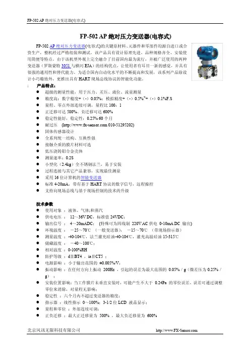
FP-502 AP绝对压力变送器(电容式)FP-502 AP绝对压力变送器(电容式)的关键原材料、元器件和零部件均源自进口或合资生产,整机经过严格组装和测试。
该产品具有设计原理先进、品种规格齐全、安装使用简便等特点。
由于该机型外观上完全融合了目前国内最为流行,并被广泛使用的两种变送器(罗斯蒙特3051与横河EJA)的结构优点,让使用者有耳目一新的感觉,并具有很强的通用性和替代能力。
为适合国内自动化水平的不断提高和发展,该系列产品除设计小巧精致外,更推出具有HART现场总线协议的智能化功能。
; 产品特点:●超级的测量性能,用于压力、差压、液位、流量测量●精度高:数字精度+(-)0.05%;模拟精度+(-)0.5%~+(-)0.1%F.S●量程、零点外部连续可调,量程比100:1●正迁移可达500%、负迁移可达600%●稳定性能好,稳定性:0.25% 60个月●耐过压( 010-********)●固体传感器设计●全系列统一结构、互换性强●接触介质的膜片材料可选●低压浇铸铝合金壳体●测量速率:0.2S●小型化(2.4kg)全不锈钢法兰,易于安装●过程连接与其它产品兼容,实现最佳测量●采用16位计算机的智能变送器●标准4-20mA,带有基于HART协议的数字信号,远程操控●支持向现场总线与基于现场控制的技术的升级技术参数●使用对象:液体、气体;和蒸汽●供电电压:12~36V DC,标准值24VDC;●输出信号:4~20mADC;(特殊可为四线制220V AC供电0-10mA DC 输出)●环境温度:-25~70℃(一般变送器),-15~70℃(带现场指示器)●测量温度:-40-104℃,法兰灌充硅油-40-104℃,灌充高温硅油15-315℃●储藏温度:-40~100℃;●相对温度:0-100%RH●防护等级:dⅡBT4 ,iaⅡCT5 ;●电源影响:小于输出范围的±0.005%/V;●振动影响:在任何方向上振动200Hz ,引起的误差为最大范围的0.05%/g(微差压为0.25%/g);●安装位置影响:当工作膜片未垂直安装时,可能产生不大于0.24Pa 的零位误差,误差可通过调整零位来消除,对量程无影响;●稳定性:六个月内不超过变送器的精度;●指示器:线性指示0~100%;3-1/2位LCD 液晶显示;●量程和零位:外部连续可调;●正负迁移:最大正迁移量为500% ,最大负迁移量为600%材料隔离膜片:316L不锈钢,哈式合金-C ,蒙耐尔合金,钽排气/排液阀:316L不锈钢,哈式合金-C,蒙耐尔合金法兰和接头:316L不锈钢,哈式合金-C ,蒙耐尔合金"O" 型圈:氟橡胶灌充液:硅油惰性油螺栓:316L 不锈钢电子壳体:低铜铝合金产品选型( 010-********)外形尺寸图。


PLC-502PLC联网宝使用手册北京北科驿唐科技有限公司北京市海淀区丰贤中路7号北科产业园3号楼2层TEL:4008-909-611FAX:************网址:©版权所有2005-2023本手册适用于如下型号:型号说明PLC-502-W0支持WIFI及WAN有线网络,默认使用WAN有线网络PLC-502-W4支持4G/3G/2G无线网络(七模)和WIFI/WAN网络,默认使用4G无线网络PLC-502-W4G支持4G/3G/2G无线网络(七模)、WIFI以及WAN有线网络,默认使用4G无线网络,支持GPS定位目录第一章产品介绍 (3)1.1产品简介 (3)1.2产品外观 (4)1.3标准配件 (5)1.4安装尺寸 (7)1.5工作原理 (8)1.6规格参数 (9)1.6.1技术参数 (9)1.6.2指示灯说明 (10)1.6.3串口定义 (11)1.6.4RESET按钮 (11)1.7典型应用 (12)第二章设备配置 (14)2.1配置方法 (14)2.1.1准备工作 (14)2.1.2配置PLC-502 (14)2.2配置参数介绍 (21)2.3恢复出厂设置 (23)2.4固件更新 (23)2.5远程配置 (25)附录1:PLC-502网口通功能实现PLC远程程序更新案例 (29)1.注册驿云账号 (29)2.配置PLC-502 (30)3.设置网口通软件 (30)4.通过网口通远程访问PLC-502配置界面 (34)附录2:PLC-502串口功能实现PLC远程程序更新案例 (38)1.注册联网宝驿云账号 (38)2.配置PLC-502 (39)3.配置串口通软件 (40)附录3:配置PLC-502通过4G无线网络上网 (43)附录4:配置PLC-502通过有线/WIFI接入网络 (44)附录5:用PLC-502网口收发短信及短信数据格式 (54)附录6:PLC-502结合VNC软件实现设备远程控制 (58)附录7:网口通结合工业联网宝虚网映射功能实现下位机设备相同IP地址的远程访问 (65)附录8:PLC-502GPS定位信息查询设置及GPS位置数据查询 (69)附录9:设置电脑/网口设备通过联网宝上网 (71)附录10:工业联网宝MODBUS TCP接口说明 (75)附录11:工业联网宝DMZ转发增强功能 (76)第一章产品介绍本章主要介绍PLC-502的外观、配件、规格参数和使用原理。

版权声明是深圳市联科通网络技术有限公司注册商标。
文中提及的其它商标或商品名称均是深圳市联科通网络技术有限公司的商标或注册商标。
本产品的所有组件,包括硬件和软件,其版权属深圳市联科通网络技术有限公司所有,在未经过深圳市联科通网络技术有限公司许可的情况下,不得任意拷贝、抄袭、仿制或翻译成其它语言。
本手册中的所有图片和产品参数仅供参考,随着软件或硬件的升级会略有差异,如有变更,恕不另行通知,如需了解更多产品信息,请登录我们公司网站:目录版权声明 (2)目录 (3)第I部分产品简介 (5)1包装清单 (5)2面板指示灯及接口说明 (5)3产品规格 (7)第II部分快速上网设置 (8)1物理连接 (8)2有线连接电脑配置 (8)2.1 Win 7系统电脑设置 (8)2.2 XP 系统电脑设置 (13)3无线连接电脑配置 (16)3.1 Win7 系统无线连接 (16)3.2 XP 系统无线连接 (19)第III部分高级设置 (23)1登录 (23)2系统状态 (24)2.1 系统状态 (24)2.2 无线状态 (25)2.3 AP报文统计 (26)2.4 无线客户端 (27)3LAN口设置 (28)4DHCP服务器 (28)4.1 DHCP服务器 (28)4.2 DHCP连接列表 (29)5无线设置 (30)5.1 基本设置 (30)5.2 射频设置 (33)5.3 高级设置 (35)5.4 访问控制 (36)6SNMP设置 (37)7系统工具 (38)7.1 设备维护 (38)7.2 时间管理 (39)7.3 日志查看 (40)7.4 配置管理 (42)7.5 用户名与密码 (43)7.6 诊断工具 (44)附录一 TCP/IP地址设置方法 (46)附录二有毒有害物质申明 (50)第I部分产品简介W15AP是IP-COM专为酒店设计的Wi-Fi接入点,为用户提供便捷的WLAN服务。
标准的86盒安装,借助现有的建筑架构,无需耗费较多时间及成本即可轻松完成无线网络组建。

Sensors and Accessories (Option)Data displayed•Apparent and true wind speed •Apparent and true wind angle •Maximum true wind speed•MAX/LOW true wind speed alarm •High/Low apparent wind angle alarm •Beaufort wind speed •VMG to windwardThe FI-503 displays critical digital navigation data such as depth, speed, temp, and weather data on a 3-way split screen.Data displayed 1 •Current depth •Shallow/deep alarm•Shallow/deep anchor alarm •Wind angle •High/Low apparent wind angle2 •Boat speed •MAX/AVG STW •SOG•MAX/AVG SOG •VMG to windward •Wind speed •MAX true wind •MAX/LOW true wind speed alarm •Beaufort wind speed3 •LOG •Trip •Count up/down timer •Watertemperature •Air temperature •Air pressure •Humidity •Wind chill temperature •Dew pointApparent and True Wind Angle are displayed in both analog and digital format when connected to the FI-5001/5001L or other CAN bus wind measurement devices.The FI-502 provides detailed and precisewind bearing measurements from 60 Port to 60 Starboard, an important range for CloseHauled (CH) points of sail.The FI-504 and FI-507 feature large digital displays with easy-to-read characters presenting all of the information available in the CAN bus network*. Alternating data display mode switches the user-selected information in 3-second intervals.Data displayed•Displays all information on the FI-50 series* •NAVIGATION(Bearing/distance to WPT, XTE, WPT number/name, L/L, Satellites tracked, Roll & Pitch) •ENVIRONMENT (Battery voltage, Time & Date) •ENGINE (Trip fuel used, Fuel consumption, Engine RPM)Except ROT. ROT can be displayed on FI-505.The FI-505 provides a digital compass readout with an analog “Off Course” needle that greatly assists thehelmsman in maintaining a desired course. When connected to satellite compass, smooth and precise ROT (Rate Of Turn) of the boat is shown with the analog needle. The needle can also be used to verify autopilot steering performance.Data displayed•Current heading •Locked heading •Average heading •Course over ground •ROTWhen connected to an autopilot, the analog FI-506 Rudder Angle Display shows precise rudder angle information.Data displayed •Rudder angleFI-503FI-504FI-507FI-505FI-506FI-501Depth/Speed/Temp SensorDST-800Frequency: 235 kHz Cable: 6 mWind Transducer FI-5001/FI-5001LPower supply: 12 VDC, less than 40 mA Transducer cable: 30/50 mJunction BoxFI-5002CAN bus backbone x 2 portsCAN bus x 6 portsPower supply: 12 VDC, less than 2AFI-502DIGITAL MULTI / MULTI XL COURSE PILOT RUDDERWIND CH WIND Specifications of FI-50 seriesDisplay: Analog and digital LCD (FI-501, 502, 505) Digital LCD (FI-503, 504, 507)Analog (FI-506)Power supply: 12 VDC, less than 0.1 A Temperature: –15°C to +55°C Waterproofing:IP561 DIN type1.5 DIN typeFI-5001FI-5001Land Comfortable Boatings Bright backlit displays with wide viewing angles sAuto-Backlighting feature minimizes power consumption s CAN bus interface offers “Plug and Play” networkings Easy installation with hole-saw flush-mount design s Ideal for mast or bulkhead mounting configurations s White face “F1 Style” gauges provide maximum contrastand visibilitys Latest Organic Light Emitting Diode (OLED) BacklightingTechnology reduces power consumptionPrecision Instrumentation for Safe The FURUNO FI-50 Navigation Instrument Series are professionally designed to meet the needs of all sailing and power boat vessels. These instruments provide a wide variety of precise information,even under the harshest conditions, enhancing your safety at sea.Each easy-to-use display unit utilizes standard CAN bus network connectors and cabling. Data from each component may be fully integrated with any NavNet 3D or other CAN bus system providing an easy “Plug and Play” installation.The FI-503 displays critical digital navigation data such as depth, speed, temp, and •Humidity •Wind chill temperature •Dew pointApparent and True Wind Angle are displayed in both analog and digital format when The FI-502 provides detailed and precise wind bearing measurements from 60 Port to FI-503FI-501FI-502Wind TransducerWind TransducerBasic ConfigurationsSystem ConfigurationsWind TransducerDigital Wind MultiDepth/Speed/TempDepth/Speed/TempDepth/Speed/TempWind Multi Multi XLMulti XLDigital Network Radar Sensor Wind TransducerDepth/Speed/TempWind Multi Digital Network Radar SensorDigitalWindDFF1HUBSatellite Compass Weather StationJunction BoxWAAS/GPS Junction BoxWeather StationSensors and Accessories (Option)The FI-504 and FI-507 feature large digital displays with easy-to-read characters presenting all of the information available in the CAN bus network*. Alternating data display mode switches the user-selected information in 3-second The FI-505 provides a digital compass When connected to an autopilot, the analog FI-506 Rudder Angle FI-504FI-507FI-505FI-506Depth/Speed/Temp Sensor DST-800Wind TransducerFI-5001/FI-5001LPower supply: 12 VDC, less than 40 mA Transducer cable: 30/50 mJunction BoxFI-5002Easy to installDaytimeSunset or afterBack LightTurns OnBack LightTurns OffAutomatic DetectionSurface Mount the displays with a hole saw and install 4 screwsOptional “Low Profile” Flush Mounting front panels provide 1 DIN type1.5 DIN typeFI-5001FI-5001LWind Transducer。
DP-502 User’s GuideThis DP-502 (the ‘device’) based system allows multiple devices to connect to a server and automatically update audio contents on a daily basis. The device is loaded with up to 13 sound files (1 ‘generic’ plus 12 month s) andloop-plays the generic file and the current month file alternately. Every day at a specific time the device will try to connect with the server and download updates if there’s any. If errors should occur during the connection the server will put an indication on the screen to alert the user. In addition to the scheduled connection time, the device also tries to connect upon power up. This allows updates to be downloaded and become effective immediately, although manual operation (power cycling the device) is required.Devices may be assigned to different groups (if necessary) to take advantage of group default settings. Each group has its own server (which can be shared with other groups) and set of default sound files. When a device is assigned to a group it automatically gets the group default settings, making it easy to set up. When a group default setting is changed all devices in the group automatically gets the change, making it easy to change. However, a device does not need to use all group default settings. It may have some settings changed to its own. For example, it may have a generic message different from other devices in the same group, or it may have a different connection time so that all devices do not try to connect at the same time.Device configuration data such as server IP address, connection time and set of sound files are stored on an SD card. The card is programmed on the server and then moved to the device. Afterwards, changes can be made by either swapping cards (if network connection is unavailable) or letting the device do the automatic daily update. Harware DescriptionsThere are two push buttons on the top of the unit. The Monitor button turns the internal speaker on and off, but does not affect the operation in any other ways. The other button is useless. On the back side from left to right, there is a speaker volume dial with power switch, a power jack, a 1/8” mono phone jack for audio output, a RJ-11 telephone jack (useless), a USB port (useless), an SD card slot, and a RJ-45 Ethernet connector.-The audio output is low power and not meant to drive speakers directly.-The device accepts SD and SDHC cards of up to 32GB.-Both WAV and MP3 files are supported.Software InstallationRun “DP-502 Setup.exe” on the CD to install the DP-502 software on a PC that’s to become the 24/7 server where every associated DP-502 unit will download new contents from on a daily basis.Restart Windows after software installation. From now on a server program called “DP 502 Server US” will start to run automatically upon power up, but you can always manually stop it at any time. Note that when the server program is stopped, DP-502 units will not be able to get updates from the server.This icon on the task bar indicates that the server program is up and running. You can see the currentserver status by clicking the icon. To stop running the server program, right click on this icon and select“Close window”.This icon on the desktop is a shortcut for the console program. The console program allows the user toconfigure both the server and the devices (such as IP address, connection time and sound files) , as well as program the SD card for use in the device initially.ETM 3.0A utility program called ETM 3.0 also needs to be installed by running “ETM 3.0 S etup.exe” on the CD. A shortcut will be created but this program will not run automatically upon power up. It is used to find devices connected to an LAN. This program can work within a LAN only, not over the Internet. Therefore it needs to be installed on a PC that’s on the same LAN as the target device.When ETM 3.0 is installed a program called WinPcap 4.1.2 is also installed. Do not remove WinPcap 4.1.2 otherwise ETM 3.0 will not work.Server IP Address AssignmentThe server must be assigned with a static IP address in order for the devices to find it. If all the devices are within the same LAN as the server then the server’s IP address may be a private one such as 192.168.1.100. Otherwise the server’s IP address needs to be a public one. You must obtain a public sta tic IP address from your Internet service provider at additional costs if you don’t have one available already.Device IP Address AssignmentThe device’s IP address, which does not need to be static, is automatically assigned by the LAN’s DHCP service. We must know this address in order to configure the device. There are two options to find out. The first option is to look at the router’s DHCP assignment table which unfortunately is not always available. The second option is to run ETM 3.0 as described above.Device ConfigurationIn addition to the configuration data on the SD card, the device also needs additional configurations done via thene twork. These configurations, usually done only once, are stored in the device’s internal flash memory. Only one device should be configured at a time in order to avoid confusion. If you put multiple new devices on the LAN at the same time, you may not be able to tell them apart.There are two ways to configure the device. If you know the device’s IP address already (by looking up the router’s DHCP assignment table), you may enter it into the browser (e.g. http://192.168.1.100) and get to the login window. The factory default user name is dp502 and the password is 1234.Otherwise you may run the ETM 3.0 program. You’ll get a window like the following. If no device is found, click the ReFresh button to try again.Only one device is found here. Select/highlight the target device (if more than one device are listed) and click the Config button. When the login window appears, enter dp502 for the user name and 1234 for the password.If you want to be able to identify a device with ETM 3.0 later, label it with the MAC address since every device has a different MAC address.If the lo gin is successful, you’ll get a screen like the following:User Name & PasswordYou may change them if you like.DHCP ClientBetter keep it enabled unless you know what you are doing.Internet ServiceBetter keep it unchanged unless you know what you are doing.Sync Time with PCPress the button if you want to sync the device’s internal clock with the connected PC (not necessarily the server). If you are configuring the device for a different time zone then this will do no good.NTP (Network Time Protocol)There are many NTP servers on the Internet that broadcast current date and time information. It’s better to enable NTP server so that the device can get the information and always keep its clock accurate. You may select any NTP se rver on the list (it doesn’t really matter) or define your own.Time ZoneSelect the time zone that the device will be working in. Note that Daylight Saving Time is not adjusted automatically so someone has to manually do it by shifting the time zone up and down by one hour.Update SoftwareSomeday you may be able to have the device’s firmware, when necessary, updated remotely.The Group WindowThe Group Window, which opens right after the console program is executed, looks like this:In this example, two groups (Group A, Group B) and one device (Device A1) have been set up.-To add a new group: right click anywhere in the left pane, select Add Group.-To rename/delete a group: select/highlight the group, right click, select Rename/Delete Group.-To add a new device under a group: select/highlight the group, right click, select Add Device.-To rename/delete a device: select/highlight the device, right click, select Rename/Delete Group.The configuration data shown in the window is for Group A which is the selected (highlighted) item. Any changes to the configuration data will be automatically applied to all devices belong to that group, with some exceptions that will be explained in the Device Window section.The Save To SD button is grayed out because it does not apply to group configuration.The Server IP and the Server Port are both grayed out, but they can be changed by right click anywhere in the left pane and select Set Server IP and Port.A correct password is required for the device to get updates from the server. When the password is changed here the server would still remember the old one, so that devices with the old password can get through when they try to connect for the first time after the password has been changed.If there are many devices to be served by the same server, it is better to stagger the Connect Time in order to avoid network congestion.For loading sound files you may either enter their paths directly, or click the […] button to open a n avigation window.The Device WindowThe Device Window, which opens when a device is selected, looks like this:In this example, the Use Default box has been unchecked for Connect Time and Generic, and both items have a different value than the group default. This is how a device configuration item can be set different from the group default. If the Use Default box is checked again, the item will automatically be restored to the group default.After the device configuration has been set up properly, attach an SD card (via a card reader) to the PC and click the Save To SD button on the upper right corner. After the SD card is written, remove it from the PC and insert it into the device. The device is now ready to work!。
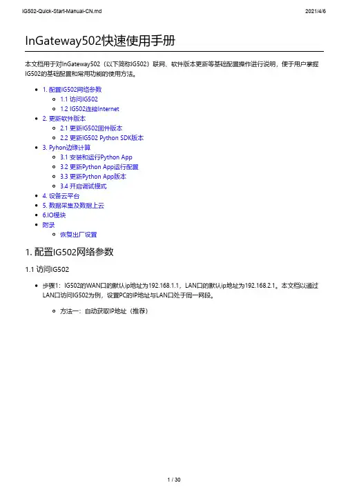
InGateway502快速使用手册本文档用于对InGateway502(以下简称IG502)联网、软件版本更新等基础配置操作进行说明,便于用户掌握IG502的基础配置和常用功能的使用方法。
1. 配置IG502网络参数1.1 访问IG5021.2 IG502连接Internet2. 更新软件版本2.1 更新IG502固件版本2.2 更新IG502 Python SDK版本3. Pyhon边缘计算3.1 安装和运行Python App3.2 更新Python App运行配置3.3 更新Python App版本3.4 开启调试模式4. 设备云平台5. 数据采集及数据上云6.IO模块附录恢复出厂设置1. 配置IG502网络参数1.1 访问IG502步骤1:IG502的WAN口的默认ip地址为192.168.1.1,LAN口的默认ip地址为192.168.2.1。
本文档以通过LAN口访问IG502为例,设置PC的IP地址与LAN口处于同一网段。
方法一:自动获取IP地址(推荐)方法二:使用固定IP地址选择“使用下面的IP地址”,输入IP地址(默认为192.168.2.2~192.168.2.254中任意值);子网掩码(默认255.255.255.0);默认网关(默认为192.168.2.1)以及DNS服务器地址,单击确定。
步骤2:打开浏览器,访问IG502的LAN口IP地址并输入登录用户名和密码。
设备出厂的用户名/密码默认为adm/123456。
步骤3:登录成功后,您可以看到如下图所示的网页。
名和密码。
步骤5:如需修改LAN口的IP地址可访问IG502的“网络>>网络接口>>LAN”页面进行修改。
1.2 IG502连接Internet方法一:使用SIM卡拨号连接Internet步骤1:将SIM卡插入卡槽(注意:插拔SIM卡操作时,必须拔掉电源,以免造成数据丢失或设备损坏)。
插入SIM卡后将4G LTE天线与ANT口连接,接通IG502的电源。
智能扫地机语音方案、智能吸尘器GBD502-16P语音模块一、语音模块产品特征:(模块型号:GBD502-16P)1、支持PCM、ADPCM WAV音频格式播放,音质优美;2、语音制作非常方便,用户可以直接通过上位机,可将mp3、wmv等格式自动转换得到;3、支持外挂最大64M SPI Flash作为存储语音的载体,语音长度可达2000多秒;4、最多可支持3328段语音;5、通过usb用上位机直接更新语音数据;6、支持四种控制模式:标准模式,按键模式一线串口模式,三线串口模式;7、支持播放背景音乐、广告语;8、支持插播功能,插播后能耐从前次播放的语音断点处继续播放;9、支持进行任意段语音的播放;10、支持混音功能;11、支持最大64M SPI-FLASH;12、工作电压DC2.8~3.6V。
13、应用范围本产品稳定性好,音质出色,适合应用在汽车电子,高级玩具,游戏机,家用电器,安防系统,喊话器等场合。
14、控制模式GBD502-S具有按键控制模式,一线串口控制模式,三线串口控制模式。
二、语音芯片特征(芯片型号:GBD502-SOP16)◆ OTP 一次性语音芯片。
◆ 6KHz 单声道采样时,最大时长 20s 语音。
◆宽工作电压范围 2.5V~4.5V。
◆支持 DAC 输出以及 PWM 输出两种方式。
◆内置功放输出,可直接驱动 0.5W 喇叭。
◆最多支持 4 通道的和弦音乐(MIDI)播放。
◆内嵌高速 DSP 处理器内核处理器,具有强大的可编程能力。
◆内置 16-bit DA 转换器,内置 PSG 语音合成器,音质高,优于市面上传统的语音芯片。
◆休眠任意控制,休眠静态电流功耗低于 2uA。
◆四种封装形式:DIP16 、SOP16 、SOP20 ,TSOP16。
◆可通过专业的上位机软件轻松组合语音,可任意插入静音,且不占用语音空间,相同的语音可重复调用。
◆可任意设定语音播放忙信号 BUSY 的输出方式。

READ ME FIRST QUICK INSTALL GUIDE52-Port Stackable Gigabit PoE+L2/L3 Managed SwitchXMS-7048PIncludes:XMS-7048P 52-Port PoE SwitchPower CordMounting HardwareINSTALLATION AND SETUP1Physical InstallationThe XMS-7048P can easily be installed in a standard 19” rack. Two mounting ears are included for installing and stabilizing the switch. When attaching the mounting ears and installing the switch in a rack, please refer to the following illustration:Rack-Mounting the XMS-7048PU sing the included screws, attach the mounting ears to each sideof the switch.M ount the switch in the rack with the LEDs facing outwards. Be sure the switch is level and properly secured in the rack.Desktop SetupFor use as a desktop device, position and apply the included rubber feet to the bottom of the XMS-7048P.2Connecting Ethernet and PowerEthernet and Power ConnectionsUse one of the 50 Ethernet ports to connect the XMS-7048P to any Ethernet-enabled device, including servers, routers or other switches.No crossover cable is necessary.3 Preparing for AccessIP AddressingIf the XMS-7048P is connected to a network with a 192.168.0.X address scheme, and your computer shares a similar address on the same network, you can skip to the next step, Access and Setup.n Note:I f another device on your network shares the 192.168.0.4 address, you’ll need to temporarily reassign or remove thatdevice while you configure the XMS-7048P.If your network uses an address scheme other than 192.168.0.X, you’ll need to set a temporary static IP address on the computer you’re using for configuration. To do so, set the IP address of your computer to an address in the 192.168.0.X range, then set the Gateway/Router address to 192.168.0.4 (the default IP address of the XMS-7048P).Once you’re finished configuring the switch, you can return your comput-er’s IP configuration to normal, typically “Obtain Automatically/DHCP.”n Note:V isit /ip-addressing to learn more about changing your computer’s IP address and getting connected.4Access and SetupGetting ConnectedUse an Ethernet cable to connect your computer to the XMS-7048P, then power on the switch.Logging InTo access the XMS-7048P web configuration, open your web browser and enter the switch’s default 192.168.0.4 IP address in the address field. Log in to the switch using the default user name and password:Default IP: 192.168.0.4Username: adminPassword: adminSelect the menu items on the left to view and/or modify the configuration. Refer to the Quick Setup Guide at for more detailed information on setup, IP configuration and routing, PoE, VLANs, Spanning Tree, and Stacking.5Hardware OperationFront PanelThe front panel of the XMS-7048P includes 50 Gigabit Ethernet RJ-45 ports, two 10-Gigabit SFP+ ports, status-, link- and PoE LEDs, a Mode/Reset button and an RJ-45 Console port.XMS-7048P Front Panel ViewRear PanelThe Rear Panel of the XMS-7048P features a standard AC power input and a redundant power supply (RPS) connector for use with an external power supply.LED IndicatorsThe LED indicators on the XMS-7048P include System, Link/Act and PoE LEDs, and an LED for each port. These LED indicators show the operating status of the XMS-7048P and each port connection.Mode/Reset Button to Change LED FunctionalityTapping the Mode/Reset button briefly switches the port indicator between displaying port link speed and PoE status.The following chart shows the LED indicators of the XMS-7048P along with anexplanation of the indicator’s properties:Mode/Reset Button to Reset/RestoreThe Reset button (located at the lower-left corner of the front panel) is used to reset (reboot) the switch, or to restore the switch to factory default settings.X To Reboot/Reset the Switch: With the XMS-7048P powered on, press the Reset button for approximately three seconds until the Link/Act and PoE LEDs both light, then release the button.c CAUTION:D o not hold the button for more than four seconds.Doing so could erase all settings and restorefactory defaults.X To Restore Default Settings: With the XMS-7048P powered on, press and hold the Reset button approximately eight seconds, until both the Link/Act and PoE LEDs turn off, then release the Reset button and the switch automatically restores factory default settings and reboots. Once the System LED starts flashing again, the XMS-7048P is running with factory defaults.c CAUTION:P lease note that restoring Default Settings will removeany/all custom configuration.Sales P: 801-822-5450 E:***************Technical SupportP: 801-822-5450 Option 3 E:*****************LUX-QIG-XMS-7048P-v3 01251710Copyright and Trademark Noticestrademarks and registered trademarks are property of their respective holders.。

I N S T A L L A T I O N I N S T R U C T I O NSFCA501 / 502 / 503FCA501 / 502 / 503Installation Instructions2DISCLAIMERMilestone AV Technologies and its affiliated corporations and subsidiaries (collectively "Milestone"), intend to make thismanual accurate and complete. However, Milestone makes no claim that the information contained herein covers all details,conditions or variations, nor does it provide for every possible contingency in connection with the installation or use of this product. The information contained in this document is subject to change without notice or obligation of any kind. Milestone makes no representation of warranty, expressed or implied,regarding the information contained herein. Milestone assumes no responsibility for accuracy, completeness or sufficiency of the information contained in this document.Chief® is a registered trademark of Milestone AV Technologies.All rights reserved.IMPORTANT SAFETY INSTRUCTIONSWARNING: A WARNING alerts you to the possibility ofserious injury or death if you do not follow the instructions.CAUTION: A CAUTION alerts you to the possibility ofdamage or destruction of equipment if you do not follow the corresponding instructions.WARNING:Failure to read, thoroughly understand, andfollow all instructions can result in serious personal injury,damage to equipment, or voiding of factory warranty! It is the installer’s responsibility to make sure all components are properly assembled and installed using the instructions provided.WARNING:Exceeding the weight capacity can result inserious personal injury or damage to equipment! It is the installer’s responsibility to make sure the combined weight of all components placed on the FCA501/FCA502/FCA503 does not exceed 10 lbs (4.5 kg).WARNING:Use this mounting system only for its intendeduse as described in these instructions. Do not use attachments not recommended by the manufacturer.WARNING:Never operate this mounting system if it isdamaged. Return the mounting system to a service center for examination and repair.WARNING:Do not use this product outdoors.WARNING:RISK OF INJURY TO PERSONS! Do not usethis mounting system to support video equipment such as televisions or computer monitors.--SAVE THESE INSTRUCTIONS--DIMENSIONSInstallation Instructions FCA501 / 502 / 503 DIMENSIONS - continued3FCA501 / 502 / 503Installation Instructions4LEGENDTOOLS REQUIRED FOR INSTALLATIONPARTSApretar elemento de fijación Befestigungsteil festziehen Apertar fixador Serrare il fissaggio Bevestiging vastdraaien Serrez les fixations Aflojar elemento de fijación Befestigungsteil lösen Desapertar fixador Allentare il fissaggio Bevestiging losdraaien Desserrez les fixationsDestornillador Phillips Kreuzschlitzschraubendreher Chave de fendas Phillips Cacciavite a stella Kruiskopschroevendraaier Tournevis à pointe cruciforme Llave de boca Gabelschlüssel Chave de bocas Chiave a punte aperte Steeksleutel Clé à fourche#23/8"Figure 25FCA501 / 502 / 503Installation Instructions6Figure 4Installing ComponentsWARNING:Exceeding the weight capacity can result inserious personal injury or damage to equipment! It is the installer’s responsibility to make sure the combined weight of all components located on the FCA501/FCA502/FCA503does not exceed 10 lbs (4.5 kg).NOTE:OPTIONAL : Slots are provided in shelf for strap (notincluded) to hold component in place. (See Figure 5)Installing Camera1.Install 1/4-20 x 3/8" Phillips pan machine screw (E) through mounting slot on shelf and into hole on bottom of camera (not included). (See Figure 5)2.Route cable from camera towards back of shelf and down behind the FCA501/502/503. (See Figure 5)Installation Instructions FCA501 / 502 / 5037FCA501 / 502 / 503Installation InstructionsUSA/InternationalA 6436 City West Parkway, Eden Prairie, MN 55344P 800.582.6480 / 952.225.6000F 877.894.6918 / 952.894.6918EuropeA Franklinstraat 14, 6003 DK Weert, Netherlands P +31 (0) 495 580 852F +31 (0) 495 580 845Asia PacificAOffice No. 1 on 12/F, Shatin Galleria 18-24 Shan Mei Street Fotan, Shatin, Hong Kong P 852 2145 4099F 852 2145 4477Chief Manufacturing, a products division of Milestone AV Technologies 8800-002260 Rev002012 Milestone AV Technologies, a Duchossois Group Company 11/12。
FLASHWAVE® 4020Ethernet Service PlatformThe FLASHWAVE® 4020 Ethernet ServicePlatform (ESP) cost-effectively delivers revenue-generating services1Ethernet and DS1 services at the lowest possible costThe FLASHWAVE® 4020 Ethernet Service Platform (ESP) cost-effectively delivers revenue-generating services. This platform supports both DS1 and Ethernet services over protected or unprotected OC-3 or OC-12 network interfaces, offering you the ability to deliver simultaneous data and voice services to customer premises. This capability makes the FLASHWAVE 4020 ESP an ideal solution for business access applications.The FLASHWAVE 4020 ESP has two fixed optics configurations and two flexible Small Form-factor Pluggable (SFP) configurations. Two FLASHWAVE 4020 base units without OC-3 or OC-12 optics have been created for SFP support. Fujitsu has qualified IR, LR and Coarse WDM (CWDM) SFP modules, usable with these base units. Carriers can combine an OC-3 or OC-12 base unit with any two matching-rate SFP modules to create a custom FLASHWAVE 4020 shelf. Each configuration offers easy deployment, while supporting an advanced set of DS1 and Ethernet over SONET (EoS) transport capabilities. The platform supports seven DS1 ports and four 10/100Base-T Ethernet ports over dual OC-3 or dual OC-12 network interfaces. The dual optical interfaces allow the FLASHWAVE 4020 ESP to be configured for 1+1 protected, Unidirectional Path Switched Ring (UPSR) or unprotected network applications. This versatile platform features:• A single Network Element (NE) for both DS1 and Ethernet services, reducing equipment and operational costs• S implified planning, ordering, training, installation and troubleshooting due to the elimination of service-specific plug-in modules Simple installation and maintenanceThe FLASHWAVE 4020 ESP is easy to install and features:• A set of 19 and 23” rack or wall-mounting brackets for a secure cabinet• S upport for dual –48 V DC or AC power feeds with optional AC adapter module• Quick installation and turn upCarrier-class reliability and featuresThe FLASHWAVE 4020 ESP is a powerful, standards-based SONET Multiservice Provisioning Platform (MSPP) that can be deployed in an access network along with other SONET NEs. Specific features include:• D ual OC-3 or OC-12 optical interfaces that are configurable for UPSR, 1+1 Automatic Protection Switching (APS), or unprotected operation • IR and LR SFP modules for improved networking flexibility• I TU-T compliant CWDM SFP modules providing up to an eight-fold increase in usable fiber bandwidth• Sub-50 ms SONET protection switching• H igh- and low-order Virtual Concatenation (VCAT) with support for Link Capacity Adjustment Scheme (LCAS) allowing Ethernet services to temporarily remove defective paths and continue transmission over working paths• S upport for any mix of VT1.5, STS-1 and STS-3 paths on the SONET interfaces with non-blocking cross connections between any path and an Ethernet or DS1 port or another path• E xtensive Operation, Administration, Maintenance and Provisioning (OAM&P) capabilities with full Performance Monitoring (PM) support and loopback capabilities• A bility to derive synchronization timing from the OC-3/OC-12 line interfaces or internal Stratum 3 clock• N ETSMART® 500 Element Management System (EMS), NETSMART 1500 Network Management System (NMS) support and an integrated Simple Network Management Protocol (SNMP) agent Standards compliance and interoperabilityThe FLASHWAVE 4020 ESP complies with all applicable Telcordia®, ITU, IEEE and ANSI standards, allowing the NE to interoperate with other standards-based NEs, including the entire Fujitsu FLASHWAVE 4000 series of MSPPs. The FLASHWAVE 4020 ESP uses ITU-T standard procedures for encapsulation and framing, VCAT and LCAS to enable multivendor interoperability.FLASHWAVE® 4020 Ethernet Service Platform2FLASHWAVE® 4020Ethernet Service PlatformArchitectures• Terminal• Linear ADM (1+1)• Unidirectional Path Switched Ring (UPSR)Configurations• O C-3 base unit, seven DS1 and four 10/100Base-TEthernet services, with integrated OC-3 line optics• O C-12 base unit, seven DS1 and four 10/100Base-TEthernet services, with integrated OC-12 line optics• O C-3 Base Unit, seven DS1 and four 10/100Base-TEthernet, without SFP modules• O C-12 Base Unit, seven DS1 and four 10/100Base-TEthernet, without SFP modulesInterfaces DS1RJ-48c connectorsEthernet RJ-45 connectorsOC-3L C connectors1310 nm single-mode/multimodeOC-12L C connectors1310 nm single-mode/multimodeOC-3 SFP modules L C connectors1310 nm IR, 1310 nm LR1, 1550 nm LR2, and eight CWDM (1471 to 1611 nm with 20 nm spacing)OC-12 SFP modules L C connectors1310 nm IR, 1310 nm LR1,1550 nm LR2, and eight CWDM (1471 to 1611 nm with 20 nm spacing)Ethernet capabilities Mapping• V T1.5, VT1.5-xv (x = 1 to 64)• STS1, STS1-nv (n = 1 to 3)• STS3cLCAS addition/removal of VT/STS pathsGFP and PPP encapsulationAuto-negotiationTransports Ethernet frames up to 9600 bytes Protection DS1unprotectedEthernet unprotectedOC-31+1, UPSR or unprotected (0:1, 0:2)OC-121+1, UPSR or unprotected (0:1, 0:2)Synchronization• Internal Stratum 3 clock• Synchronization Status Messaging (SSM)• OC-3 line timing• OC-12 line timingOperations• TL1 protocol over OSI/SDCC and IP/LCN• Optional TL1 protocol over IP/SDCC• S NMP protocol over OSI/SDCC tunnel or IP/LCN (foralarms and PM)• Optional SNMP protocol over IP/SDCC• RS-232 craft interface• S oftware download and remote memorybackup/restore• NETSMART® 500 EMSsupport• NETSMART 1500 NMS support• Interoperable with all Fujitsu transmission products• Telcordia™ TIRKS®, NMA® and Transport support• MEF9 certified• Four housekeeping inputs• SFP management for SFP-capable configurations Power consumption/heat dissipationPowerconsumption43.5 WHeatdissipation164 BTU/hrOperatingenvironmentTemperature0 to 50° C (32 to 122° F)Humidity 5 to 95% (non-condensing)NEBS Level 3UL compliantPhysicalcharacteristicsDimensions(H x W x D)1.75 x 17.5 x 9”Weight 4.8 lb (2.2 kg)Power input D ual –48 V DC(optional AC/DC power converter)Mountingoptions19 or 23” rack mountOptiFeatures and specificationsFujitsu Network Communications Inc. 2801 Telecom Parkway, Richardson, TX 75082 Tel: 800.777.FAST (3278) Fax: 972.479.6900 /telecom© Copyright 2011 Fujitsu Network Communications Inc. FLASHWAVE® and NETSMART® are trademarks of Fujitsu Network Communications Inc. (USA). FUJITSU (and design)® and “shaping tomorrow with you” are trademarks of Fujitsu Limited.All Rights Reserved. All other trademarks are the property of their respective owners.Configuration requirements for certain uses are described in the product documentation. Features and specifications subject to change without notice.4.0/R1.1.2/07.093。
151413121110986543211617199WIRE ROPE END FITTINGSCopyright © 2023 The Crosby Group LLC All Rights Reserved• Forged from special bar quality carbon steel, suitable for cold forming.• Swage socket terminations have an efficiency rating of 100% based on the catalog strength of wire rope.• Hardness controlled by spheroidize annealing.• Stamp for identification after swaging without concern for fractures (as per directions in Wire Rope End Terminations User’s Manual).• Swage sockets incorporate a reduced machined area of the shank which is equivalent to the proper 'after swage' dimension. Before swaging, this provides for an obvious visual difference in the shank diameter. Afterswaging, a uniform shank diameter is created allowing for a QUIC-CHECK ® and permanent visual inspection opportunity.• S-502 Swage Sockets are recommended for use with 6 x 19 or 6 x 37, IPS or XIP (EIP), XXIP (EEIP), RRL, FC or IWRC wire rope.• In accordance with ASME B30.9, all slings terminated with swage sockets shall be proof loaded.*NOTE: Before using any Crosby fitting with any other type lay, construction or grade of wire rope, it is recommended that the termination be destructive tested and documented to prove the adequacy of the assembly to be manufactured.8 strand 2160 Grade pendants. Note: Fittings designed only to be used on exact sizes listed.S-502。
无锡蓝天防火门模块502说明书1. 产品介绍无锡蓝天防火门模块502是一种高性能的防火门,主要用于建筑物中的防火分区。
该产品采用优质钢材制作,具有良好的耐火性能和结构强度,能有效地隔离火灾蔓延,保护人员和财产安全。
2. 产品特点•耐火性能优异:无锡蓝天防火门模块502采用特殊的耐高温材料,经过严格测试,具有良好的耐火性能,在高温环境下仍然能保持稳定的结构。
•结构强度高:该产品采用钢材制作,具有较高的结构强度,能够承受一定程度的外力冲击和压力变化。
•易于安装:无锡蓝天防火门模块502采用模块化设计,安装方便快捷。
同时提供详细的安装说明书和视频教程,使安装过程更加简单明了。
•美观大方:该产品外观设计简洁大方,可根据客户需求进行个性化定制,满足不同建筑风格的需求。
3. 技术参数•耐火等级:A级、B级、C级•防火时间:30分钟、60分钟、90分钟•尺寸:标准尺寸为2100mm×900mm×50mm,可根据客户要求进行定制•材质:优质钢材•表面处理:防火漆喷涂4. 安装步骤1.准备工作:确认门洞尺寸是否与产品尺寸相符,清理门洞内的杂物和灰尘。
2.安装门扇:将防火门扇放入门洞中,并使用水平仪进行调整,确保门扇垂直水平。
3.安装门框:将防火门框与墙体固定连接,并使用水平仪进行调整,确保门框垂直水平。
4.安装密封条:将密封条安装在防火门框和门扇之间,确保密闭性能。
5.检查功能性能:确认防火门开启、关闭是否灵活顺畅,并检查锁具、闭锁器等功能部件是否正常运行。
6.进行验收测试:按照相关标准进行防火门的验收测试,确保产品性能符合要求。
5. 维护与保养•定期清洁:使用干净的软布擦拭防火门表面,避免使用有腐蚀性的清洁剂。
•定期涂漆:根据需要,定期对防火门进行涂漆维护,以保持其外观和耐火性能。
•定期检查:每年至少进行一次全面检查,包括门扇、门框、密封条等部件的磨损情况和功能性能。
6. 注意事项•在安装过程中,请确保操作人员具有相关经验和技能,并严格按照安装说明书进行操作。
精心整理组态王与单片机协议1.通讯口设置:通讯方式:RS-232RS-485RS-422均可。
波特率:由单片机决定注意:在组态王中设置的通讯参数如波特率,数据位,停止位,奇偶校验必须与单片机编程中的通讯参数一致2.在组态王中定义设备地址的格式格式:##・#前面的两个字符是设备地址,范围为0—255,此地址为单片机的地址,由单片机中的程序决定;后面的一个字符是用户设定是否打包,“0”为不打包、“1”为打包,用户一旦在定义设备时确定了打包,组态王将处理读下位机变量时数据打包的工作。
3.在组态王中定义的寄存器格式斜体字dd代表数据地址,此地址与单片机的数据地址相对应。
注意:在组态王中定义变量时,一个X寄存器根据所选数据类型(BYTE,UINT,FLOAT)的不同分别占用一个、两个,四个字节,定义不同的数据类型要注意寄存器后面的地址,同一数据区内不可交叉定义不同数据类型的变量。
为提高通讯速度建议用户使用连续的数据区。
例如,1、在单片机中定义从地址0开始的数据类型为BYTE型的变量:则在组态王中定义相应的变量的寄存器为X0、XI、X2、X3>X4oooooooo,数据类型为BYTE,每个变量占一个字节2、在单片机中定义从地址100开始的数据类型为UINT型的变量:则在组态王中定义相应的变量的寄存器为X100、X102、X104、X106、X108。
,数据类型UINT,每个变量占两个字节3、在单片机中定义从地址200开始的数据类型为FLOAT型的变量:则在组态王中定义相应的变量的寄存器为X200、X204、X208、X212。
,数据类型FLOAT,每个变量占四个字节3.组态王与单片机通讯的命令格式:读写格式(除字头、字尾外所有字节均为ASCII码)说明;字头:1字节1个ASCII码,40H设备地址:1字节2个ASCII码,0—255(即0—OxOffH)标志:1字节2个ASCII码,bit0~bit7, bitO=O:读,bitO=l:写。
安全技术说明书页: 1/11 巴斯夫安全技术说明书按照GB/T 16483编制日期 / 本次修订: 30.05.2023版本: 8.0日期/上次修订: 16.03.2022上次版本: 7.2日期 / 首次编制: 11.01.2007产品: 安固力 ECO 502 apProduct: Acronal® ECO 502 ap(30397973/SDS_GEN_CN/ZH)印刷日期 03.09.20231. 化学品及企业标识安固力 ECO 502 apAcronal® ECO 502 ap推荐用途: 原料, 仅用于工业用途公司:巴斯夫(中国)有限公司中国上海浦东江心沙路300号邮政编码 200137电话: +86 21 20391000传真号: +86 21 20394800E-mail地址: **********************紧急联络信息:巴斯夫紧急热线中心(中国)+86 21 5861-1199巴斯夫紧急热线中心(国际):电话: +49 180 2273-112Company:BASF (China) Co., Ltd.300 Jiang Xin Sha RoadPu Dong Shanghai 200137, CHINA Telephone: +86 21 20391000Telefax number: +86 21 20394800E-mail address: ********************** Emergency information:Emergency Call Center (China):+86 21 5861-1199International emergency number: Telephone: +49 180 2273-1122. 危险性概述纯物质和混合物的分类:严重损伤/刺激眼睛: 分类2A对水环境的急性危害: 分类3巴斯夫安全技术说明书日期 / 本次修订: 30.05.2023版本: 8.0产品: 安固力 ECO 502 apProduct: Acronal® ECO 502 ap(30397973/SDS_GEN_CN/ZH)印刷日期 03.09.2023 标签要素和警示性说明:图形符号:警示词:警告危险性说明:H319造成严重眼刺激。
FLA-502汽车排气分析仪使用说明书Va.3粤制06000117号-1广州市福立分析仪器有限公司广州市福立分析仪器有限公司佛山分公司■目录前言 (3)质量保证承若及责任 (3)名称与功能 (5)●前视图 (5)●后视图 (5)测量前准备 (6)●连接取样元件和排气管 (6)●检查过滤元件 (6)●检查保险丝 (7)●检查电源 (7)●气管连接 (7)日常操作与测量 (8)日常操作 (8)●动作检查 (8)●泄漏检查 (9)●H C吸附测试 (10)●时钟设置 (11)●符号选择 (11)●通讯设置 (11)●燃料H/C设置 (12)●转速信息设置 (12)●校准 (13)●零气选择 (13)●标定 (14)测量 (16)状态检查 (17)简易诊断 (18)维修注意事项 (19)元件更换 (19)●过滤元件的更换 (19)●传感器的更换 (19)保养检查 (21)技术参数 (22)输出信号说明 (24)■前言本公司生产的FLA-502汽车排气分析仪采用具有国际水平的进口红外检测器,该仪器能同时测定汽车排气中的HC、CO、CO2、或/和O2、NO四组份或五组份之浓度值,还可以测试汽车发动机转速、空燃比及机油温度,环境温度与湿度、大气压力。
FLA-502采用大屏幕液晶显示,全中文提示,多燃料测试,有多种测量模式,包括双怠速测试。
其中:HC、CO、CO2组份检测采用不分光红外检测器,NO组份检测可采用不分光红外检测器(使用寿命长,响应速度快)或电化学传感器(NO检测器根据用户需要选择安装),O2采用电化学传感器。
为了能正确使用仪器,在使用之前请仔细阅读本使用说明书,并请妥善保管,以备需要时查阅。
■质量保证承诺及责任您所购买的FLA-502汽车排气分析仪享有广州市福立分析仪器有限公司提供的一年保修期。
在此期间,仪器如有任何属于本公司责任的故障,我们将会为您免费维修或更换零件。
此保修范围不包括以下几点:由于使用不当而无法正常工作的;由于不是本公司授权的任何单位或个人所修理过或改变过而不能正常工作的;由于在不适宜的工作环境下使用而引起不能正常工作;由于意外事故而引起的不能正常工作;由于跌落而造成的不能正常工作;广州市福立分析仪器有限公司任何时候都保留有对该产品及其设计或本使用说明书进行更改的权利,如有更改,恕不另行通知。
注意:由于用户不按本手册规定的操作方法和工作环境使用仪器而造成的损坏或故障,或者您未能遵守我们在手册中列出的注意、警告等事项而造成的经济损失或仪器损坏,本公司将不承担任何责任。
■安全注意事项在进行测试之前阅读本使用说明书。
本仪器使用的电源电压为AC 220V 50Hz 60VA。
仪器必须与接地电源连接,避免触电,在打开电源之前,应确保电源电压是正常的。
不要擅自打开或拆卸仪器。
不能将仪器放在汽车挡泥板或其它有振动的地方,以免仪器掉落下来。
切不可让水、灰尘或其他非气态物质进入仪器,否则过滤器将堵塞并污染仪器内部器件而导致不能正常测量。
在通风良好的地方操作仪器,用一条内径16mm、长约3~5m(具体长度视仪器摆放位置到通风窗口而定)的聚氯乙烯管接到仪器后面板上的排气口,将仪器排出的废气引到室外安全的地方。
以防止操作者吸入一氧化碳而发生中毒事故。
不要在温度过高、过低或温度变化剧烈的环境中使用仪器。
不要将仪器直接暴露在太阳下。
仪器工作的环境温度为0℃~40℃。
取样探头、测试装置及导线、手、衣服、头发和其它物体必须避开汽车的运动部分,如风扇叶片、传送链等。
测量油温、转速时,传感器的引线切勿与汽车的高温部位接触,以防导线受热熔化。
■顾客服务如果您需要操作及技术问题方面的帮助,请与我公司联系。
我们很乐意给您提供帮助。
我们的联系电话:①广州市(020)81501590 81615299;②佛山市(0757)- 88357166(售后服务专线)、82106910;传真:①广州市(020)81615299 ②佛山市(0757)-82106910。
■维修注意事项如果分析仪需要维修,请与制造厂或销售商联系。
如果需运回分析仪,请用原先的包装箱把它包装好。
我们建议您给装货保险。
为了帮助您得到有效的服务,请遵循以下规则:1.按照手册上的所有说明,确认是分析仪的问题,而不是其它设备、试样纯度或导线连接的问题。
2.如果您确定需要维修,请与厂方联系,而且在送还分析仪维修之前确保已包含以下材料:•精确的试样及操作环境的说明;•故障的简单说明;•仪器的编号;•您的名字、地址及电话号码。
■用户不遵守有关之使用说明,后果自负。
倘若用户不遵守本说明书中所述之注意事项、警告或其他类似之说明,广州市福立分析仪器有限公司概不负责由此而引起的损失和/或损坏。
本产品执行标准:标准号Q/(GZ) FLFX 2—2008简易工况汽车排气分析仪■名称与功能◆前面板视图◆后面板视图注:“样气过滤器”作用是除去样气中的杂质。
■测量前准备◆检查过滤元件1、检查各过滤器滤芯是否清洁。
2、检查各过滤器密封圈放置位置是否正确。
主机后面板微孔滤芯锁紧螺母上出气咀上过滤芯柱下过滤芯柱过滤器密封圈样气过滤器座气咀(样气入口)微孔滤芯滤芯压盖锁紧螺钉滤芯压盖过滤器透明外罩3、检查过滤器透明外罩是否已旋紧。
◆检查保险丝拔下连接仪器端电源线插头,用大拇子往右按的同时往前拉保险丝外壳,露出保险丝,取出并检查,其标值应为2A。
◆检查电源电源线应接在仪器所标明的电压和频率的电源上,请不要将仪器放置在电焊机等产生显著干扰的场所附近,以及不要与这类装置共用一个电源,电源座应有接地端子。
◆气管连接1、将一条内径为16mm的乙烯管连接在仪器排气口处,把废气排放到室外。
2、将一条内径为6mm,长约5米的PU管子,一端接仪器“压缩空气”气咀,另一端接“空气过滤、调压阀”气咀(本仪器附件盒内配套了一只),“空气过滤、调压阀”的另一端气咀通过连接管与压缩机输出端连接。
◆其他1、配备一瓶用于排气仪零点及氧传感器标定的标准气体:气体纯度要求:O2 = 20.9%HC < 1×10⁻⁶CO < 1×10⁻⁶CO2 < 200×10-6NO < 1×10⁻⁶平衡气体为N2,纯度=99.99%。
2、配备两瓶用于标定与检查排气仪CO、CO2、HC及NO组分的标准气体:低量程标气(检查用气)高量程标气(标定用气)气体成分浓度气体成分浓度C3H8约200×10-6 (丙烷)C3H8约3200×10-6 (丙烷)CO 约 0.5×10⁻²CO 约 8.0×10⁻²CO2约 6.0×10⁻²CO2约 12×10-2NO 约 300×10-6NO 约 3000×10-6平衡气体N2纯度=99.99%平衡气体N2纯度=99.99%仪器的操作■日常操作与测量◆日常操作预热1、打开电源开关(如图1);2、仪器完成预热、调零动作后进入“准备”状态(如图2)。
图1注:每天首次开启仪器,电化学NO传感器自检15秒后即进入进入【准备】状态;红外NO传感器自检15秒后进入预热倒计时状态,15分钟后完成预热。
图2动作检查为了检查仪器外部各管路连接正确与否,依照图2界面提示按“↓”按键,进入“动作检查”界面(图3)后开始作如下操作:1、在图1界面中按“↓”键,进入如图3界面;2、按“→”键可选择任一功能项,按一次“确定”键后即产生相应动作,再按一次“确定”键即停止动作。
3、按“↓”键可看到各功能键动作时的状况。
返回如图2界面。
4、检查完毕在上述第3步状态下按“功能”键仪器自动调零后返回如图2界面。
图3正确动作判别提示:检查项目图示说明压缩空气LV1 ◎压缩空气LV1 ◎通零气LV2 ◎测量阀DV2◎检测阀DV1选择纯氧气作零气,需分别在压缩气咀接入压缩空气,在零气咀入口接入氧气。
◎压缩空气LV1 ◎测量阀DV2 ◎抽样气PUMP 选择空气作零气,抽气泵动作。
通零气LV2◎通零气LV2 ◎检漏阀DV1 选择纯氧气作零气◎通零气LV2 ◎检漏阀DV2 ◎抽样气PUMP 选择空气作零气,抽气泵动作。
通标准气LV3 ◎通标准气LV3 ◎检漏阀DV1通检查气LV4 ◎通检查气LV4 ◎检漏阀DV1测量阀DV2 ◎测量阀DV 2检漏阀DV1 ◎检漏阀DV1抽样气PUMP ◎抽样气PUMP 抽气泵、排水泵动作抽环境气◎抽环境气◎测量阀DV 2 ◎抽样气PUMP 抽气泵动作泄漏检查为了保证测量时仪器没有泄漏,确保测量结果的准确,当仪器进入准备状态,按屏幕提示:1、在“准备”界面,按“功能”键进入“菜单”界面(如图4);2、按“→”键把光标移到【泄漏测试】,然后按“确认”键;3、依照显示屏提示用“泄漏检查密封帽”堵住探头的入口或过滤器弯头组件气咀(见第4页“后示图”所示位置),按“确定”键启动泄漏测试程序(如图5)。
如果不想进行泄漏测试,按“功能”键返回“菜单”选择其它项目。
图4注意:根据液晶显示屏的液晶材料的物理特性,液晶的亮度对比度会随着气温的改变而产生相应变化。
气温越低出现“白屏”的机会越大,此时需要通过按仪器前面板的亮度调节按键来改变液晶显示屏的亮度对比度。
图5泄漏检查流程:测试中。
检查流量通路 检查有无泄漏。
不合格合格 有泄漏,请检查气路后,按“结果确定”键重测。
检查气路后,按按“功能”键 无泄漏,仪器屏幕显示合格。
“确定”键重测返回菜单 按“功能”键返回选择“菜单”,(如图4)进入下一项检查选择。
HC吸附测试当发现HC测量值偏差较大时,就要进行HC吸附检查。
一般可分两步检测确认:㈠断开取样管和取样探头后检查,若检测不合格,就要开抽气泵或输入零气吹洗,经过吹洗仍然不合格就要更换仪器内部气路和清洗检测器气室;㈡接上取样管和取样探头后检查,若检测不合格,可通过压缩空气吹洗,吹洗后仍然不合格就要更换取样管。
下面介绍断开取样管和取样探头后检查的【HC吸附测试】操作方法:按显示屏幕提示,从取样管中取出探头(如图6):1、分别按“→”键、“↓”键把光标移到【HC吸附测试】(如图4);2、按“确定”键开始吸附检查。
如果不想进行“HC吸附测试”,按“功能”键返回“菜单”界面。
图6HC吸附测试流程:按“确定”键 测试结束,显示合格或不合格信息。
泵抽气30秒钟 HC 12ppm(或×10-6)vol 不合格。
HC<12ppm (或×10-6)vol合格。
不合格合格结果重复检测仍不合格,应吹洗气路后,再重做【HC吸附测试】。
按“确认”键按“功能”重复检测键返回菜单时钟设置1、按“↓”键或“→”键把光标移到【时钟设置】(如图4);2、按“确定”键进入时钟设置选择界面(如图7);3、按“↓”键移动光标,按“→”修改数字;4、按“确定”键执行修改并退出。