AOZ1014手册
- 格式:pdf
- 大小:1.12 MB
- 文档页数:21

cascadeாFor Technical Assistance call: 800-227-2233, Fax: 888-329-8207Serial NumberModelc Parts ManualVisionary Multi Load Handler55E-FD-32955EREF QTY PART NO.DESCRIPTION16665595No Hand Hold Decal 24679150No Step Decal11222SD0106.illOn upper hooks12PublicationsDecals55EPART NO.DESCRIPTIONParts Manual 213580Operator’s Guide213372Installation Instructions 679929Tool Catalog673964Literature Index Order FormTO O L C A T A L O GPA R T S MA N UA LSE RV I C EM AN U AL GA0006.epsIN S TA L L A T I O N IN S TR cascade Service Literature Index and Order Formcascade PERATOR’S GUIDEOCommon PartsREF QTY PART NO.DESCRIPTION72210489Rod End Anchor s84768303Capscrew, M10 x 35 s94210140Bearing Retainer1010787375Capscrew, M8 x 20 GR 8.8 111214631T-Bar – Lower121211380Retainer/Stop – RH131211379Retainer/Stop – LH1444730-1050Bearing Segment1550211689Capscrew, M12 x 30 GR 10.9 161214635T-Bar – Upper171216838Valve Assembly v181211456Manifold196768208Capscrew, M8 x 25204768795Capscrew, M8 x 30211675548Sideshift Cylinder q 222672018Upper Bearing232208350Lower Bearing5See Frame Cylinder page for parts breakdown.v See Valve Assembly – Class III page for parts breakdown. s Included in Cylinder Rod Anchor Kit 213856.REF QTY PART NO.DESCRIPTION241212740Spacer Block252767615Capscrew, M10 x 25262209741Rod End s274684649Capscrew, M10 x 25282214633T-Bar – Lower292212585Bearing Retainer302212586Bearing Retainer312672726Cotter Pin321675550Washer332678525Clevis Pin347214053O-Ring3544318-1040Bearing Segment361211371Anchor Bracket371212741Valve Guard382604511Fitting, 6-6392601676Fitting, 6-6404210490Retainer Half Ring sq See Sideshift Cylinder page for parts breakdown.Reference: SK-6131, Fitting Group 213099.55EREF QTY PART NO.DESCRIPTION214641Base Unit Group –Class III 11212428Baseplate Class – III 22214620Frame Cylinder 5314786-0488Bearing Segment – LH 42214628T-Bar –Upper51212722Fork Stop614787-0488Bearing Segment – RHCylinderREF QTY PART NO.DESCRIPTION214620Cylinder Assembly 11214621Cylinder/Shell 214157-805Rod 31213783Cap48768208Capscrew, M8 x 2551209809Bearing v61787375Capscrew, M8 x 2071212452Retainerv Included in Service Kit 210090.Reference: S-4644, S-4643.REF QTY PART NO.DESCRIPTION82210053O-Ring v92210050Back-Up Ring v 101212477Seal v 111209808Seal v 122214053O-Ring v 131562131Wiper v 210090Service KitCL0268.ill1#749802!563489@ValveITA Class III55EREF QTY PART NO.DESCRIPTION216838Valve Assembly 11219039Check Valve21––Service Kit31609234Plug41216839Valve Body51213535Crossover Relief Valve 61682170Service Kit71219040Flow Divider/Combiner81––Service KitSideshift CylinderREF QTY PART NO.DESCRIPTION675548Cylinder Assembly 11553857Nuts2*******Seal31553501Pistons4*******Wipers5*******Back-up Ring61675550Washer (orifice .085)71675549Shell81553449Rods912785O-Rings101615128Back-up Ring111553500Retainer121553856Retaining Ring1317202Snap Rings141641835Seal151 --–Spacer553861Service Kits Included in Service Kit 553861.Arm GroupREF QTY PART NO.DESCRIPTION218372Arm Group124316-0799Upper Arm Bar21216728Lower Arm Bar – RH31216727Lower Arm Bar – LH42210587Spacer51217341Lower Hook – RH61217388Lower Hook – LH71211384Upper Hook – RH81211383Upper Hook – LH92212683Gas Spring102216462Rod End Joint 112216463Capscrew, M10x60 122212687Lower Fork Stop 138769574Capscrew, M16 x 35 1412769578Capscrew, M16 x 60 Reference: SK-628655EREF QTY PART NO.DESCRIPTION154769577Capscrew, M16 x 50168769573Capscrew, M16 x 30172213022Guard184213023Capscrew, M10 x 161924501-0222Bearing Segment202212979Bearing Retainer211212682Bearing – RH221213899Bearing – LH234213364Key242213360Bearing Retainer254212559Shim, .04 in. (1 mm)264213913Shim, .02 in. (.5 mm)278787375Capscrew, M8 x 20282209152Nut, M103 142SD0102.illBLWHTube Backrest/Fork Group55ESIZE (IN.)FORK GROUPREF 1REF 2REF 3REF 4L W H B PART NO.Outer Fork–RH Outer Fork–LH Inner Fork–RH Inner Fork–LH42.1 3.2 1.84821260521276121276021280121280055EITA III REF QTYPART NO.DESCRIPTION212574Upper Hook Group v 683181Lower Hook Group 511211375Upper Hook - RH 21210592Upper Hook - LH 36796631Capscrew, M16x65427403Grease Fitting 52675957Lower Hook 62675958Guide 72678832Pin84779019Capscrewv Includes items 1, 2, & 3.5Includes items 5, 6, 7, & 8.Reference: SK-6116.Mounting Group ITA Class IIISD0097.ill75268413Do you have questions you need answered right now? Call your nearest Cascade Parts Department.Cascade (UK) Ltd.15, Orgreave Crescent Dore House Industrial Estate HandsworthSheffield S13 9NQEnglandTel: 742-697524FAX: 742-695121Cascade Scandinavia Hydraulik A.B.Muskötgatan 19, E8-9 S25466 Helsingborg SwedenTel: 42-151135FAX: 42-152997Cascade N.V. European Headquarters P.O. Box 30091300 El Almere Damsluisweg 561332 ED AlmereThe NetherlandsTel: 31-36-5492911 FAX: 31-36-5492964Cascade Norway Østerliveien 37A 1153 Oslo NorwayTel: 47-22-743160 FAX: 47-22-743157Cascade France S.A.R.L.11, Rue Jean CharcotZone Industrielle Sud orB.P. 2291421 Morangis CedexFranceTel: 1- 64547501FAX: 1-9790584Cascade Hispania S.A.Avenida De La Fabregada, 7Hospitalet De LlobregatBarcelonaSpainTel: 3-335-5158FAX: 3-335-4756Cascade Canada Inc.5570 Timberlea Blvd.Mississauga, OntarioCanada L4W-4M6Tel: 905-629-7777FAX: 905-629-7785Cascade GmbHD-41199 MonchengladbachKlosterhofweg 52GermanyTel: 21-66-602091FAX: 21-66-680947Cascade N.V.Benelux Sales and ServiceP.O. Box 30091300 El AlmereDamsluisweg 561332 ED AlmereThe NetherlandsTel: 31-36-5492950FAX: 31-36-5492974Cascade Finland01370 VantasFinlandTel: 358-0-836-1925FAX: 358-0-836-1935Cascade Corporation2501 Sheridan Avenue Springfield, OH 45505Tel:888-CASCADE (227-2233) FAX: 888-329-0234c Cascade Japan Ltd. 5-5-41,Torikai Kami Settsu, Osaka Japan, 566Tel: 81-726-53-3490 FAX: 81-726-53-3497Cascade KoreaRoom 508, Pum Yang Bldg. 750-14, Bang Bac-Dong Se-Cho Ku, SeoulKoreaTel: 2599-7131 ext. 512 FAX: 2533-8089HYCO-Cascade Pty. Ltd.87 Antimony StreetCarole Park,Brisbane 4300AustraliaTel: 7-271-1966FAX: 7-271-3830HYCO-Cascade (NZ) Ltd.15 Ra Ora Drive, East TamakiP.O. Box 38-440Howick, AucklandNew ZealandTel: 9-273-9136FAX: 9-273-9137Cascade (Africa) Pty. Ltd.P.O. Box 625, Isando 160060A Steel RoadSparton, Kempton ParkSouth AfricaTel: 975-9240FAX: 394-1147Cascade-Xiamen Wanshan No. 1 Workshop Huli RoadXiamen 361006Fujian, PRCTel: 592-562-4600 FAX: 592-562-4671Cascade (Singapore) Trading Co.Four Seasons Park Autumn Block - Apt. 1802 12 Cascaden Walk SingaporeTel: 65-834-1935FAX: 65-834-1936ᮊ Cascade Corporation 199710-97。

Auto-Zero 系统安装与调试手册版本号:SYS/AZ/ATEX/TDDM/WMC/R01 Manalytical Ltd目录1.关于本手册的说明2.功能性描述3.开箱检查4.安全注意事项5.安装与公用工程a) 气体连接ⅰ.参比气体ⅱ.样气连接(过程气体)ⅲ.排放连接ⅳ.泄压连接b)电气连接ⅰ.本安器件防爆接线盒ⅱ.外部连接接线箱ⅲ.电源ⅳ.电流回路ⅴ.报警(如有需要)ⅵ.Push purge功能6.启动前检查7.启动与功能测试a)通用操作程序b)外部信号ⅰ.Push purge功能(可选)ⅱ.电流回路ⅲ.系统警报(可选)ⅳ湿度警报8.运行检查LCD屏幕a)系统自测模式b)系统运行模式ⅰ.测量模式显示1.顶行2.底行3.可切换的底行ⅱ.故障显示1.致命故障2.可修复故障3.故障表ⅲ.离线自动修正(参比)显示9.日常维护10.故障处理图表索引图1:启动屏1(前3秒)——软件版本号图2:启动屏2(接下来5秒)——系列号图3:启动屏3(接下来5秒)——自测试结果图4:测量显示图5:测量显示(切换)图6:一个“致命故障”显示图7:一个“可修复故障”显示图8:离线自调整显示表格索引表1:参比气体规格表2:故障列表1.本手册说明本手册描述了Auto-zero系统的安装与调试,对应的版本号是SYS/AZ/ATEX/TDDM/WMC/R01。
另一本单独的手册提供给最终用户,对应的版本号是DOC/USER/AZ/ATEX/TDDM/WMC/R01。
两本手册中提到的图册00106及00100是用PDF格式单独提供的。
ATEX系统有专用的安全使用手册,只是为安全目的,没有用户操作功能。
也是单独提供的。
2.功能性描述Auto-zero系统把基本级的湿度仪组成一个湿度分析系统,由MANALYTICAL公司设计生产,可满足客户对湿度分析的高精度,高可靠性与长寿命要求,适用于苛刻的工业应用场合与环境。
如果系统没有周期性的自检与修正功能,就会降级为一台简单的仪表。
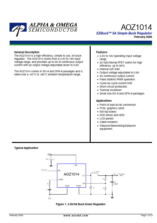
我司强势推出大电流电源IC\电源管理IC及大小功率的充电器IC,广泛应用在DVD, DVB(机顶盒),便携式DVD,车载DVD/VCD,液晶电视,液晶显示器,路由器,车载充电器,电瓶车控制电路板,车载冰箱,汽车音响,恒流串联LED灯驱动, VOIP,Audio,LCDM及各种小家电产品.XLSEMI产品应用领域1.DVB(机顶盒):XL1513,XL1580,XL1410(12V-1.8V/3.3V/5V/1A)2.Portable DVD:XL1410(12V-5V/3.3V/1.8V/1A),XL1580/XL1583(12 V-5V/1A)3.Video:XL1509-5.0S(12V-5V/1A)4.收音机电源:XL1509-ADJ,XL2576,XL2596组合DVD带音响/台式大收音机(带机芯):XL2576,XL2596,XL1509-ADJ5. LCD TV:XL1509-5.0/3.3、XL2596-5.0、6. LCDM:XL2596-5.0(12V-5V/3A),XL2596-3.3(15寸、17寸),XL15 07-5.0(12V-5V/1.5A)7. Audio:XL2596-5.0(12V-5V/3A)8. VOIP:XL1509-3.3(12V-3.3V/2A、12V-5V/1A),XL2596-3.39. 路由器:XL1509,XL1509-3.3,XL1410,XL151310. 液晶显示器:XL1501-3.3(12V-3.3V/3A)11.32寸以上液晶电视:XL4015(24V-12V/3A、24V-5V/5A)12.电梯控制板电源:XL2576,XL259613.锂电池包(多节锂电串联),移动电源,电池组,需恒压恒流充电:XL4001,XL4101,XL4015+358大功率锂电池包供电:XL6019,,XL6008,XL6007替代FP5138+MOS14.笔记本串联锂电池升压:XL6019,XL6008(12V~16V转19V/3A)15.车载MP3,MP4:XL1509,XL4001,XL1513(12V-5V/1 A)车载GPS:XL2596,XL150916.车载DVD:XL1507(12V-5V/1.5A,24V-5V/1.5A),XL1583(12V-5V/1.5A)17.公交车,出租车LED点阵显示屏:XL2576(24~36V转5V/1A)18.车载冰箱,汽车音响:XL4016(24V-12V/8A)19.车载充电器;XL1583,XL1410(12V~24V转5V/2A)XL4001,XL2001(12V~36V转5V/1.8A)XL4201,XL4101,XL2011,XL2012(12V~36V转5V/2.1A)XL4501,XL2013,(12V~36V转5V/3.1A~4.4A)XL1509(12V~36V转5V/1.5A),XL2576P(12V~36V转5V/1.5A),XL2576(12V~36V转5V/2A),XL2596(12V~36V转5V/2A),XL4013(12~24V转5V/3A),XL4015(12~24V转5V/4A),XL2001(12~24V转5V/1.8A),XL2011(12~24V转5V/2.1A),XL2012(12~24V转5V/2.4A),XL2013(12~24V转5V/3.2A),车充产品可以替代GL2576,GL2596,AX3007,AX3111,ACT4515,ACT4070,49 4+MOS,7500+MOS等方案20.上网本,笔记本车载充电器:60W以下的应用XL6009,XL6010,XL6011替代FP5138+MOS的方案,优点:线路简单,可靠性高升压方案(输入:10V~14V,输出:16V/19V,输出电流:2A,3A)升降压方案(输入:10V~30V,输出:12V/19V,输出电流:2A,3A)21.MR16射灯:XL30023*1W,4*1W ,5*1WLED模组驱动AC12V(DC10~16V)电子变压器升压供电:XL6003 5~7*1W,XL6005 10*1W车顶灯恒压输出,降压结构:XL1509车顶灯恒压输出,升压结构:XL6007,XL6008车顶灯恒压输出,升降压结构:XL6007,XL6008舞台灯XL2576,XL150922.电瓶车控制电路板:XL7001(60V转12V/5V/0.5A)23.安防产品:车载摄像头(小摄像头)供电:XL1509,XL1513小区,马路,建筑用的大摄像头,高速球供电:XL2596,XL1501摄像头里面用红外的LED灯驱动:XL1513,XL1530,XL1410市电和蓄电池混合供电:需要升降压应用XL6007,XL6008小区,大厦可视门铃对讲4寸,7寸屏供电:XL1509-ADJ,XL1410,XL1513,XL15 83(12V转5V/500mA)指示灯板:XL1513,XL141024.液晶电视数字屏,解码板电源驱动板:XL1513,XL153025.太阳能路灯,路标灯,庭院灯和5V~32V低压供电LED驱动,升降压应用领域:XL6003,XL6004,XL600526.大功率车载电源,降压,限流:XL4003+358,XL4005+358,XL4012+35827.降压型应用:XL4003,XL4005,XL4012可以替代PWM IC+MOS管等类似方案升压型应用:XL6007,XL6009,XL6010可以替代PWM IC+MOS管等类似方案升降压型应用:SEPIC BUCK-BOOST结构XL6007,XL6009,XL6010可以替代P WM IC+MOS管类似方案28.DVB:XL6007,XL6008马达天线供电(12V BOOST 19V/800mA)可以替代PWM IC+MOS管类似方案 CCD/CATVPMP/DSC/DSV/STB/VGA CardDPF(数码相框)PDALE D Panel背光LCD Panel背光移动电源应急充电器,可以替代FP5210+MOS,FP6210升压应用领域29.升压,恒压LED模组驱动:XL6007,XL6008,可以替代FP5210+MOS,FP621 0升压应用领域30.17寸以下LED背光驱动:XL6007,可以替代AMC3202的应用领域[1]XL14102APWM降压DC/DC,SOP8,输入3.6-18V,输出1.22V-16V转换效率高达90%,可替代BM1410A,TD1410,AP1512,AP1513,RM1410,GT1510,EC94 10,EC9410C,SD46520,ACT4060功能兼容AOZ1010AI,AOZ1015AI,EC9406[2]XL15833APWM降压DC/DC,SOP8,输入3.6-20V,输出1.23V-18V转换效率高达90%,可替代MP2355,ACT4060,MP1583,ZA3020,AOZ1014,MP1593[3]XL15132APWM降压DC/DC,SOP8,输入3.6-18V,输出0.8V-16V转换效率高达90%,可替代AP1513,OCP2020,BM1513/A,AX3101,RM2060,CX1513,EC9 413,AP1510,AP1520,AP1533,AP1534,AP5002功能兼容AOZ1010AI,AOZ1015AI,EC9406[4]XL15303APWM降压DC/DC,SOP8,输入3.6-18V,输出0.8V-16V转换效率高达90%,可替代AP1530,AP1538,AP1539,[5]XL25763APWM降压DC/DC,TO263/TO220,输入电压范围3.6-45V,可完全替换AE2576,BM2576,TD2576,AP1512/A,LM2576,LM2576,MIK2575,MIK2576A MC2576,OCP2006,HWD2575,EC942576[6]XL25963APWM降压DC/DC,TO263/TO220,输入电压范围3.6-45V,可完全替换AE2596,BM2596,TD2596,AP1501/A,AP1506,LM2596,AMC2596,MIK2596,OCP2011,OCP2016,GT1500,GT1504,AX2596,EC9401,CM2596S[7]XL15092APWM降压DC/DC,SOP8,输入3.6-36V,转换效率高达90%,功能替换LM2594,AE1509,TD1509,AP1509,OCP2019,HWD61410,EC9409,CM25 93.[8]XL4001,XL4101,XL4201,XL4501车载充电器,点烟器,恒流LED驱动,专用芯片150K2A/3A外部可调限流PWM降压DC/DC输入4.6V-40V可替代2576+431+324方案,34063+MOS+431+324方案[9]XL15073APWM降压DC/DC,TO252,输入3.6-36V,转换效率高达85%可完全替换AE1507,TD1507,AP1507,OCP2017,EC9407[10]XL4015大电流5APWM降压DC/DC,输入8-36V,输出0.8V-33V转换效率高达95%(功能兼容)---AOZ1014,LM2677,LM2678,LM2679[11]XL4012大电流12APWM降压DC/DC,TO220输入8-40V,输出0.8V-33V转换效率高达95%(功能兼容)---LM2677,LM2678,LM2679。
河海大学物联网工程学院本科毕业论文参考说明:⏹相关论文为团队整理的非官方的参考,仅作格式和内容写作参考,具体论文写作以学院和导师要求为准;⏹论文整理仅为方便各位同学交流学习之用,更多资源可以关注团队网站整理发布:孙浩毕业设计(论文)基于STM32和CPLD的可编程电机控制器的设计与研究专业年级 2007级自动化学号 20072167姓名孙浩指导教师张学武评阅人2011年6月中国常州河海大学本科毕业设计(论文)任务书(理工科类)1、毕业设计(论文)题目:基于STM32和CPLD的可编程电机控制器的设计与研究2、毕业设计目标:(1)培养综合运用知识、独立开展工程实践的能力;(2)结合课题任务得出合适的软硬件设计方案,训练分析与解决问题的能力(3)掌握C语言的编程与调试,训练运用C语言编程解决实际问题的能力(4)通过设计熟悉嵌入式系统在工业控制上的应用,掌握工业控制中的电气隔离、系统调试等方面的设计。
(5)通过独立完成毕业论文,熟悉查找外文文献的方法,掌握研究总结和论文的基本写作要领,培养独立撰写科技论文的能力。
3、研究方法及手段应用:(1)讨论确定研究的基本内容和相关技术,了解研究的背景。
(2)利用互联网和学校图书馆的资料,查找相关的知识,学习设计中需要研究的内容和相关知识。
(3)研究学习工业控制中的电气隔离、功率驱动等技术,学习处理器的相关外设,并能够熟练编程。
4、进度安排:2010.11-2010.12 选题,查阅相关书籍资料,确定好基本的设计方案,完成基本的原理图设计。
2011.1-2011.2研究学习相关的模块,完成第一版电路的硬件设计和制作,并进行部分外设的底层驱动开发。
2011.3-2011.5根据第一版电路的硬件设计和调试基础,设计第二版电路,完善电路设计,规范控制器的接口,完成最终的设计。
2010.6.1~2010.6.20 总结,撰写论文,准备答辩。
5、主要参考资料:[1] 王勇虹;徐炜STM32 系列ARM Cortex—M3 微控制器原理与实践2008 -北京: 北京航空航天大学出版社[2] JJ Labrosse 嵌入式实实时操作系统UCOS-II 2003 - 北京: 北京航空航天大学出版社[3] 杜尚峰CAN总线测控技术及其应用2006 北京:电子工业出版社指导教师:张学武时间:2010.12.7学生姓名:孙浩专业年级:07自动化摘要电动机是工业生产中不可缺少的一部分。

Valve configuration, see table ݘ:A =open in resting position C =closed in resting position Solenoid directional valves type DLOH, DLOKpoppet type leak free, direct operated, ISO 4401 size 06Table E041-17/EDLOH and DLOK are poppet type, two or three way, two position direct opera-ted solenoid valves, designed to operate in oil hydraulic systems with leak free requirements.They are operated by wet type solenoids type OE for DC and RC rectified current supply.The DLOH are available with optional manual prolonged override, protected by a rubber cap ܭ.Standard dimensions cartridge con-struction allows a wide variety of confi-gurations only by easy replacement of the cartridge ܫ.Cartridges of DLOH are available also as loose parts for mounting in manifolds,see They can be supplied with optional devi-ces for control of switching times.Standard electric connectors ܪable to satisfy the requirements of modern machines for electric interfaces charac-teristics.The coils ܩare fully encapsulated with temperature class H.Surface mounting: ISO 4401 size 06.Max flow:12 l/min (DLOH)30 l/min (DLOK).Max pressure:350 bar for DLOH315 bar for DLOK101MODEL CODEDLO2Directional control valve poppet type size 06H =max flow: 12 l/min K =max flow: 30 l/min2=two way (only DLOH)3=three way24DC **/*H -Series numberX = without connectorSee section ݚ for available connectors, to be ordered separatelyA /WP Options:/WP =prolonged manual override protected byrubber cap (only DLOH)/R =with check valve on port P, see ݘ (onlyDLOH)/S =no hand operation and poppet overlappingduring the intermediate position for safety applications (only DLOH)/L1, /L2, /L3=device for controlling switching time- O =solenoid OLK for DC supply (only for DLOK)- U =solenoid OLU for DC supply (only for DLOH)Voltage code, see section ݛ:00=solenoid valve without coilsU X -2VALVE CONFIGURATIONE041Seals material:omit for NBR(mineral oil & water glycol)PE = FPM666667669FunctionCode ofconnector4ELECTRIC/ELECTRONIC CONNECTORS ACCORDING TO DIN 43650The connectors must be ordered separatelyConnector IP-65, suitable for direct connection to electric supply sourceAs 666 connector IP-65 but with built-in signal led, suitable for direct connection to electric supply source With built-in rectifier bridge for supplying DC coils by alternating current (AC 110V and 230V - Imax 1A)3MAIN CHARACTERISTICS OF DIRECTIONAL VALVES TYPE DLOH, DLOKDLOHDLOKAssembly position / location Any positionSubplate surface finishing Roughness index Ra 0,4 - flatness ratio 0,01/100 (ISO 1101)Ambient temperature from -20°C to +70°CFluidHydraulic oil as per DIN 51524 .... 535; for other fluids see section ݗRecommended viscosity 15 ÷ 100 mm 2/s at 40°C (ISO VG 15 ÷ 100)Fluid contamination class ISO 4406 class 21/19/16 NAS 1638 class 10, in line filters of 25 μm (β25 _>75 recommended)Fluid temperature -20°C +60°C (standard seals and water glycol) -20°C +80°C (/PE seals)Flow direction As shown in the symbols of table ݘOperating pressurePorts P, A, B: 350 bar Port T: 160 barPorts P, A, B: 315 bar Port T: 210 barRated flow See diagrams Q/Δp at section ݜMaximum flow 12 l/min see operating limits at section ݝ30 l/min see operating limits at section ݝInternal leakageLess than 5 drops/min (≤ 0,36 cm 3/min) at max working pressureDLOH DLOK3.1 Coils characteristics Insulation classH (180°C) Due to the occuring surface temperatures of the solenoid coils, the European standards EN ISO 13732-1 and EN ISO 4413 must be taken into account Connector protection degree IP 65Relative duty factor100%Supply voltage and frequency See electric feature ݛSupply voltage tolerance ± 10%CertificationC UR USE041TEST CONDITIONS:- 8 l/min; 150 bar - nominal voltage- 2 bar of counter pressure on port T- based on mineral oil ISO VG 46 at 50°C The response time is affected by elasticity of the hydraulic circuit, by variation of hydraulic characteristics and temperatureDLO*-**–4525DLO*-**30–75DLO*-**/L1–6060DLO*-**/L2–8080DLO*-**/L3–110150666, 667669666, 667666, 667666, 667Switch-onACSwitch-onDCSwitch-offValve type Connector 8SWITCHING TIMES (average values in msec)(1)For other supply voltages availableon request see technical table E010.(2)Average values based on testsperformed at nominal hydraulic con-dition and ambient/coil temperature of 20°C.P →A A →T (P →B)(B →T)6FLOW VERSUS PRESSURE DROP DIAGRAM based on mineral oil ISO VG 46 at 50°CFlow rate [l/min]Flow rate [l/min]V a l v e p r e s s u r e d r o p Δp [b a r ]Flow rate [l/min]I n l e t p r e s s u r e [b a r ]V a l v e p r e s s u r e d r o p Δp [b a r ]7OPERATING LIMITS based on mineral oil ISO VG 46 at 50°CA =DLOH-3AB =DLOH-2A, DLOH-3CC =DLOK-3AD =DLOK-3CAD Flow rate [l/min]I n l e t p r e s s u r e [b a r ]C B E FDLOH-2A B –DLOH-2C C –DLOH-3A D C DLOH-3C C A DLOK-3A F E DLOK-3CFEFlow directionValve type(1)(1) For two-way valves, pressure drop refers to P →TThe diagram has been obtained with warm solenoids and power supply at lowest value (Vnom - 10%).AB CD5ELECTRIC FEATURESValveExternal supply nominal voltage ± 10%(1)Type ofconnectorPowerconsumption(2)Code of spare coil Colour of coil label DLOHDLOKDIRECT CURRENT6 DC12 DC 24 DC 48 DC110/50 AC 120/60 AC 230/50 AC 230/60 AC666or 66733 WCOU-6DC/ 80COUR-12DC /10COUR-24DC /10COU-48DC /80brown green red silver gold gold blue blue ––––––––110/50 AC 120/60 AC 230/50 AC 230/60 AC 669666or 66766940 VA 35 VA 40 VA 35 VA 32 W 40 W 40 VA 35 VA 40 VA 35 VACOU-110RC /80COUR-110RC /10COU-230RC /80COUR-230RC /10––––––––ALTERNATE CURRENTDIRECT CURRENTALTERNATE CURRENT12 DC 24 DC 110 DC 220 DC 6 DC 12 DC 24 DC 48 DC 110 RC220 RC110RC 230RC 230/60 AC 12 DC 24 DC 110 DC 220 DC Voltage code9DIMENSIONS [mm]10INSTALLATION DIMENSIONS OF CARTRIDGES [mm]。
AN ISO 9001 REGISTERED COMPANYon/off and modulatingFlow Control Division Worcester Actuation SystemsSeries 75 Electric Actuators from Worcester Actuation Systems add a new dimension of operational dependability and flexibility to modern processes controlled by computers, programmable controllers and other electric control equipment. A multi-function capability permits use of the Series 75 actuator throughout the process for on/off, throttling, variable-cycle and any analog or digital control. One of the most reliable electric actuators on the market, the Series 75 is lightweight, compact and powerful. Its split phase capacitor AC reversing motor or DC motor drives a valve through a sealed, permanently lubricated gear train which offers virtually lifetime maintenance-free dependable operation.The Series 75 is available in eight sizes and produces torques to 3000 in-lbs. Housings are designed to TYPE 1 General Purpose, TYPE 4Watertight, and TYPE 7, Class 1, Division 1 and 2, Group C, D and TYPE 9, Class II, Division 1 and 2, Group E, F, G. A combined location TYPE 4, 4X, 7, 9 enclosure is also available as a “Z” option. A baked polyester finish is the standard coating, but special coatings are avail-able for extreme hazardous-environment applications.Series 75 actuators may be used on Worcester Controls complete line of ball valves, other quarter-turn valves or devices requiring rotary operators. Moreover, their ability to provide power in both directions through selected arcs from 20°through 300°makes them ideal for control of heating, ventilating and air conditioning duct systems and automatic, remotely operated equipment.Worcester Controls Series 75A time-tested, high-quality state-of-the-art electric actuator for remote control of quarter-turn valves andother rotary devices. Simple, compact and reliable.2WCABR1014Flow Control DivisionWorcester Actuation Systems Options to Fit Your ApplicationsThe Series 75 can be ordered with a variety of options to tailor it tothe needs of your application.Cycle Length Control– This speed control feature allows field adjust-ment of opening and closing cycle times, 19 minutes for 25% dutyand 57 minutes for 75% duty actuators.Feedback (0-1000 ohm) Potentiometer– provides a variable resis-tance to signal the exact position of the output shaft and the valve itis powering.Position Indicator Board– provides a 4-20 mA valve position feedbacksignal to the control room.Heater/Thermostat – prevents condensation from collecting inside theactuator.Condensation Drain Plug– drains accumulated water.180°Center-Off Kit – provides an extra position for three-way valvesand is used for dribble-feed applications in quarter-turn valves.Additional Limit Switches– may be used to operate lights that indi-cate valve position or to operate other equipment.AF-17 Positioner Board– for control valves positions the actuatorbased on an input signal of current, voltage or resistance.DFP17 DataFlo P™– is a microprocessor-controlled electronic posi-tioner with software for on-site or remote operation and diagnostics.This new, smart positioner for Series 75 actuator driven controlvalves is controlled by a 4-20 mA analog signal from a PLC or digital-ly from a computer.DFC17 DataFlo C™– is a microprocessor based PID single-loop con-troller that accepts a variety of process inputs. All process parametersare easily programmed through the keypad or via a simple RS-485computer interface.I 75 Low-Current Circuit Interface– is a solid-state interface/relaybetween the PC/controller/computer and actuator motor(s). It pro-tects controlling device outputs from destructive feedback. Thishigh-voltage feedback is due to limit switch action, auto transformereffect of unused winding, and capacitor voltage. The unit, as a printedcircuit board, is conveniently mounted inside of standard enclosures.Maximum output ratings are 4 A for 120 VAC and 2 A for 240 VAC.Controllers with outputs that have low current ratings cannot be con-nected to electric actuator motor(s) that require a current greater thanthe controller rating.R 75 Remote Terminal Unit(RTU) – is an interface for DC powered actuators. This solid-state interface card allows you to control a DC-powered electric actuator by a control signal from the Remote Terminal or any low current system (such as a solar powered sys-tem). It is equipped with a field-adjustable current limiting circuit, which will trip the power in case of abnormal conditions (it will reset by reengaging the control signal). Optional contact closure to indicate the tripped condition; 0-5 VDC, 0-1000 ohm position feedback, and end of travel SPDT gold contact switches are available.DFP17 Positioner for ControlValvesTYPE 1Sizes 10, 12, 15, 20, 22(Enclosure Option – Blank)Combined TYPE 4, 7 & 9Sizes 25, 30(Enclosure – Z)Combined TYPE 4, 4X, 7 & 9Sizes 10, 12, 15, 20, 22, 23(Enclosure Option – Z)TYPE 4Sizes 10, 12, 15, 20, 22(Enclosure Option – W)TYPE 7 & 9Sizes 10, 12, 15, 20, 22(Enclosure Option – X)WCABR10143Sizes:Small: 10, 12, 15, 20, 22, 23 Large: 25, 30Torque:150-3000 in-lbs.Enclosures:TYPE 1 General Purpose TYPE 4 WatertightTYPE 7, Class I, Division 1, 2,Group C, DTYPE 9, Class II, Division 1, 2,Group E, F, G Hazardous LocationsTYPE 4, 4X, 7, & 9 CombinedLocations Enclosure Coatings: Corrosion resistant baked polyester finish standard. Consult Flowserve for special applications.Voltages:120 V and 240 VAC, 12 V and 24 VDCConnection:Male output shaft (female shaft available on request)Gearing:Small: Sealed, permanently lubri-cated spur gear module driving a final dual-torque bull gearLarge: Two-stage planetary gear,permanently lubricated self-lock-ing gear trainOverload Protection:AC only. Thermal overload pro-tector with automatic reset.Travel Stop Limit Switches: Two SPDT, all sizes; internal,independent, adjustable.Actuated by cams mounted on drive shaft. Adjustable from 20°to 300°.Manual Override:All sizes, TYPE 4, 7 and 9 only. Lift position indicator and turnshaft: Sizes 10,12,15, 20,22, 23.Turn side-mounted handwheel:Sizes 25 and 30.rotation.4WCABR1014Flow Control DivisionWorcester Actuation SystemsSpecificationsWCABR10145Flow Control DivisionWorcester Actuation SystemsDimensions inches (mm)Sizes 10, 12, 15, 20, 22TYPE 1 (General Purpose)Sizes 10, 12,15, 20, 22, 23TYPE 4 (Watertight) Enclosure - W,TYPE 7 & 9 (Hazardous Locations) Enclosure - X, TYPE 4, 7 & 9 (Combined) Enclosure - Z (shown)Sizes 25, 30TYPE 4 (Watertight) andTYPE 7 & 9 (Hazardous Locations) Combined Enclosure - Z(4 HOLES)1/4" - 20 UNC TAP x .38 (9.7) DEEP(4 HOLES)3/4 "NPT 1 Optional 1/2 " NPT 1/2" NPT Cover Removal Allowance: 6.27 inches min.( 4 HOLES)MOUNTING PATTERN1/4" - 20 UNC TAP x .38 (9.7) DEEP1/2"Main A Type 1, Sizes 10, 12, 15, 20, 22All other types and sizes6WCABR1014Flow Control DivisionWorcester Actuation SystemsWiring DiagramsSizes 10-30 AC PowerIMPORTANT!EACH ACTUATOR SHOULD BE ELECTRICAL-LY POWERED THROUGH ITS OWNINDIVIDUAL SINGLE-POLE SWITCH CON-TACTS TO ISOLATE THE UNUSED WINDING.NOTE: ACTUATOR SHOWN IN COUNTER-CLOCKWISE EXTREME OF TRAVEL, OR "OPEN" POSITION.Sizes 10-23 DC PowerNOTE: AC and DC wiring diagrams shown are for W, X and Z enclosures only. DCwiring diagram shown is for size 10, 20 and 23 actuators. For size 12 and 22 actuators,the red/black motor leads are reversed.Design OptionsA mechanical brake is used for all butterfly valve applications or when the actuator must be stopped instantaneously and securely. (Used on 10-23 sizes only.)Available for AC actuators only.Prevents destructive pipeline shock caused by fast opening or closing valves on steam or hydraulic service. The CLC units allow field adjustment of the standard actuator’s cycle time up to approximately 19 minutes for 25%duty and 57 minutes for 75% duty actuators.Additional Options Available. Consult Flowserve.NOTE:A 2" CPT valve should not be sized with an electric actuator smaller than 2275, and a mechanical brake must be ordered.May be mounted to either operate lights,indicate valve position, or operate other equipment such as pumps, compres-sors, mixers, etc.Heater/Thermostat180°Center-off (three positions)Mechanical BrakeA feedbackpotentiometer is used when remote indication is desired.Potentiometers are available in 1000 ohms.A heater/thermostat kit for cold ambient temperatures or humid environments uses a 15-watt heater and a ther-mostat set to close at temperatures below 70°F ambient.Used with three-way valves or similar products requiring a mid-position stop capability for shutoff. May be adjusted for travel other than 180°.NOTE: A three-posi-tion switch is required for operation.Feedback PotentiometerCycle Length Control (CLC)Limit SwitchesOne Limit Switch Two Limit SwitchesWCABR10147Sizes 25, 30Sizes 25, 30Sizes 10-23Item Qty.DescriptionMaterial11Base Aluminum Casting 21Cover Aluminum Casting 31Base Plate Zinc Casting 41Motor Module Zinc Casting 51Output Shaft Steel 62Gear Drive Pin Steel 71Bull GearSteel81Capacitor (w/Fiber Phenolic Encapsulated Washer if Required)91Capacitor Bracket Steel101Terminal Strip Polyethylene Based Material 112Limit SwitchPhenolic Encapsulated 122Limit Switch Cam Zinc Casting 131/Cam Cam Set Screw Steel 144Limit Switch Screw Steel 156Base Plate Screw Steel168Hex Screw (W,X,Z)Stainless SteelItem Qty.DescriptionMaterial164Hex Screw (GP)Steel171Position Indicator (W,X,Z)Molded Phenolic 181Indicator Set Screw (W,X,Z)Steel191Seal (W,X,Z)Reinforced Rubber 201Gasket (W only)Neoprene 201Flange Seal (Z only)Buna N 211Bearing Bronze221Seal Reinforced Nitrile 234ScrewSteel 244Lock Washer Steel251Conduit Plug Polyethylene 261Capacitor Tie Plastic 271Bearing (W, X, Z)Bronze 281Roller Bearing (size 23 only)Steel 291Bearing, Base Plate Nylon 301O-Ring (W, X, Z)Buna 312Insulator (not shown)NylonItem Qty.DescriptionMaterial11Base Aluminum 21CoverAluminum 31Gear Train Support Aluminum 41Motor51Output Gear Steel Casting 62Planet Gear Hardened Steel 71Planetary Gear Ductile Iron 81Worm Gear Steel 91Sensing Shaft Steel 102Pin, Spring Steel112Shaft Hardened Steel 122BushingBronze 132Thrust Washer Steel 141Pin, SpringSteel 154Belleville Washer Steel 161Nut Steel172SealRubber, Steel 181Manual Override Shaft Steel 191Pin, Cotter Steel 201Pin, SpringSteel211Handwheel, Manual Override Aluminum 221Thrust Washer Steel 231Tru-arc Ring Steel241Seal Rubber, Steel 251Sun Gear Steel 261Bushing Bronze 274Cap ScrewSteelItem Qty.DescriptionMaterial284Lock WasherSteel291Capacitor (w/Fiber Washer Phenolic Encapsulated if Required)301Input Gear Steel 311NutSteel 321Cap ScrewSteel331Position Indicator Aluminum 341BushingBronze 351Motor Support Plate Aluminum 361Gear, Pinion Steel 372Set Screw Steel381Terminal Strip Polyethylene Based Material 392Limit Switch Cam Zinc Casting 401/Cam Cam Set Screw Steel 411FanPlastic422Limit Switches Phenolic Encapsulated 431O-Ring Buna 449Cap Screw Steel 459Lock Washer Steel 4612Cap ScrewSteel 471Sensing Shaft Ret. Ring Steel481Conduit Plug Polyethylene 491Capacitor Bracket Steel 501Capacitor TiePlastic 511Capacitor Bracket ScrewSteelSizes 10-23How to Order*1575 can only be ordered with a 20% duty 120 VAC motor. The 2375 can only be ordered with a 75% duty motor.†† Specify operation in Option Operation column for CLC.† 120 and 240 VAC actuators will operate on 50 Hz. Torque will remain the same, cycle time will increase by a factor of 1.2 and duty cycle will be reduced by a factor of approximately 20%. **These options must be ordered as a separate item in addition to being specified in the actuator code.***Can only be ordered with a 75% duty motor.NOTE: TYPE 7, 9, (X) UL approved units are available on request. TYPE 4, 7, 9, (X, W, Z) are furnished CSA Approved.Due to continuous development of our product range, we reserve the right to alter the product specifications contained in this brochure as required.Flowserve Corporation has established industry leadership in the design and manufacture of its products. When properly selected, this Flowserve product is designed to perform its intended function safely during its useful life. However, the purchaser or user of Flowserve products should be aware that Flowserve products might be used in numerous applications under a wide variety of industrial service conditions. Although Flowserve can (and often does) provide general guidelines, it cannot provide specific data and warnings for all possible applications. The purchaser/user must therefore assume the ultimate responsibility for the proper sizing and selection, installation, operation, and maintenance of Flowserve products. The purchaser/user should read and understand the Installation Operation Maintenance (IOM) instructions included with the product, and train its employees and contractors in the safe use of Flowserve products in connection with the specific application.While the information and specifications contained in this literature are believed to be accurate, they are supplied for informative purposes only and should not be considered certified or as a guarantee of satisfactory results by reliance thereon. Nothing contained herein is to be construed as a warranty or guarantee, express or implied, regarding any matter with respect to this product. Because Flowserve is continually improving and upgrading its product design, the specifications, dimensions and information contained herein are subject to change without notice. Should any question arise concerning these provisions, the purchaser/user should contact Flowserve Corporation at any one of its worldwide operations or offices.For more information about Flowserve Corporation, contact or call USA 1-800-225-6989.FLOWSERVE CORPORATIONFLOW CONTROL DIVISIONWorcester Actuation Systems5114 Woodall RoadP.O. Box 11318Lynchburg, VA 24506-1318Phone: 434 528 4400Facsimile: 434 845 9736Printed in USA 11/03© 2003 Flowserve Corporation, Irving, Texas, USA. Flowserve and Worcester Controls are registered trademarks of Flowserve Corporation.WCABR1014 (Part PB 730)。
Products Solutions Services KA01092F/00/ZH/14.1271216748简明操作指南Gammapilot M FMG60放射线测量仪表本文档为《简明操作指南》;不得替代随箱包装中的《操作手册》。
详细信息请参考随箱CD光盘中的《操作手册》和其他文档资料,或登录以下网址查询:/deviceviewer。
目录Gammapilot M FMG60 HART 2Endress+Hauser目录1 安全指南. . . . . . . . . . . . . . . . . . . . . . . . . . . . . . . . . . . . . . . . . . . . . . . . . . . . . . . . . . . . . . . . . 31.1 指定用途 . . . . . . . . . . . . . . . . . . . . . . . . . . . . . . . . . . . . . . . . . . . . . . . . . . . . . . . . . . . . . . . . . . . . . . . . . . . . . . . . . . . . . . . . . 31.2 安装、调试和操作 . . . . . . . . . . . . . . . . . . . . . . . . . . . . . . . . . . . . . . . . . . . . . . . . . . . . . . . . . . . . . . . . . . . . . . . . . . . . . . . . . 31.3 操作安全和过程安全 . . . . . . . . . . . . . . . . . . . . . . . . . . . . . . . . . . . . . . . . . . . . . . . . . . . . . . . . . . . . . . . . . . . . . . . . . . . . . . . 31.4 危险区域 . . . . . . . . . . . . . . . . . . . . . . . . . . . . . . . . . . . . . . . . . . . . . . . . . . . . . . . . . . . . . . . . . . . . . . . . . . . . . . . . . . . . . . . . . 41.5 辐射防护 . . . . . . . . . . . . . . . . . . . . . . . . . . . . . . . . . . . . . . . . . . . . . . . . . . . . . . . . . . . . . . . . . . . . . . . . . . . . . . . . . . . . . . . . . 51.6 图标 . . . . . . . . . . . . . . . . . . . . . . . . . . . . . . . . . . . . . . . . . . . . . . . . . . . . . . . . . . . . . . . . . . . . . . . . . . . . . . . . . . . . . . . . . . . . . 62 安装. . . . . . . . . . . . . . . . . . . . . . . . . . . . . . . . . . . . . . . . . . . . . . . . . . . . . . . . . . . . . . . . . . . . . 82.1 到货验收、运输、储存 . . . . . . . . . . . . . . . . . . . . . . . . . . . . . . . . . . . . . . . . . . . . . . . . . . . . . . . . . . . . . . . . . . . . . . . . . . . . . 82.2 安装条件 . . . . . . . . . . . . . . . . . . . . . . . . . . . . . . . . . . . . . . . . . . . . . . . . . . . . . . . . . . . . . . . . . . . . . . . . . . . . . . . . . . . . . . . . . 82.3 水冷 . . . . . . . . . . . . . . . . . . . . . . . . . . . . . . . . . . . . . . . . . . . . . . . . . . . . . . . . . . . . . . . . . . . . . . . . . . . . . . . . . . . . . . . . . . . . 122.4 安装后检查 . . . . . . . . . . . . . . . . . . . . . . . . . . . . . . . . . . . . . . . . . . . . . . . . . . . . . . . . . . . . . . . . . . . . . . . . . . . . . . . . . . . . . . 123 接线 . . . . . . . . . . . . . . . . . . . . . . . . . . . . . . . . . . . . . . . . . . . . . . . . . . . . . . . . . . . . . . . . . . . 133.1 电缆入口 . . . . . . . . . . . . . . . . . . . . . . . . . . . . . . . . . . . . . . . . . . . . . . . . . . . . . . . . . . . . . . . . . . . . . . . . . . . . . . . . . . . . . . . . 143.2 接线端子分配 . . . . . . . . . . . . . . . . . . . . . . . . . . . . . . . . . . . . . . . . . . . . . . . . . . . . . . . . . . . . . . . . . . . . . . . . . . . . . . . . . . . . 153.3 电势平衡 . . . . . . . . . . . . . . . . . . . . . . . . . . . . . . . . . . . . . . . . . . . . . . . . . . . . . . . . . . . . . . . . . . . . . . . . . . . . . . . . . . . . . . . . 163.4 在端子接线腔1中接线 . . . . . . . . . . . . . . . . . . . . . . . . . . . . . . . . . . . . . . . . . . . . . . . . . . . . . . . . . . . . . . . . . . . . . . . . . . . . 173.5 在端子接线腔2中接线 . . . . . . . . . . . . . . . . . . . . . . . . . . . . . . . . . . . . . . . . . . . . . . . . . . . . . . . . . . . . . . . . . . . . . . . . . . . . 183.6 连接分离型显示与操作单元FHX40 . . . . . . . . . . . . . . . . . . . . . . . . . . . . . . . . . . . . . . . . . . . . . . . . . . . . . . . . . . . . . . . . . 193.7 在级联连接方式中接线 . . . . . . . . . . . . . . . . . . . . . . . . . . . . . . . . . . . . . . . . . . . . . . . . . . . . . . . . . . . . . . . . . . . . . . . . . . . . 193.8 限位检测(200/400 mm)的连接实例 . . . . . . . . . . . . . . . . . . . . . . . . . . . . . . . . . . . . . . . . . . . . . . . . . . . . . . . . . . . . . . . 203.9 连接后检查 . . . . . . . . . . . . . . . . . . . . . . . . . . . . . . . . . . . . . . . . . . . . . . . . . . . . . . . . . . . . . . . . . . . . . . . . . . . . . . . . . . . . . . 214 操作 . . . . . . . . . . . . . . . . . . . . . . . . . . . . . . . . . . . . . . . . . . . . . . . . . . . . . . . . . . . . . . . . . . . 224.1 操作菜单结构 . . . . . . . . . . . . . . . . . . . . . . . . . . . . . . . . . . . . . . . . . . . . . . . . . . . . . . . . . . . . . . . . . . . . . . . . . . . . . . . . . . . . 224.2 显示与操作单元 . . . . . . . . . . . . . . . . . . . . . . . . . . . . . . . . . . . . . . . . . . . . . . . . . . . . . . . . . . . . . . . . . . . . . . . . . . . . . . . . . . 235 调试 . . . . . . . . . . . . . . . . . . . . . . . . . . . . . . . . . . . . . . . . . . . . . . . . . . . . . . . . . . . . . . . . . . . 255.1 标定:概述 . . . . . . . . . . . . . . . . . . . . . . . . . . . . . . . . . . . . . . . . . . . . . . . . . . . . . . . . . . . . . . . . . . . . . . . . . . . . . . . . . . . . . . 255.2 功能检查 . . . . . . . . . . . . . . . . . . . . . . . . . . . . . . . . . . . . . . . . . . . . . . . . . . . . . . . . . . . . . . . . . . . . . . . . . . . . . . . . . . . . . . . . 255.3 开启测量设备 . . . . . . . . . . . . . . . . . . . . . . . . . . . . . . . . . . . . . . . . . . . . . . . . . . . . . . . . . . . . . . . . . . . . . . . . . . . . . . . . . . . . 265.4 基本设置 . . . . . . . . . . . . . . . . . . . . . . . . . . . . . . . . . . . . . . . . . . . . . . . . . . . . . . . . . . . . . . . . . . . . . . . . . . . . . . . . . . . . . . . . 275.5 物位测量和限位检测的标定 . . . . . . . . . . . . . . . . . . . . . . . . . . . . . . . . . . . . . . . . . . . . . . . . . . . . . . . . . . . . . . . . . . . . . . . . 345.6 密度和浓度测量的标定 . . . . . . . . . . . . . . . . . . . . . . . . . . . . . . . . . . . . . . . . . . . . . . . . . . . . . . . . . . . . . . . . . . . . . . . . . . . . 465.7 密度测量/温度补偿 . . . . . . . . . . . . . . . . . . . . . . . . . . . . . . . . . . . . . . . . . . . . . . . . . . . . . . . . . . . . . . . . . . . . . . . . . . . . . . 585.8 放射线成像检测 . . . . . . . . . . . . . . . . . . . . . . . . . . . . . . . . . . . . . . . . . . . . . . . . . . . . . . . . . . . . . . . . . . . . . . . . . . . . . . . . . . 585.9 SIL 锁定(限位检测,200/400 mm,PVT 闪烁体) . . . . . . . . . . . . . . . . . . . . . . . . . . . . . . . . . . . . . . . . . . . . . . . . . . . . 58Gammapilot M FMG60 HART 安全指南Endress+Hauser 31安全指南1.1指定用途Gammapilot M 是一体式变送器,用于非接触式物位、限位、密度和浓度测量。